CTP2000 Series Console Cable Pinouts
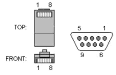
The console port CTP2008, CTP2024, and CTP2056 devices with the new PP833 processor uses a USB-type connector located on the right of the PP833 faceplate labelled “RS-232”. CTP2000 series devices with the PP310 and PP332 processors use an RJ-45 connected to the COM2 port. This cable must be connected during the first boot process. Use a shielded cable for the COM2 port on the CTP2056 device. Figure 1 displays the console cable pin configurations for CTP2000 series devices with the PP310 and PP332 processors. On the left is the RJ-45 connector, and on the right is the DB-9 connector with the pin numbering indicated.
The console connections are configured to the following parameters:
-
Speed: 9600 bps
-
Data bits: 8
-
Stop bits: 1
-
Flow control: Xon/Xoff
-
Parity: none

Table 1 and Table 2 list console cable pinouts for CTP2000 Series devices based on the pin configurations.
| CTP RJ-45 Pin | Console DB-9 Pin |
|---|---|
|
1 RTS |
8 CTS |
|
2 DTR |
6 DSR |
|
3 TXD |
5 GND |
|
4 GND |
2 RXD |
|
5 GND |
3 TXD |
|
6 (tied to pin 7) RXD |
1 DCD |
|
7 DSR |
4 DTR |
|
8 CTS |
7 RTS |
| USB Console Connector | DB-9 plug |
|---|---|
|
2 RXD |
3 TXD |
|
3 TXD |
2 RXD |
|
4 GND |
5 GND |
| RJ-45 | DB-9 |
|---|---|
|
3 (GND) |
5 GND |
|
4 (TXD) |
3 TXD |
|
5 (RXD) |
2 RXD |
| RJ-45 | DB-9 |
|---|---|
|
1 RTS |
7 RTS |
|
2 DTR |
4 DTR |
|
3 TXD |
3 TXD |
|
4 GND |
5 GND |
|
6 RXD |
2 RXD |
|
7 DSR |
6 DSR |
|
8 CTS |
8 CTS |
| RJ-45 | DB-9 |
|---|---|
|
1 RTS |
8 CTS |
|
2 DTR |
6 DSR |
|
3 TXD |
2 RXD |
|
4 GND |
5 GND |
|
6 RXD |
3 TXD |
|
7 DSR |
4 DTR |
|
8 CTS |
7 RTS |
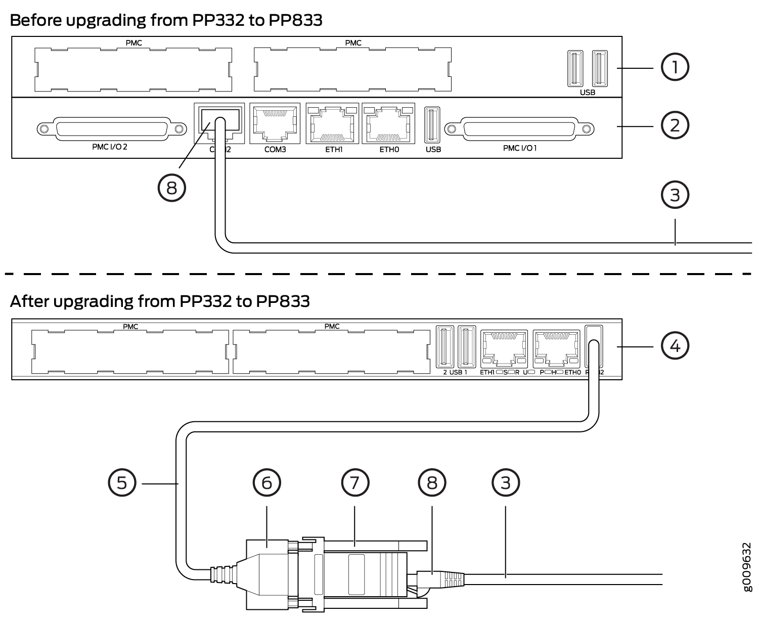
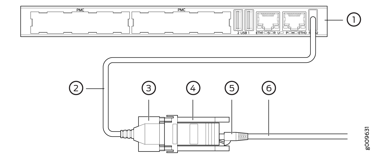
You can connect a console (PC, Macintosh, or UNIX workstation) directly to the COM2 port on the PP310 and PP332 processors. On the PP833 processor, a console is connected using the supplied USB-to-DB9 cable (p/n 720-071594), in which the DB-9 connector has the same pinout as a standard RS-232 DTE port. When the USB-to-DB9 cable is used in conjunction with the DB-9 adapter labelled “p/n 450-071855” (see Figure 2), the available RJ-45 console pinout will be the same as the console connection on the RTM of PP332/PP310 processor.
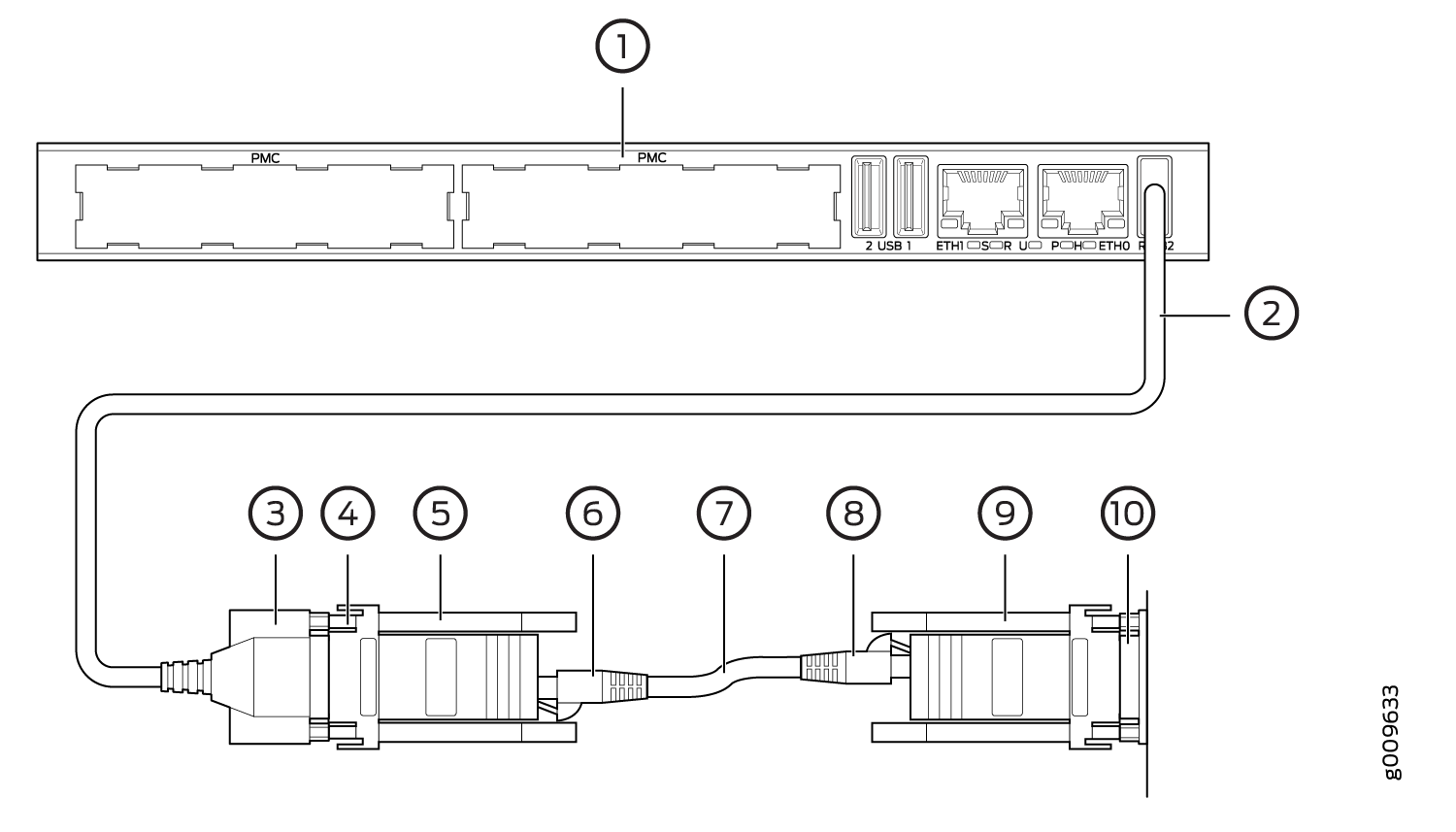
Alternatively, if the DB-9 adapter from the bag labelled “p/n 720-056657” (see Figure 3) is used instead of “p/n 450-071855”, the available RJ-45 console pinout will be similar to the CTP150 console port (and other Juniper routers). To connect the PP833 processor with the DB-9 plug serial port of a PC, additionally connect a straight RJ-45 cable with the DB-9 adapter from the bag labelled “p/n 720-056657”. The other end of the RJ-45 cable connects to the DB-9 adapter from the bag labelled “p/n 720-014126” (see Figure 4). Then, you can connect the PC’s DB-9 plug connector with the DB-9 adapter “p/n 720-014126”.

1 — PP332 front panel | 5 — Cable 720-071594 |
2 — PP332 RTM panel | 6 — DB-9 plug end of 720-071594 |
3 — User’s existing console cable | 7 — Adapter 450-071855 |
4 — PP833 front panel | 8 — RJ-45 plug end of user’s existing console cable |

1 — PP833 front panel | 4 — Adapter from the bag labelled 720-056657 |
2 — Cable 720-071594 | 5 — RJ-45 plug end of user’s console cable |
3 — DB-9 plug end of 720-071594 | 6 — User’s cable that connects to the console on a CTP150 or other Juniper product |

1 — PP833 front panel | 6 — RJ-45 plug end |
2 — Cable 720-071594 | 7 — Straight RJ-45 cable |
3 — DB-9 plug end of 720-071594 | 8 — RJ-45 plug end |
4 — DB-9 socket end of adapter from the bag labelled 720-056657 | 9 — Adapter from the bag labelled 720-014126 |
5 — Adapter from the bag labelled 720-056657 | 10 — DB-9 plug end of PC |
Upgrading from PP833 to PPF84 Processor
To upgrade from PP833 to PPF84:
Replace the PMC card in the PP8333 processor with XMC card. For more information on installing XMC card, see Installing and Removing XMC Module.
-
You don't need an adapter for PPF84, as it has RJ45 console port. See Figure 1.
-
Make sure to have CTP2000-IM-2WFXS-B with 2 PSUs when upgrading to PPF84.
