Installing and Removing XMC Module
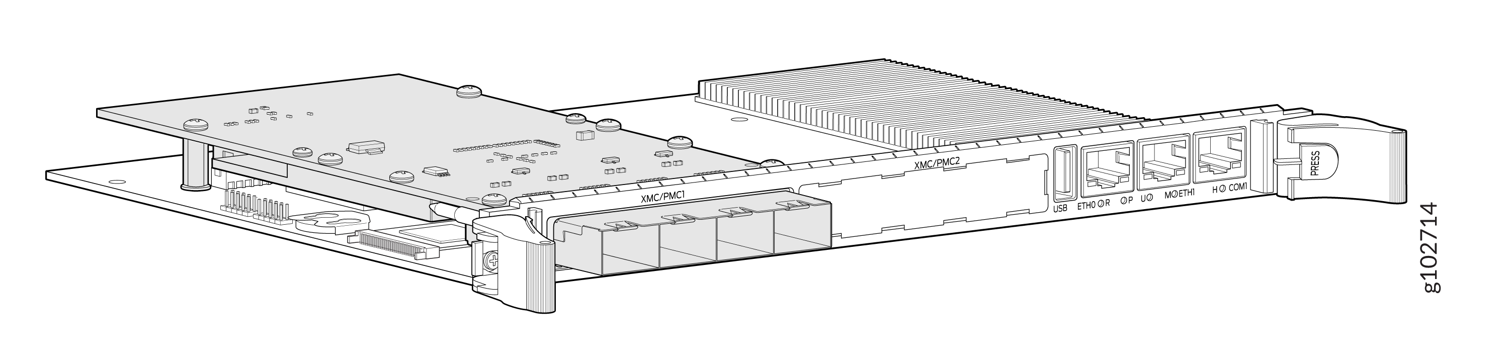
The Quad-port Gigabit Ethernet Extended mezzanine card (XMC) is mounted on the CTP2000-PRC-04-S processor board and can be installed or replaced in the field. The XMC mounting hardware is provided in a ziplock bag for assembly. The processor’s front panel supports two compatible XMC modules.
To install the XMC on the CTP2000-PRC-04-S processor board:
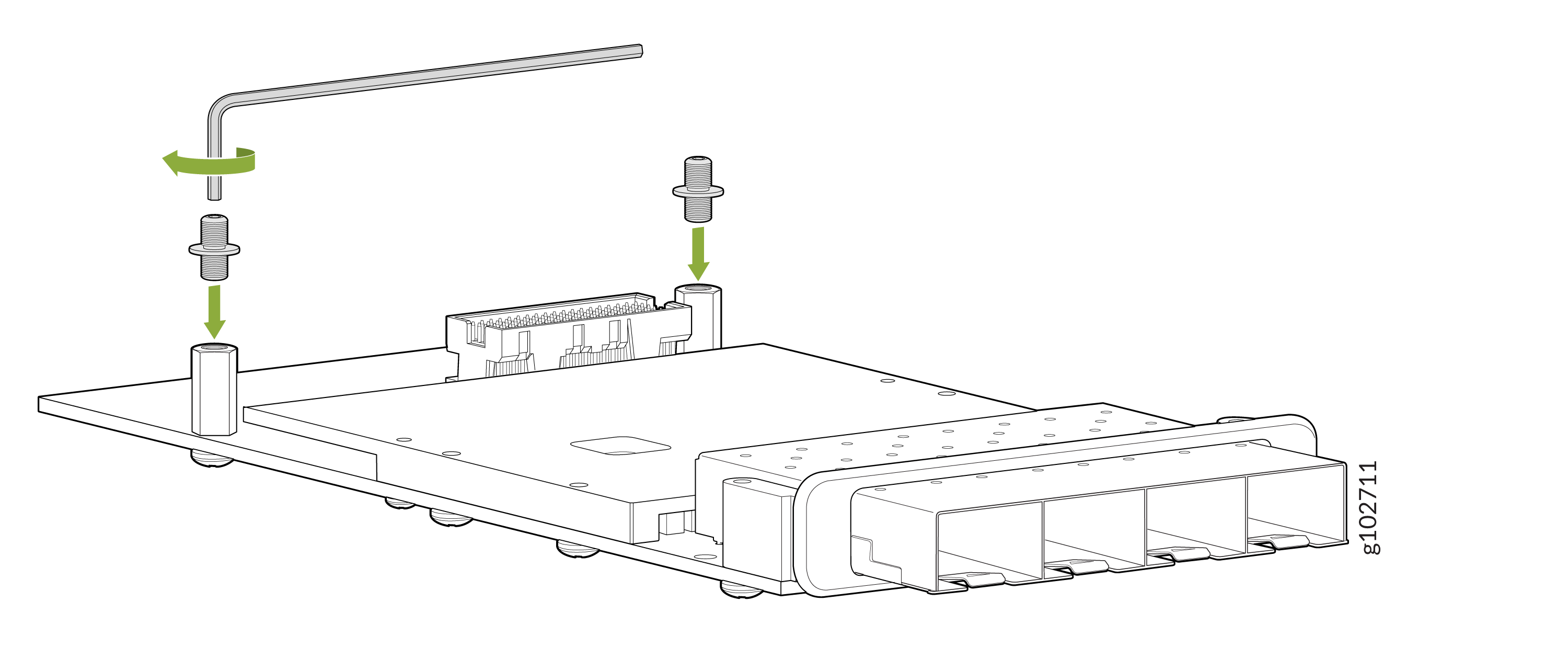
Screw the male-male jackscrew bases into the JSOM standoffs already installed on the XMC module, using a 1.5mm hex/Allen wrench (not provided).
Install the XMC mezzanine onto the processor board. Ensure that the module is properly aligned with the processor board, such that the jackscrews are inserted into the carrier board mounting holes and protrude out the rear of the processor board.
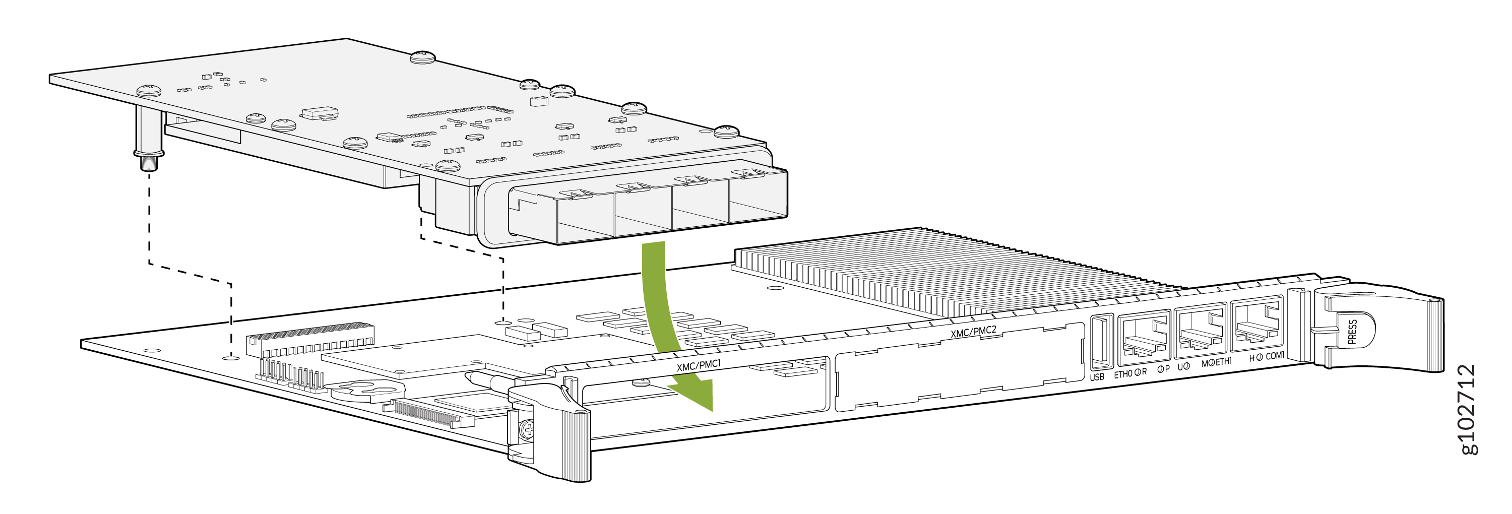
On the mounting points provided near the front panel, assemble the XMC mezzanine card with the two black colored Phillips head screws provided. Assembly torque of 3.2lbs-in is recommended.
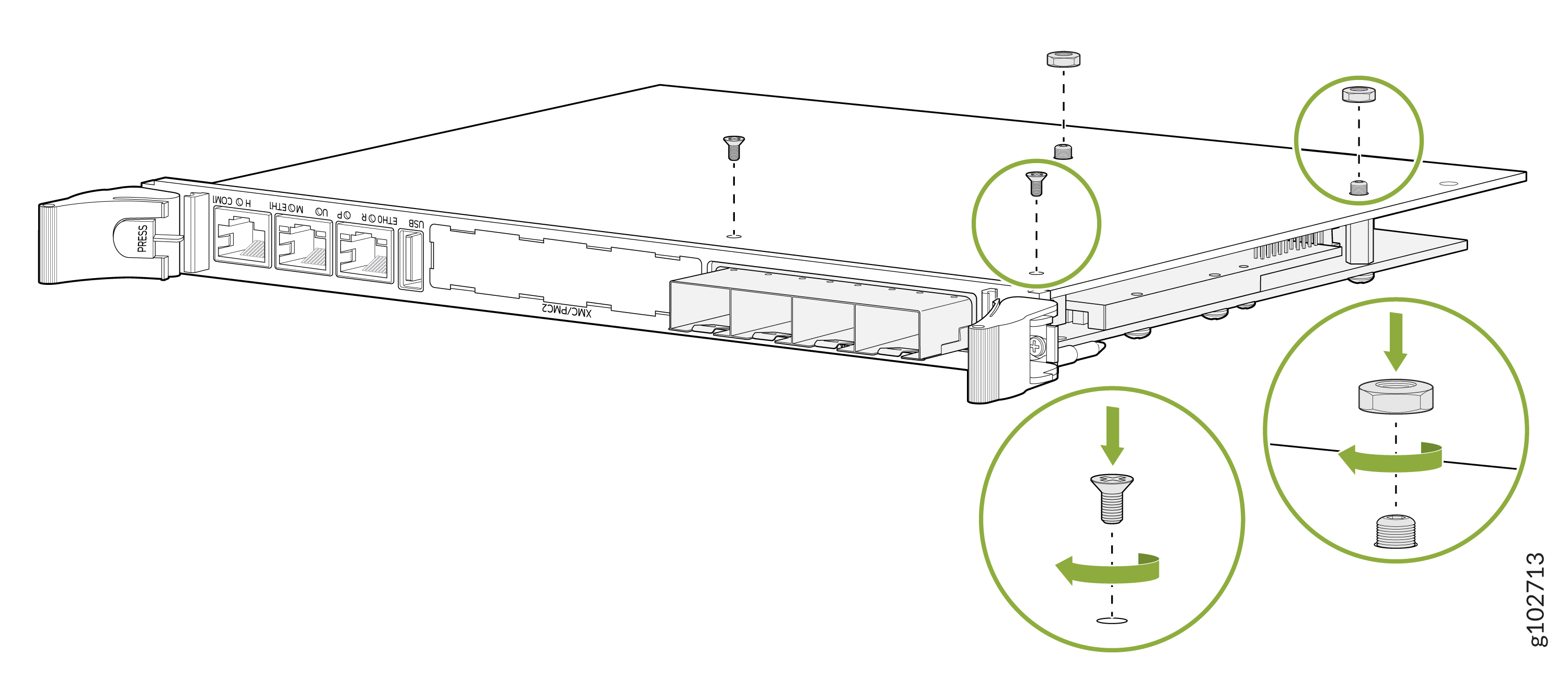
Install the provided hex nuts onto the protruding jackscrews on the rear side of the processor board to complete the installation.
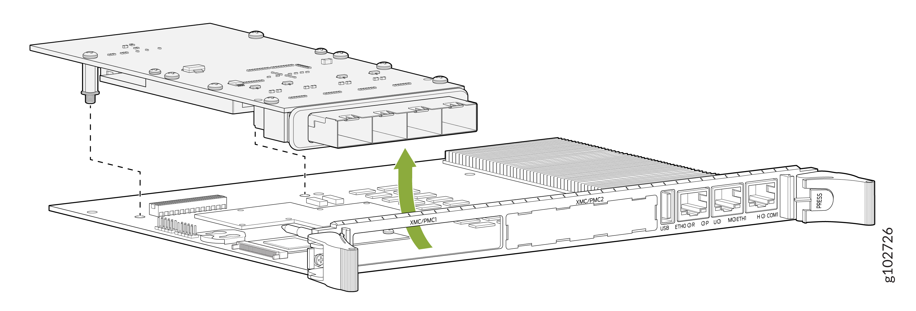
To remove the XMC from the CTP2000-PRC-04-S processor board:
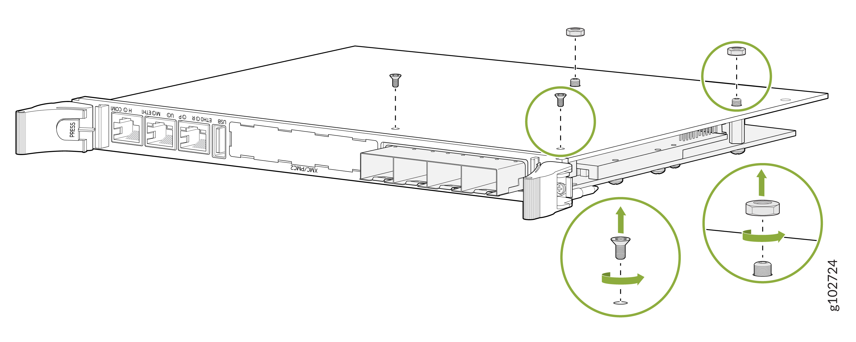
Remove the hex nuts from jackscrews on the rear side of processor board.
Unscrew the two black Phillips head mounting screws near the front panel.
Insert hex/Allen wrench into the hex opening of one of the jackscrews and turn counter-clockwise, for a quarter turn.
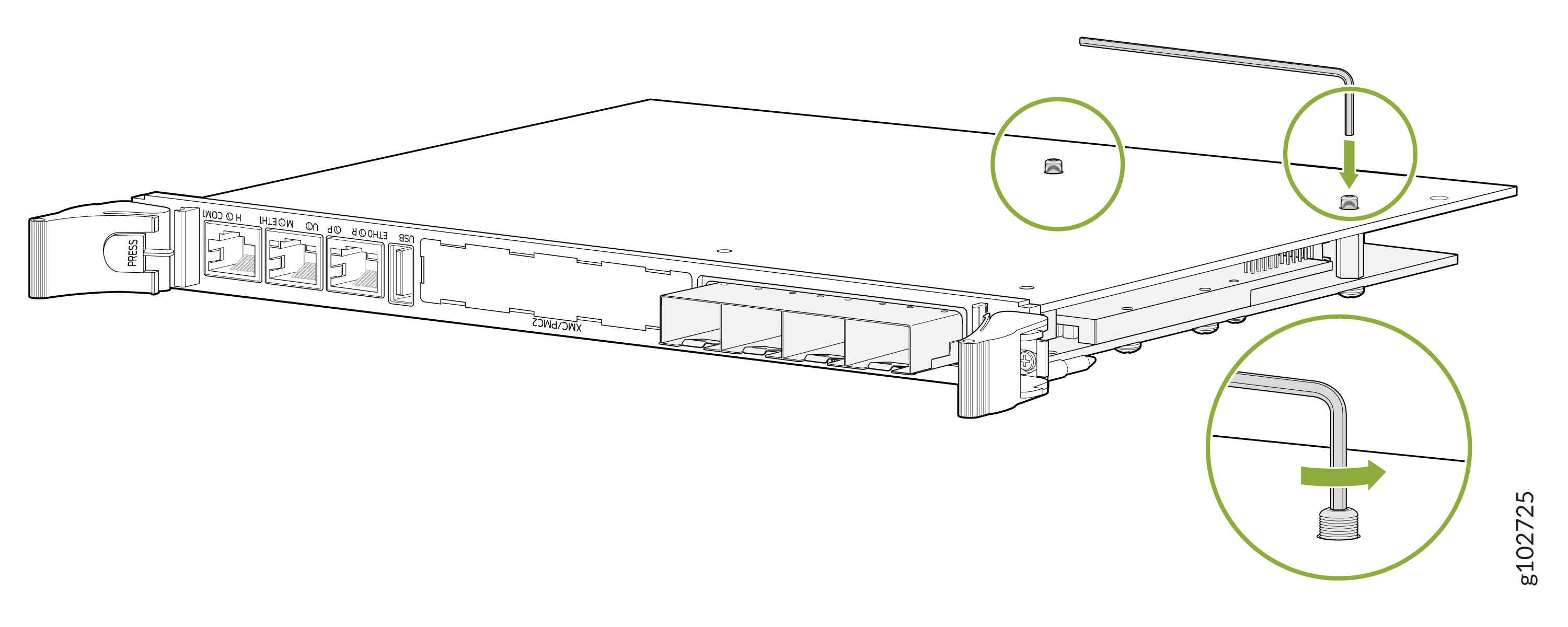
Similarly, using the hex/Allen wrench unscrew the other hex nuts to about a quarter turn, counter-clockwise.
Alternate back and forth between each standoff, a quarter turn at a time, until the connectors unmate and the jackscrews are fully unscrewed from the standoff bases.