CTP2000 Series Processor
We have announced End of Life (EOL) for certain CTP platforms (1004, 1012), CTP processors (PP310 and PP332), and components (CTP2000-8P-IRIG module and CTP2000 Compression module). However, we have retained the documentation for these components to facilitate the existing users who continue to use the older platforms or components. If you are using an older processor, we recommend that you upgrade your CTP2000 processor to the new processor, PPF84, for a smoother experience and support. To know more about EoL of CTP products, see https://support.juniper.net/support/eol/product/ctp_series/.
Starting in CTPOS Release 9.1R6, Juniper Networks CTP2000 Series Circuit to Packet platforms support the PPF84 processor (see Figure 1) in addition to the older PP833 processor.
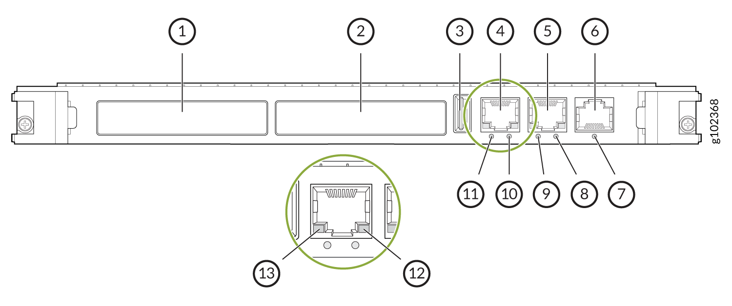
The front panel of the PPF84 processor comprises the following components:
1 — XMC1—Both XMC slots are available to support compatible fiber XMC modules. For more information about the XMC module, see CTP2000 XMC Module and Installing and Removing XMC Module. | 7 — LED indicating the status of the COM 1 port. This LED is used when the board is hot-swapped, and lights blue to indicate when the board can be safely removed from the chassis. |
2 — XMC2 | 8 — LED indicating the status of the Ethernet-2 port speed. This LED lights yellow when there is activity on the M.2 interface if supported by the M.2 module fitted. This LED is driven by a signal from the M.2 module but not all M.2 modules drive the signal. |
3 — USB 2.0 | 9 — LED indicating the status of the Ethernet-2 port link/activity. This LED flashes red rapidly when the CPU reaches it maximum specified operating temperature |
4 — Ethernet port 1—Provides the 1-Gbps Ethernet connection to the IP network by means of a local Ethernet switch or router. | 10 — LED indicating the status of the Ethernet-1 port speed. This POST LED is used to indicate that a power on self-test has failed. This LED will also flash when outputting sound on the speaker. The LED will be OFF when the board is in reset, power cycling or powered down/in sleep state. |
5 — Ethernet port 2 | 11 — LED indicating the status of the Ethernet-1 port link/activity. This Run LED lights green to indicate and assess processor activity. |
6 — COM 1—(RJ45) Provides an asynchronous tty connection for locally configuring the CTP Series device. |
The PPF84 processor does not support PMC card.
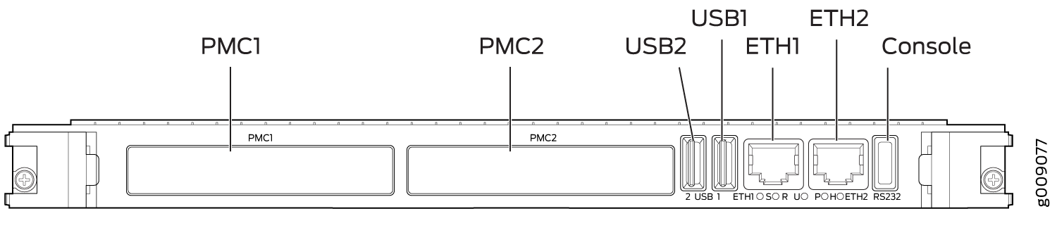
The front panel of the PP833 processor comprises the following components (see Figure 2):
-
PMC—Both PMC slots are available to support compatible fiber PMC modules. For more information about the PMC module, see CTP2000 PMC Module and Installing a PMC on CTP2000 Platforms.
-
Ethernet connection—Provides the 1-Gbps Ethernet connection to the IP network by means of a local Ethernet switch or router.
-
Console connection—Provides an asynchronous tty connection for locally configuring the CTP Series device. Because of front panel space limitations, the PP833 processor provides an RS232 serial console via a supplied USB-to-DB9 cable (p/n 720-071594), in which the DB-9 connector has the same pinout as a standard RS-232 DTE port.
The PP833 processor does not support XMC card.