ON THIS PAGE
Maintaining the EX9200 Host Subsystem
Taking the Host Subsystem Offline in an EX9200 Switch
Before removing a Routing Engine module (RE module) from an EX9200 switch, take the host subsystem offline.
The host subsystem performs switching and system management functions in an EX9200 switch.
To take a host subsystem offline:
The Switch Fabric module (SF module) might continue forwarding traffic for approximately 5 minutes after the request system halt command has been issued.
Replacing SSDs on EX9200-RE2
Replacing SSDs on EX9200-RE2
A base configuration (single RE configuration) EX9204 and EX9208 switch has one host subsystem. A redundant configuration (dual RE configuration) EX9204 and EX9208 switch has a second host subsystem. A base configuration (single RE configuration) EX9214 switch has two host subsystems. A redundant configuration (dual RE configuration) EX9214 switch has a third host subsystem. Each host subsystem has one routing engine. So a switch with base configuration of one host subsystem has one routing engine; a switch with base configuration of two host subsytems has two routing engines etc. (EX9214 will have three host subsystem for two routing engines.)
Each EX9200-RE2 routing engine has two solid-stage drives (SSDs). The SSDs are installed in the slot labelled SSD1 and SSD2. The following figure shows the EX9200-RE2 module. The storage drive slots are annotated as 10 in the figure.
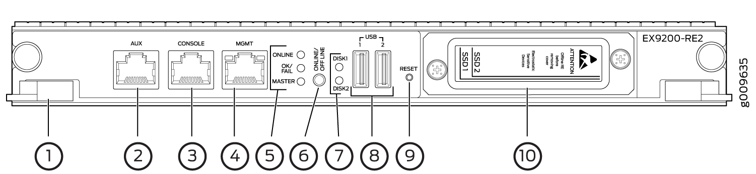
Extractor clips
Auxiliary port (AUX)
Console port (CONSOLE)
Management port (MGMT)
LEDs—ONLINE, OK/FAIL, and MASTER
ONLINE/OFFLINE button
SSD LEDs—DISK1 and DISK2
USB ports—USB1 and USB2
RESET button
SSD slots—SSD 1 and SSD 2
When replacing an SSD drive on an EX9200-RE2 Routing Engine on an EX9204, EX9208, and EX9214 with base configuration (single RE configuration) or redundant configuration (dual RE configuration), the procedure consists of two stages, namely, replacing the SSD Drive in the Routing Engine and copying vmhost and Junos OS to the replaced SSD.
Issue show vmhost hardware to check the disk size of the SSDs
before and after the upgrade. Refer show vmhost hardware.
Ensure to keep a bootable USB disk ready if installing vmhost and Junos OS using an USB disk. To prepare a bootable USB disk, see Creating an Emergency Boot Device for Routing Engines with VM Host Support.
- Replacing SSDs in the Routing Engine on an EX9204, EX9208, and EX9214 with base configuration (single RE configuration)
- Replacing SSDs on EX9200-RE2 on an EX9204, EX9208, and EX9214 with redundant configuration (dual RE configuration)
- Replacing an SSD Drive in the Routing Engine One at a Time
Replacing SSDs in the Routing Engine on an EX9204, EX9208, and EX9214 with base configuration (single RE configuration)
There will be a traffic hit during the SSD upgrade procedure for a switch with base configuration (single RE configuration) of one host subsystem (i.e. with a single routing engine).
To replace SSDs from the switch with only one routing engine:
Offline the Routing Engine by pressing the ONLINE/OFFLINE button. Hold the ONLINE/OFFLINE button until the LED starts blinking and wait until all routing engine LEDs are off.
Remove the SSDs:
Attach an ESD grounding strap to your bare wrist, and connect the strap to an ESD point on the appliance. For more information about ESD, see Preventing Electrostatic Discharge Damage in the hardware guide for your router.
Unfasten the thumbscrew that secures the access door in front of the storage drive slots, and open the door.
Slide the lock on the ejector to the unlocked position.
Carefully slide the drive out of the slot. See the following figure.
Figure 2: Removing an SSD in the EX9200-RE2 Routing Engine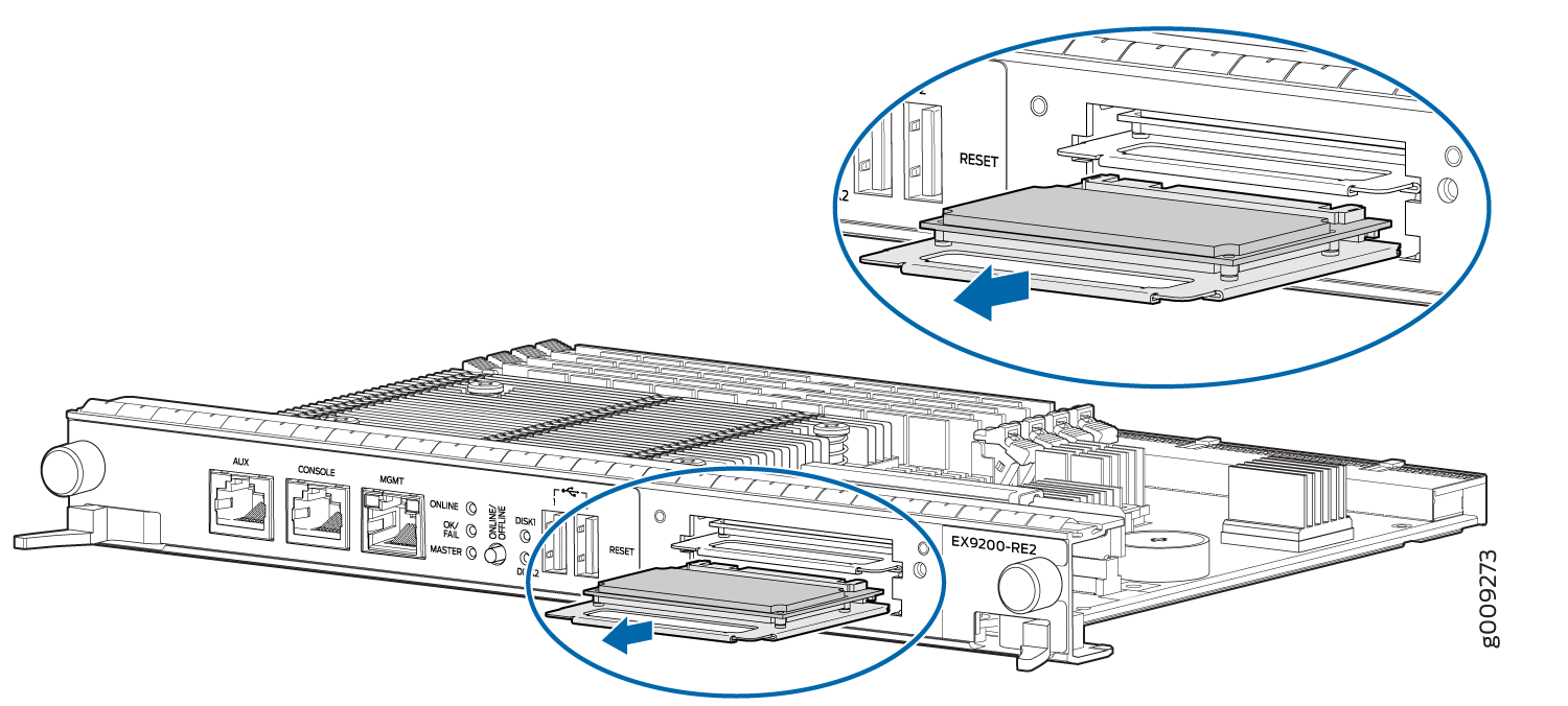
Reinstall with the upgraded SSDs:
Carefully align the sides of the drive with the guides in the slot.
Slide the drive into the slot until you feel resistance, carefully ensuring that it is correctly aligned.
Close the access door and tighten the thumbscrew to secure the door. See the following figure.
Figure 3: Installing the SSD in the EX9200-RE2 Routing Engine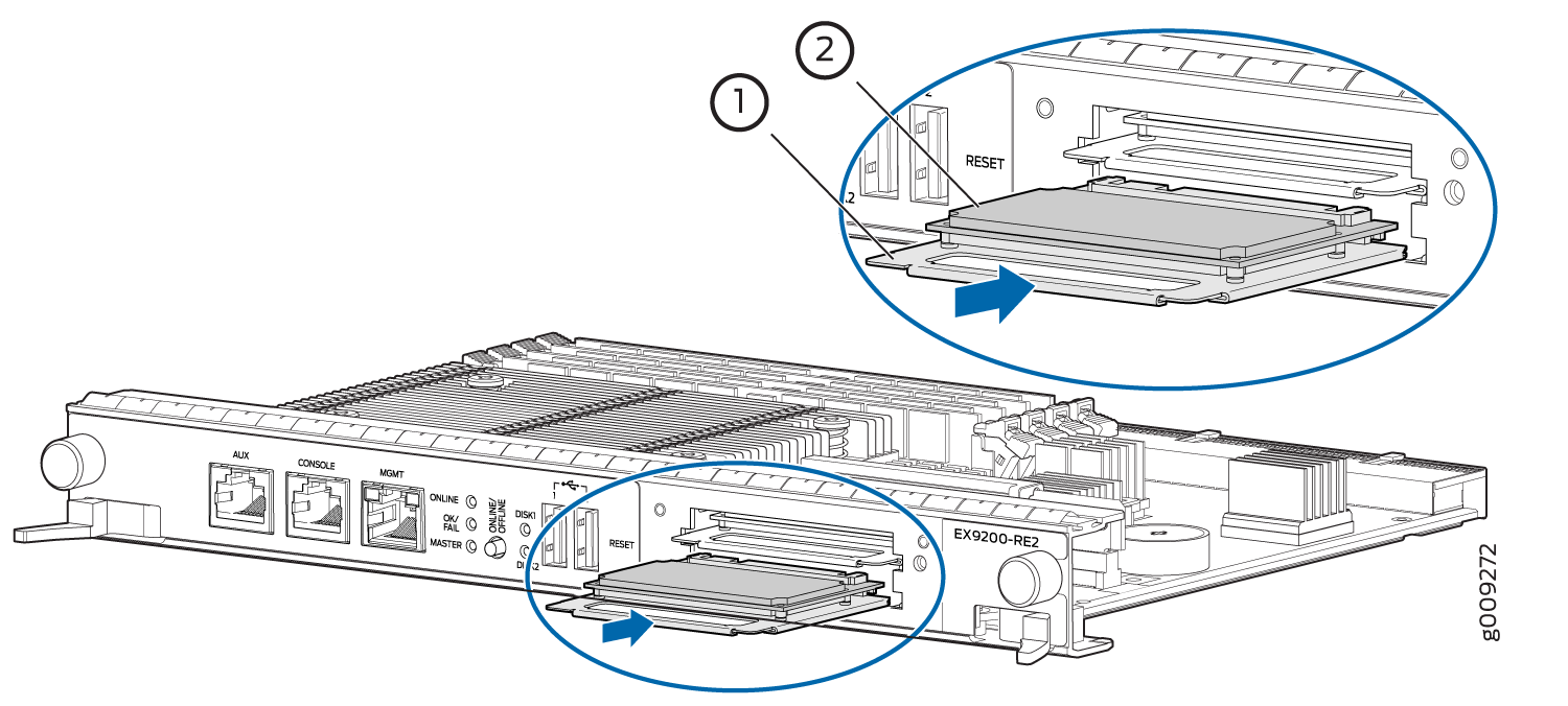
Copy Junos OS and vmhost to the upgraded SSDs. There are two ways to install Junos OS and vmhost on the routing engine.
Install Junos OS and vmhost using an USB disk
Install Junos OS and vmhost using the PXE Boot method.
Install Junos OS and vmhost using an USB disk:
Insert the USB disk in the USB slot on the routing engine.
Login to the routing engine through the console session.
Bring the routing engine online by pressing the ONLINE/OFFLINE button.
After the routing engine boots from the USB, press y when you are prompted to confirm
Install vmhost and Junos software on Primary and Secondary disk [y/N?on the console.After the installation is completed, press y when prompted to confirm
Reboot now? [y/N]?to reboot from the SSD disk.
Note:To prepare a bootable USB disk, see Creating an Emergency Boot Device for Routing Engines with VM Host Support.
Install Junos OS and vmhost using the PXE boot method:
Set up the PXE boot server. See Copying VM Host Installation Package to the PXE Boot Server.
Bring the routing engine online by pressing the ONLINE/OFFLINE button.
During the boot, when you see the message
Press Esc for boot optionspress Esc key to enter into the BIOS menu boot options. After the Esc key is pressed, Esc is pressed.Go to boot options. is displayed on the screen.Using Up or Down arrow keys, navigate to Boot Manager and press the Enter key.
Using Up or Down arrow keys, navigate through the EFI boot devices listed and select EFI Network 0 for IPv4 to boot from the PXE boot server and press the Enter key.
Booting `net boot consoleis displayed and PXE boot continues.Note:The booting process may take several minutes.
After the routing engine boots, press y when you are prompted to confirm
Install vmhost and Junos software on Primary and Secondary disk [y/N?on the console.After the installation is completed, press y when prompted to confirm
Reboot now? [y/N]?to reboot from the SSD disk.
Ensure that a routing engine does not contain a mix of 50 GB and 200 GB SSDs. Ensure that the SSDs on a routing engine are from the same vendor and not from different vendors. Both SSDs in the routing engine must be the same type and must contain the same disk capacity. So upgrade the two 50 GB SSDs to 200 GB SSDs at once, because mixed-mode operation is not supported.
Replacing SSDs on EX9200-RE2 on an EX9204, EX9208, and EX9214 with redundant configuration (dual RE configuration)
To replace SSDs in the switch that is using redundant routing engines:
Configure the
set chassis redundancy gracefulswitchover,set system commit synchronize, andset routing-options nonstop-routingcommands to enable graceful switchover (GRES), commit synchronize (required for nonstop routing) and nonstop routing (NSR).Bring the backup routing engine offline by pressing the ONLINE/OFFLINE button. Hold the ONLINE/OFFLINE button until the LED starts blinking and wait until all routing engine LEDs are off.
From the backup routing engine, remove the SSDs.
Attach an ESD grounding strap to your bare wrist, and connect the strap to an ESD point on the appliance.
For more information about ESD, see Preventing Electrostatic Discharge Damage in the hardware guide for your router.
Unfasten the thumbscrew that secures the access door in front of the storage drive slots and open the door.
Slide the lock on the ejector to the unlocked position.
Carefully slide the drives out of the slot. See the following figure..
Figure 4: Removing an SSD in the EX9200-RE2 Routing Engine
Install the upgraded SSDs:
Carefully align the sides of the drive with the guides in the slot.
See the following figure.
Figure 5: Installing the SSD in the EX9200-RE2 Routing Engine
Slide the drive into the slot until you feel resistance, carefully ensuring that it is correctly aligned.
Close the access door and tighten the thumbscrew to secure the door.
Copy Junos OS to the newly replaced SSDs. There are two ways to install Junos OS and vmhost on the routing engine.
Install Junos OS and vmhost using an USB disk
Install Junos OS and vmhost using the PXE Boot method.
Install Junos OS and vmhost using an USB disk:
Insert the USB disk in the USB slot on the routing engine.
Login to the routing engine through the console session.
Bring the routing engine online by pressing the ONLINE/OFFLINE button.
After the routing engine boots from the USB, press y when you are prompted to confirm
Install vmhost and Junos software on Primary and Secondary disk [y/N?on the console.After the installation is completed, press y when prompted to confirm
Reboot now? [y/N]?to reboot from the SSD disk.
Note:To prepare a bootable USB disk, see Creating an Emergency Boot Device for Routing Engines with VM Host Support.
Install Junos OS and vmhost using the PXE boot method:
Set up the PXE boot server. See Copying VM Host Installation Package to the PXE Boot Server.
Bring the routing engine online by pressing the ONLINE/OFFLINE button.
During the boot, when you see the message
Press Esc for boot optionspress Esc key to enter into the BIOS menu boot options. After the Esc key is pressed, Esc is pressed.Go to boot options. is displayed on the screen.Using Up or Down arrow keys, navigate to Boot Manager and press the Enter key.
Using Up or Down arrow keys, navigate through the EFI boot devices listed and select EFI Network 0 for IPv4 to boot from the PXE boot server and press the Enter key.
Booting `net boot consoleis displayed and PXE boot continues.Note:The booting process may take several minutes.
After the routing engine boots, press y when you are prompted to confirm
Install vmhost and Junos software on Primary and Secondary disk [y/N?on the console.After the installation is completed, press y when prompted to confirm
Reboot now? [y/N]?to reboot from the SSD disk.
Log in to the backup routing engine through the console session.
Bring the backup routing engine online by pressing the ONLINE/OFFLINE button.
After the backup routing engine starts booting from the USB, press y when you are prompted to confirm
Install vmhost and Junos software on Primary and Secondary disk [y/N?]on the console.After the installation completes, press y when prompted to confirm
Reboot now? [y/N]?to reboot from the SSD disk.Once the backup Routing Engine boots:
Verify if the backup Routing Engine is online by entering the
show chassis routing-engineCLI.Verify the new SSDs capacity by entering the
show vmhost hardwareCLI.Enter
show vmhost versionto verify that the vmhost versions are the same as the primary Routing Engine.From the primary Routing Engine, perform
commit synchronizecommand.If the Network Services Mode: Enhanced-IP configuration was previously applied, then a warning message indicating the changes in the network services mode displays. Perform a reboot on the backup Routing Engine in order to enable the Network Services Mode to apply Enhanced IP.
Ensure both the Routing Engines (primary and backup) are in sync and ready for the switchover:
On the backup Routing Engine, verify the GRES readiness by entering the
show system switchoverCLI.On the primary Routing Engine check the switchover state by entering
request chassis routing-engine master switch check.On the primary Routing Engine, check the replication state if nonstop-routing is enabled by entering the
show task replicationCLI.
Switch the current primary Routing Engine to become the backup Routing Engine and vice-versa by executing the
request chassis routing-engine master switchcommand on the current primary Routing Engine.Once the Routing Engine which was previously the back-up Routing Engine becomes the primary Routing Engine and is carrying traffic, repeat the steps on the new backup Routing Engine (which was previously the primary Routing Engine).
Ensure that the routing engine does not contain a mix of 50 GB and 200 GB SSDs. Ensure that the SSDs are from the same vendor and not from different vendors. Both SSDs in the routing engine must be the same type and must contain the same disk capacity. So upgrade the two 50 GB SSDs to 200 GB SSDs at once.
Ensure that the routing does not contain 200 GB SSDs from different vendors.
Replacing an SSD Drive in the Routing Engine One at a Time
During an upgrade procedure, you have to upgrade both SSDs at once. But there could be a situation when for example one of the two 200GB SSDs fails, and needs to be replaced. The following are the instructions to replace that SSD.
There will be a traffic hit during the SSD upgrade procedure for a switch with base configuration of one host subsystem (i.e. using one routing engine)
To replace an SSD in the slot labeled:
-
Disk 2
Disk 1
Ensure that there is no
VMHost %d Boot from alternate diskalarm in the output:user@host>show chassis alarmEnsure that the router is booted up and running from an image from disk 1. Back up the currently running vmhost and Junos OS on disk 1 to ensure that both disk 1 and disk 2 have the same version of vmhost and Junos OS:
user@host> request vmhost snapshot [partition]Reboot the router from disk 2:
user@host> request vmhost reboot disk2Check for the presence of the
VMHost %d Boot from alternate diskalarm in the output:user@host>show chassis alarm
Offline the Routing Engine by pressing the ONLINE/OFFLINE button. Hold the ONLINE/OFFLINE button until the LED starts blinking and wait until all routing engine LEDs are off.
Remove the SSD:
Attach an ESD grounding strap to your bare wrist, and connect the strap to an ESD point on the appliance. For more information about ESD, see Preventing Electrostatic Discharge Damage in the hardware guide for your router.
Unfasten the thumbscrew that secures the access door in front of the storage drive slots, and open the door.
Slide the lock on the ejector to the unlocked position.
Carefully slide the drive out of the slot. See the following figure.
Figure 6: Removing an SSD in the EX9200-RE2 Routing Engine
Note:Ensure that a routing engine does not contain a mix of 50 GB and 200 GB SSDs. Ensure that the SSDs on a routing engine are from the same vendor and not from different vendors. Both SSDs in the routing engine must be the same type and must contain the same disk capacity.
Reinstall the SSD:
Carefully align the sides of the drive with the guides in the slot.
Slide the drive into the slot until you feel resistance, carefully ensuring that it is correctly aligned.
Close the access door and tighten the thumbscrew to secure the door. See the following figure.
Figure 7: Installing the SSD in the EX9200-RE2 Routing Engine
Copy Junos OS to the newly replaced SSD. There are two ways to install Junos OS and vmhost on the routing engine.
Install Junos OS and vmhost using an USB disk
Install Junos OS and vmhost using the PXE Boot method.
Install Junos OS and vmhost using an USB disk:
Insert the USB disk in the USB slot on the routing engine.
Login to the routing engine through the console session.
Bring the routing engine online by pressing the ONLINE/OFFLINE button.
After the routing engine boots from the USB, press y when you are prompted to confirm
Install vmhost and Junos
                                        software on Primary and Secondary disk [y/N?
on the console.After the installation is completed, press y when prompted to confirm
Reboot now? [y/N]?to reboot from the SSD disk.
Note:To prepare a bootable USB disk, see Creating an Emergency Boot Device for Routing Engines with VM Host Support.
Install Junos OS and vmhost using the PXE boot method:
Set up the PXE boot server. See Copying VM Host Installation Package to the PXE Boot Server.
Bring the routing engine online by pressing the ONLINE/OFFLINE button.
During the boot, when you see the message
Press Esc for
                                        boot options
press Esc key to enter into the BIOS menu boot options. After the Esc key is pressed, Esc is pressed.Go to boot options. is displayed on the screen.Using Up or Down arrow keys, navigate to Boot Manager and press the Enter key.
Using Up or Down arrow keys, navigate through the EFI boot devices listed and select EFI Network 0 for IPv4 to boot from the PXE boot server and press the Enter key.
Booting `net boot consoleis displayed and PXE boot continues.Note:The booting process may take several minutes.
After the routing engine boots, press y when you are prompted to confirm
Install vmhost and Junos software on Primary and
                                        Secondary disk [y/N?
on the console.After the installation is completed, press y when prompted to confirm
Reboot now? [y/N]?to reboot from the SSD disk.
Removing an RE Module from an EX9200 Switch
Before you begin to remove an RE module:
Ensure you understand how to prevent electrostatic discharge (ESD) damage. See Prevention of Electrostatic Discharge Damage.
Remove all the cables connected to the RE module.
Before you remove an RE module, you must take the host subsystem offline. If there is only one RE module installed in the switch, taking the host subsystem offline shuts down the switch.
If the RE module to be removed is functioning as the primary Routing Engine, switch it to be the backup Routing Engine before removing it.
Ensure that you have the following parts and tools available:
ESD grounding strap
Phillips (+) screwdrivers, number 1 and 2
Antistatic bag or antistatic mat
Do not lift the Routing Engine module (RE module) by holding the ejector levers. The levers cannot support the weight of the module. Lifting the module by the levers might bend the levers. Bent levers will prevent the RE module from being properly seated in the chassis.
To remove an RE module from an EX9200 switch:
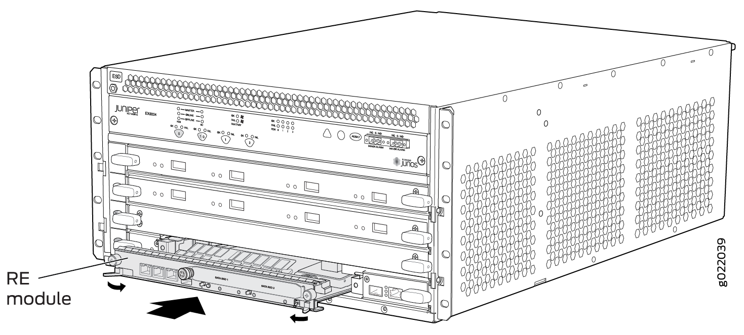
Figure 8 shows removing an RE module from an EX9204 switch. The procedure is the same for all EX9200 switches.

Installing an RE Module in an EX9200 Switch
Before you begin installing an RE module in an EX9200 switch:
Ensure you understand how to prevent electrostatic discharge (ESD) damage. See Prevention of Electrostatic Discharge Damage.
Ensure that you have the following parts and tools available to install an RE module:
ESD grounding strap
Phillips (+) screwdrivers, number 1 and 2
The Routing Engine module (RE module) in an EX9200 switch is a hot-insertable and hot-removable field-replaceable unit (FRU); you can remove and replace it while the switch is running without turning off power to the switch or disrupting switching functions. Each RE module is installed horizontally in a Switch Fabric module (SF module) installed in the switch.
In an EX9214 switch, you must install an RE module only in the SF modules installed in slots 7 and 8 labeled 0 and 1.
Do not lift the RE module by holding the ejector handles. The ejector handles cannot support the weight of the module. Lifting the ejector handles by the levers might bend the levers, and the bent ejector handles will prevent the RE module from being properly seated in the chassis.
To install an RE module in an EX9200 switch:
Figure 9 shows installing an RE module in an EX9204 switch. The procedure is the same for all EX9200 switches.
If you have a Juniper J-Care service contract, register any addition, change, or upgrade of hardware components at https://www.juniper.net/customers/support/tools/updateinstallbase/ . Failure to do so can result in significant delays if you need replacement parts. This note does not apply if you replace existing components with the same type of component.
See Also
Upgrading an EX9200-SF to an EX9200-SF2
For an EX9200 switch, if you want to upgrade the original SF module, EX9200-SF, with the high-speed SF module, EX9200-SF2, follow these steps:
- Preparing the EX9200 Switch for an EX9200-SF2 Upgrade
- Powering Off the Switch
- Removing a Routing Engine from an EX9200-SF Module
- Replacing the EX9200-SF with the EX9200-SF2
- Installing a Routing Engine into an EX9200-SF2
- Powering On the Switch
- Completing the EX9200-SF2 Upgrade
Preparing the EX9200 Switch for an EX9200-SF2 Upgrade
To prepare the switch for the upgrade:
Powering Off the Switch
You must power off the switch before you install EX9200-SF2. See Powering Off an EX9200 Switch.
Removing a Routing Engine from an EX9200-SF Module
To remove a Routing Engine from the EX9200-SF:
- Remove the cables connected to the Routing Engine.
- Place an electrostatic bag or antistatic mat on a flat, stable surface.
- Attach an electrostatic discharge (ESD) grounding strap to your bare wrist, and connect the strap to one of the ESD points on the chassis.
- Loosen the captive screws on the top and bottom of the Routing Engine.
- Flip the ejector handles outward to unseat the Routing Engine.
- Grasp the Routing Engine by the ejector handles, and slide it about halfway out of the chassis.
- Place one hand underneath the Routing Engine to support it, and slide it completely out of the chassis.
- Place the Routing Engine on the antistatic mat.
Replacing the EX9200-SF with the EX9200-SF2
To replace the existing EX9200-SF with the EX9200-SF2:
- Attach an electrostatic discharge (ESD) grounding strap to your bare wrist and connect the strap to one of the ESD points on the chassis.
- Remove and replace the offline EX9200-SF with the EX9200-SF2.
Installing a Routing Engine into an EX9200-SF2
To install a Routing Engine into an EX9200-SF2:
Powering On the Switch
Completing the EX9200-SF2 Upgrade
To complete the upgrade procedure:
Upgrading to an EX9200-SF3
If you are upgrading to the EX9200-SF3 from an older SF module, the Routing Engine must be upgraded to the first supported Junos release for the EX9200-SF3 (20.3.R1) before you install it in the EX9200-SF3. Also, we recommend that you update the recovery snapshot with the 20.3R1 or later image before you begin the upgrade. If the Routing Engine fails to boot from the primary image, it will attempt to boot from the recovery image. Since the older recovery image does not support the EX9200-SF3, the Routing Engine will crash if it attempts to boot from the old recovery image.
If you plug the Routing Engine into the EX9200-SF3
without first upgrading Junos to 20.3R1 or later, Junos might crash
and go to a db prompt. Should this occur, you’ll
need to recover the router by copying the Junos software image for
the 20.3R1 or later release and then booting from the USB drive to
install 20.3R1 Junos on the EX9200-SF3. The USB install will wipe
out the router configuration and all user files on the Routing Engine.
- Preparing the EX9200 Switch for an EX9200-SF3 Upgrade
- Powering Off the Switch
- Removing a Routing Engine from an SF Module
- Replacing the EX9200-SF or EX9200-SF2 with the EX9200-SF3
- Installing a Routing Engine into an EX9200-SF3
- Powering On the Switch
- Completing the EX9200-SF3 Upgrade
Preparing the EX9200 Switch for an EX9200-SF3 Upgrade
To prepare the switch for the upgrade:
Powering Off the Switch
You must power off the switch before you install EX9200-SF3. See Powering Off an EX9200 Switch.
Removing a Routing Engine from an SF Module
To remove a Routing Engine from an SF Module:
- Remove the cables connected to the Routing Engine.
- Place an electrostatic bag or antistatic mat on a flat, stable surface.
- Attach an electrostatic discharge (ESD) grounding strap to your bare wrist, and connect the strap to one of the ESD points on the chassis.
- Loosen the captive screws on the top and bottom of the Routing Engine.
- Flip the ejector handles outward to unseat the Routing Engine.
- Grasp the Routing Engine by the ejector handles, and slide it about halfway out of the chassis.
- Place one hand underneath the Routing Engine to support it, and slide it completely out of the chassis.
- Place the Routing Engine on the antistatic mat.
Replacing the EX9200-SF or EX9200-SF2 with the EX9200-SF3
To replace the existing SF module with the EX9200-SF3:
- Attach an electrostatic discharge (ESD) grounding strap to your bare wrist and connect the strap to one of the ESD points on the chassis.
- Remove and replace the offline SF module with the EX9200-SF3.
Installing a Routing Engine into an EX9200-SF3
To install a Routing Engine into an EX9200-SF3:
- Attach an electrostatic discharge (ESD) grounding strap to your bare wrist, and connect the strap to one of the ESD points on the chassis.
- Ensure that the ejector handles are not in the locked position. If necessary, flip the ejector handles outward.
- Place one hand underneath the Routing Engine to support it.
- Carefully align the sides of the Routing Engine with the guides inside the opening on the EX9200-SF3.
- Slide the Routing Engine into the EX9200-SF3 until you feel resistance, and then press the faceplate of the Routing Engine until it engages the connectors.
- Press both of the ejector handles inward to seat the Routing Engine.
- Tighten the captive screws on the top and bottom of the Routing Engine.
- Connect the management device cables to the Routing Engine.
Powering On the Switch
Completing the EX9200-SF3 Upgrade
To complete the upgrade procedure:
Removing an SF Module from an EX9200 Switch
Before you begin to remove an SF module:
Ensure you understand how to prevent electrostatic discharge (ESD) damage. See Prevention of Electrostatic Discharge Damage.
Ensure that you have the following parts and tools available:
ESD grounding strap
Antistatic bag or antistatic mat
Replacement SF module or cover panel for the slot
You must remove the Switch Fabric module (SF module) from an EX9200 switch if you need to replace the module or if you need to remove the switch components before moving the chassis without using a mechanical lift. You can remove the SF module and the Routing Engine module (RE module) as a unit, or remove the RE module separately.
Do not lift the SF module by holding the ejector levers. The levers cannot support the weight of the module. Lifting the modules by the levers might bend the levers. Bent levers will prevent the SF module from being properly seated in the chassis.
Before you replace an SF module, you must take the host subsystem offline. If there is only one host subsystem, taking the host subsystem offline shuts down the switch.
To remove an SF module:
Figure 10 shows removing an SF module from an EX9208 switch. The procedure is the same for all EX9200 switches.
Installing an SF Module in an EX9200 Switch
Before you begin installing an SF module:
Ensure you understand how to prevent electrostatic discharge (ESD) damage. See Prevention of Electrostatic Discharge Damage.
Ensure that you have the following parts and tools available:
ESD grounding strap
The Switch Fabric module (SF module) in an EX9200 switch is a hot-insertable and hot-removable field-replaceable unit (FRU); You can remove and replace it while the switch is running without turning off power to the switch or disrupting switching functions.
Do not lift the SF module by holding the ejector handles. The ejector handles cannot support the weight of the module. Lifting the module by the ejector handles might bend the ejector handles. Bent ejector handles prevent the SF module from being properly seated in the chassis.
To install an SF module:
Figure 11 shows installing an SF module in an EX9208 switch. The procedure is the same for all EX9200 switches.
If you have a Juniper J-Care service contract, register any addition, change, or upgrade of hardware components at https://www.juniper.net/customers/support/tools/updateinstallbase/ . Failure to do so can result in significant delays if you need replacement parts. This note does not apply if you replace existing components with the same type of component.
See Also
Maintaining the Host Subsystem in EX9200 Switches
Purpose
For optimum performance of an EX9200 switch, verify the condition of the host subsystem. The host subsystem comprises a Switch Fabric and a Routing Engine. Routing Engine module (RE module) is installed directly into a Switch Fabric module (SF module).
Action
On a regular basis:
Check the LEDs on the craft interface to view information about the status of the Routing Engines.
Check the LEDs on the SF module faceplate.
Check the LEDs on the RE module faceplate.
To check the status of the Routing Engines, issue the
show chassis routing-enginecommand. The output is similar to the following:user@switch> show chassis routing-engine Routing Engine status: Slot 0: Current state Master Election priority Master (default) Temperature 31 degrees C / 87 degrees F CPU temperature 30 degrees C / 86 degrees F DRAM 3313 MB (8192 MB installed) Memory utilization 56 percent CPU utilization: User 78 percent Background 0 percent Kernel 21 percent Interrupt 1 percent Idle 0 percent Model RE-S-EX9200-1800X4 Serial ID 9009114067 Start time 2013-02-22 22:28:07 PST Uptime 2 days, 3 hours, 38 minutes, 48 seconds Last reboot reason Router rebooted after a normal shutdown. Load averages: 1 minute 5 minute 15 minute 0.79 0.49 0.42 Routing Engine status: Slot 1: Current state Backup Election priority Backup (default) Temperature 33 degrees C / 91 degrees F CPU temperature 31 degrees C / 87 degrees F DRAM 3313 MB (16384 MB installed) Memory utilization 28 percent CPU utilization: User 6 percent Background 0 percent Kernel 6 percent Interrupt 1 percent Idle 88 percent Model RE-S-EX9200-1800X4 Serial ID 9009118544 Start time 2013-02-22 22:27:58 PST Uptime 2 days, 3 hours, 38 minutes, 44 seconds Last reboot reason Router rebooted after a normal shutdown. Load averages: 1 minute 5 minute 15 minute 0.06 0.02 0.00The output is of an EX9208 switch. The output is similar for all EX9200 switches.
To check the status of the Switch Fabrics, issue the
show chassis environment cbcommand. The output is similar to the following:user@switch> show chassis environment cb CB 0 status: State Online Master Temperature 30 degrees C / 86 degrees F Power 1 1.0 V 1005 mV 1.2 V 1218 mV 1.5 V 1475 mV 1.8 V 1830 mV 2.5 V 2520 mV 3.3 V 3345 mV 5.0 V 5053 mV 5.0 V RE 4962 mV 12.0 V 12220 mV 12.0 V RE 12123 mV Power 2 4.6 V bias MidPlane 4840 mV 11.3 V bias PEM 11176 mV 11.3 V bias FPD 11292 mV 11.3 V bias POE 0 11272 mV 11.3 V bias POE 1 11311 mV Bus Revision 64 FPGA Revision 13 PMBus Expected Measured Measured Calculated device voltage voltage current power XF ASIC A 1000 mV 998 mV 13609 mA 13581 mW XF ASIC B 1000 mV 1000 mV 12390 mA 12390 mW CB 1 status: State Online Standby Temperature 30 degrees C / 86 degrees F Power 1 1.0 V 1002 mV 1.2 V 1214 mV 1.5 V 1472 mV 1.8 V 1804 mV 2.5 V 2520 mV 3.3 V 3325 mV 5.0 V 5053 mV 5.0 V RE 4969 mV 12.0 V 12239 mV 12.0 V RE 12239 mV Power 2 4.6 V bias MidPlane 4840 mV 11.3 V bias PEM 11176 mV 11.3 V bias FPD 11234 mV 11.3 V bias POE 0 11176 mV 11.3 V bias POE 1 11214 mV Bus Revision 64 FPGA Revision 13 PMBus Expected Measured Measured Calculated device voltage voltage current power XF ASIC A 1000 mV 1002 mV 11234 mA 11256 mW XF ASIC B 1000 mV 998 mV 11000 mA 10978 mWThe output is of an EX9208 switch. The output is similar for all EX9200 switches.
To check the status of a specific Switch Fabric, issue the show chassis environment cb command and include the slot number
of the SF. The output is similar to the following:
user@switch> show chassis environment cb 0
CB 0 status:
  State                      Online Master
  Temperature                30 degrees C / 86 degrees F
  Power 1
    1.0 V                     1002 mV
    1.2 V                     1218 mV
    1.5 V                     1475 mV
    1.8 V                     1827 mV
    2.5 V                     2526 mV
    3.3 V                     3338 mV
    5.0 V                     5053 mV
    5.0 V RE                  4969 mV
    12.0 V                   12220 mV
    12.0 V RE                12123 mV
  Power 2
    4.6 V bias MidPlane       4840 mV
    11.3 V bias PEM          11176 mV
    11.3 V bias FPD          11292 mV
    11.3 V bias POE 0        11272 mV
    11.3 V bias POE 1        11311 mV
  Bus Revision               64
  FPGA Revision              13
  PMBus             Expected   Measured   Measured  Calculated
  device            voltage    voltage    current   power
    XF ASIC A        1000 mV     997 mV   13609 mA   13568 mW
    XF ASIC B        1000 mV    1000 mV   12484 mA   12484 mW
The output is of an EX9208 switch. The output is similar for all EX9200 switches.
For more information about using the CLI, see the Junos OS documentation.