- play_arrow Fast Track: Initial Installation
- play_arrow Overview
- play_arrow MX2010 Router Overview
- play_arrow Chassis Components and Descriptions
- MX Series Router Architecture
- MX2010 Chassis Description
- MX2010 Backplane Description
- MX2010 Component Redundancy
- MX2010 Field-Replaceable Units
- MX Series Router Packet Forwarding Engine (PFE) Architecture
- Line Cards Supported on MX Series Routers
- Ethernet Frame Counts and Statistics on MX Series Routers
- Understanding Trio Layer 2 Feature Parity
- MX2010 Router Hardware Components and CLI Terminology
- play_arrow Alarm and Display Components
- play_arrow Cable and Rack Management
- play_arrow Cooling System
- play_arrow Host Subsystem Components
- MX2000 Host Subsystem CB-RE Description
- RE-MX2000-1800x4 CB-RE Description
- REMX2K-X8-64G and REMX2K-X8-64G-LT CB-RE Description
- REMX2K-X8-128G CB-RE Description
- CB-RE LEDs
- MX2000 Switch Fabric Board (SFB) Overview
- MX2000-SFB-S Switch Fabric Board Description
- MX2000-SFB2-S Enhanced Switch Fabric Board Description
- MX2000-SFB3 Switch Fabric Board Description
- MX2000 Switch Fabric Board LED
- play_arrow Interface Modules— ADCs, MPCs, and MICs
- MX Series Interface Module Reference
- MX2000 Adapter Card (ADC) Description
- MX2010 Modular Port Concentrator Description
- MPCs Supported by MX Series Routers
- MX2010 Modular Port Concentrator LEDs
- MX2010 MPC Terminology
- MX2010 Modular Interface Card Description
- MICs Supported by MX Series Routers
- MX2010 Modular Interface Card LEDs
- MX2010 Port and Interface Numbering
- play_arrow Power System
- MX2010 Power System Description
- MX2010 Power Midplane Description
- MX2000 Three-Phase Delta AC Power Distribution Module Description
- MX2000 Three-Phase Wye AC Power Distribution Module Description
- MX2000 Seven-Feed Single-Phase AC Power Distribution Module Description
- MX2000 Nine-Feed Single-Phase AC Power Distribution Module Description
- MX2000 Three-Phase Delta and Wye AC Power Distribution Module LEDs
- MX2000 AC Power Supply Module Description
- MX2010 AC Power Supply Module LEDs
- MX2010 DC Power Distribution Module (-48 V) Description
- MX2000 DC Power Distribution Module (240 V China) Description
- MX2010 DC Power Distribution Module (-48 V) LEDs
- MX2000 DC Power Distribution Module (240 V China) LEDs
- MX2010 DC Power Supply Module (-48 V) Description
- MX2000 DC Power Supply Module (240 V China) Description
- MX2010 DC Power Supply Module LEDs
- MX2010 High-Voltage Universal (HVAC/HVDC) Power Distribution Module Description
- MX2010 High-Voltage Universal (HVAC/HVDC) Power Distribution Module LEDs
- MX2010 High-Voltage Universal (HVAC/HVDC) Power Supply Module Description
- MX2010 High-Voltage Universal (HVAC/HVDC) Power Supply Module LEDs
-
- play_arrow Site Planning, Preparation, and Specifications
- play_arrow Planning and Preparing the Site
- Overview of Preparing the Site for the MX2010 Router
- MX2010 Cabinet Airflow Requirements
- MX2010 Cabinet Size and Clearance Requirements
- MX2010 Chassis Moving Guidelines
- MX2010 Physical Specifications
- MX2010 Rack Requirements
- MX2010 Router Transport Kit Moving Requirements and Guidelines
- MX2010 Router Environmental Specifications
- MX2000 Router Grounding Specifications
- MX2010 Site Preparation Checklist
- Clearance Requirements for Airflow and Hardware Maintenance for the MX2010 Router
- play_arrow Transceiver and Cable Specifications
- play_arrow Pinout Specifications
- play_arrow AC Power Requirements, Specifications, and Guidelines
- MX2010 AC Power Requirements
- MX2000 AC Power Cord Specifications
- MX2000 AC Power System Electrical Specifications
- MX2000 Router Grounding Specifications
- MX2000 Three-Phase Delta AC Power Distribution Module Electrical Specifications
- MX2000 Three-Phase Wye AC Power Distribution Module Electrical Specifications
- MX2000 Single-Phase AC Power Distribution Module Electrical Specifications
- Calculating AC Power Requirements for MX2010 Routers
- Mapping Input Power from AC Power Distribution Modules to AC Power Supply Modules on MX2000 Routers
- play_arrow DC Power Requirements, Specifications, and Guidelines
- MX2010 DC Power Requirements
- MX2010 DC Power Distribution Description (-48 V)
- MX2010 DC Power Distribution (240 V China) Description
- MX2010 DC Power (-48 V) System Electrical Specifications
- MX2010 Router DC (240 V China) System Electrical Specifications
- Calculating DC Power Requirements for MX2010 Routers
- DC Power (-48 V) Circuit Breaker Requirements for the MX2010 Router
- DC Power (240 V China) Circuit Breaker Requirements for the MX2000 Router
- DC Power Cable Specifications for the MX2010 Router
- play_arrow Universal (HVAC/HVDC) Power Requirements, Specifications, and Guidelines
- MX2010 High-Voltage Universal (HVAC/HVDC) Power Requirements
- MX2000 High-Voltage Universal PDM (MX2K-PDM-HV) Power Cord Specifications
- MX2000 Router High-Voltage Universal (HVAC/HVDC) Power Subsystem Electrical Specifications
- Determining High-Voltage Universal (HVAC/HVDC) Power Requirements for Your MX2010 Router
- High-Voltage Universal (HVAC/HVDC) Power Circuit Breaker Requirements for the MX2000 Router
-
- play_arrow Installing and Replacing Components
- play_arrow Installing Components
- Installing an MX2010 Adapter Card
- Installing the MX2010 Air Filter
- Installing the MX2010 Craft Interface
- Installing the MX2010 Standard DC Cable Manager
- Installing an MX2000 Router DC Power Distribution Module (-48 V)
- Installing an MX2000 Router DC Power Distribution Module (240 V China)
- Installing an MX2000 Router High-Voltage Universal (HVAC/HVDC) Power Distribution Module
- Installing an MX2010 DC Power Supply Module (-48 V)
- Installing MX2000 Router DC Power Supply Modules (240 V China)
- Installing MX2000 Router High-Voltage Universal (HVAC/HVDC) Power Supply Modules
- Installing an MX2010 Dual-Wide MIC
- Installing the MX2010 Standard EMI Cover
- Installing the MX2010 Extended EMI Cover
- Installing an MX2010 Fan Tray
- Installing the MX2010 Air Baffle
- Installing the MX2010 Standard Cable Manager
- Installing the MX2010 Extended Cable Manager
- Installing the MX2010 Extended DC Cable Manager
- Installing an MX2010 MIC
- Installing an MX2000 SFB
- Installing an MX2010 CB-RE
- Installing MX2000 Router AC Power Supply Modules
- Installing MX2000 Router DC Power Supply Modules (-48 V)
- Installing an MX2000 Router Three-Phase Delta AC Power Distribution Module
- Installing an MX2000 Router Three-Phase Wye AC Power Distribution Module
- Installing an MX2000 Single-Phase AC Power Distribution Module
- Installing an SFP or XFP into an MX2000 MPC or MIC
- play_arrow Replacing Components
- Tools and Parts Required for Replacing MX2010 Hardware Components
- Tools and Parts Required to Remove Components from an MX2010 Router
- Removing a CB-RE from an MX2000 Router
- Upgrading to the Control Board-Routing Engine REMX2K-X8-64G in a Redundant Host Subsystem
- Upgrading to the REMX2K-X8-64G CB-RE in a Nonredundant Host Subsystem
- Replacing a Cable on an MX2010 MPC or MIC
- Replacing the MX2010 Air Filters
- Replacing the MX2010 Standard Cable Managers
- Replacing the MX2010 Extended Cable Manager
- Replacing the MX2010 Craft Interface
- Replacing an MX2010 DC Power Supply Module (-48 V)
- Replacing an MX2000 DC Power Supply Module (240 V China)
- Replacing an MX2000 High-Voltage Second-Generation Universal (HVAC/HVDC) Power Supply Module
- Replacing an MX2000 DC Power Distribution Module (-48 V)
- Replacing an MX2000 DC Power Distribution Module (240 V China)
- Replacing an MX2000 High-Voltage Universal (HVAC/HVDC) Power Distribution Module
- Replacing an MX2010 DC Power Distribution Module Cable
- Connecting an MX2000 DC Router Power Distribution Module (240 V China) Cable
- Replacing the MX2010 Standard EMI Cover
- Replacing the MX2010 Extended EMI Cover
- Replacing an MX2010 Fan Tray
- Replacing the MX2010 Air Baffle
- Replacing an MX2010 MIC
- Replacing an MX2010 MPC and Adapter Card
- Replacing an MX2000 SFB
- Replacing an MX2000 CB-RE
- Replacing an SFP or XFP Transceiver on an MX2010 MPC or MIC
- Replacing an MX2000 AC Power Supply Module
- Replacing an MX2010 Three-Phase Delta AC Power Cord
- Replacing an MX2000 Three-Phase Delta AC Power Distribution Module
- Replacing an MX2010 Three-Phase Wye AC Power Cord
- Replacing an MX2020 Three-Phase Wye AC Power Distribution Module
-
- play_arrow Maintaining the Chassis and Components
- play_arrow Maintaining Components
- Maintaining the MX2010 Adapter Cards
- Maintaining Cables That Connect to MX2010 MPCs or MICs
- Maintaining and Verifying the Status of the MX2010 Router Components
- Maintaining the MX2010 Air Filters
- Maintaining the MX2010 Air Vents
- Maintaining the MX2010 Chassis FRU Power-On Sequence
- Maintaining the MX2010 Control Boards
- Maintaining the MX2010 Cooling System Components
- Maintaining the MX2010 Cooling System Zones
- Maintaining the MX2010 Ethernet Switch
- Maintaining the MX2010 Fan Trays
- Maintaining the MX2010 Air Baffle
- Maintaining the MX2010 Host Subsystem
- Maintaining MX2010 MICs
- Maintaining MX2010 MPCs
- Maintaining MX2010 Packet Forwarding Engine Components
- Maintaining the Power Supply Modules on the MX2000 Line of Routers
- Maintaining the MX2010 Power Usage
- Converting an MX2000 Router Between AC and DC Power
- Maintaining the MX2010 Routing Engines
- Maintaining the MX2010 SFB
- Maintaining the MX2010 Switch Processor Mezzanine Board (SPMB)
- Maintaining and Verifying the MX2010 Router Version
- Maintaining and Verifying the Status of the MX2010 Craft Interface
- Taking an MX2000 Host Subsystem Offline
- Holding an MX2010 MPC
- Storing an MX2010 MPC
- Routine Maintenance Procedures for the MX2010 Router
- play_arrow Packing and Returning Components
- play_arrow Powering Off the Router
-
- play_arrow Troubleshooting Hardware
- play_arrow Contacting Customer Support and Returning the Chassis or Components
- play_arrow Contacting Customer Support
- play_arrow Locating Component Serial Numbers
- Displaying MX2010 Router Components and Serial Numbers
- MX2010 CB-RE Serial Number Label
- MX2010 Chassis Serial Number Label
- MX2010 Craft Interface Serial Number Label
- MX2010 Fan Tray Serial Number Label
- MX2010 MIC Serial Number Label
- MX2010 MPC Serial Number Label
- MX2010 Power Distribution Module Serial Number Label
- MX2010 Power Supply Module Serial Number Label
- MX2010 SFB Serial Number Label
- play_arrow Packing and Returning Components
-
- play_arrow Safety and Compliance Information
- play_arrow General Safety Guidelines and Warnings
- play_arrow Installation and Maintenance Safety Guidelines and Warnings
- play_arrow Radiation and Laser Warnings
- play_arrow Maintenance and Operational Safety Guidelines and Warnings
- play_arrow Electrical Safety Guidelines and Warnings
- General Electrical Safety Guidelines and Warnings
- Prevention of Electrostatic Discharge Damage
- AC Power Electrical Safety Guidelines
- AC Power Disconnection Warning
- DC Power Copper Conductors Warning
- DC Power Disconnection Warning
- DC Power Grounding Requirements and Warning
- DC Power Wiring Sequence Warning
- DC Power Wiring Terminations Warning
- Midplane Energy Hazard Warning
- Multiple Power Supplies Disconnection Warning
- Action to Take After an Electrical Accident
- play_arrow Agency Approvals and Compliance Statements
-
Connecting the MX2010 Router to Management and Alarm Devices
Connecting the MX2010 Router to a Network for Out-of-Band Management
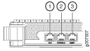
To connect the CB-RE to a network for out-of-band management, connect an Ethernet cable with RJ-45 connectors to the MGMT port on the CB-RE interface. To connect to the MGMT port on the CB-RE interface:
- Turn off power to the management device.
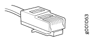
- Plug one end of the Ethernet cable (Figure 2 shows the connector) into the MGMT port on the CB-RE interface. Figure 1 shows the port. Table 1 describes the Ethernet ports.
- Plug the other end of the cable into the network device.


Function No. | Label | Description |
---|---|---|
3 | MGMT | Dedicated management channel for device maintenance. It is also used by system administrators to monitor and manage the MX2010 remotely. |
See Also
Connecting an MX2000 Router to a Console or Auxiliary Device
To use a system console to configure and manage the Routing Engine, connect it to the appropriate CONSOLE port on the RCB interface. To use a laptop, modem, or other auxiliary device, connect it to the AUX port on the RCB interface. Both ports accept a cable with an RJ-45 connector. To connect a device to the CONSOLE port and another device to the AUX port, you must supply two additional cables.
We no longer include the RJ-45 console cable with the DB-9 adapter as part of the device package. If the console cable and adapter are not included in your device package, or if you need a different type of adapter, you can order the following separately:
RJ-45 to DB-9 adapter (JNP-CBL-RJ45-DB9)
RJ-45 to USB-A adapter (JNP-CBL-RJ45-USBA)
RJ-45 to USB-C adapter (JNP-CBL-RJ45-USBC)
If you want to use RJ-45 to USB-A or RJ-45 to USB-C adapter you must have X64 (64-Bit) Virtual COM port (VCP) driver installed on your PC. See, https://ftdichip.com/drivers/vcp-drivers/ to download the driver.
The MX2000 router must be adequately grounded before powering on the console or auxiliary devices (see MX2000 Router Grounding Specifications).
To connect a management console or auxiliary device:

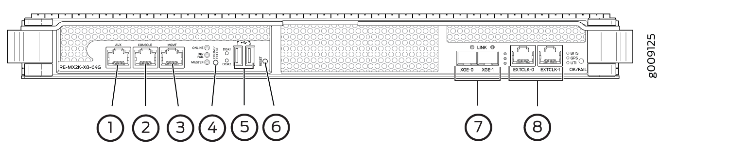
1 — AUX port | 5 — USB ports |
2 — CONSOLE port | 6 — RESET button |
3 — MGMT port | 7 — XGE-0 and XGE-1 ports |
4 — ONLINE/OFFLINE button | 8 — EXTCLK0 and EXTCLK1 ports |

Function No. | Label | Description |
---|---|---|
1 | AUX | Connect a laptop, modem, or other auxiliary unit. |
2 | CONSOLE | Connect a laptop or console terminal to configure the MX2000 router. |
Connecting an MX2010 Router to an External Alarm-Reporting Device
To connect the router to external alarm-reporting devices, attach wires to the RED and YELLOW relay contacts on the craft interface (see Figure 5). A system condition that triggers the red or yellow alarm LED on the craft interface also activates the corresponding alarm relay contact.
The terminal blocks that plug into the alarm relay contacts are supplied with the router (see Table 3). They accept wire of any gauge between 28 AWG and 14 AWG (0.08 and 2.08 mm2); the wire is not provided. Use the gauge of wire appropriate for the external device you are connecting.
To connect an external device to an alarm relay contact (see Figure 5):
- Prepare the required length of wire with gauge between 28 AWG and 14 AWG (0.08 and 2.08 mm2).
- While the terminal block is not plugged into the relay contact, use a 2.5-mm flat-blade screwdriver to loosen the small screws. With the small screws facing left, insert wires into the slots in the front of the block based on the wiring for the external device. Tighten the screws to secure the wire.
- Plug the terminal block into the relay contact, and use a 2.5-mm flat-blade screwdriver to tighten the screws on the face of the block.
- Attach the other end of the wires to the external device.
To attach a reporting device for the other kind of alarm, repeat the procedure.
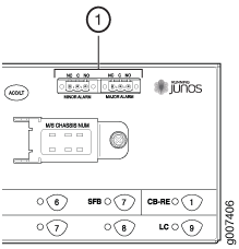
Function No. | Label | Description |
---|---|---|
1 | MINOR ALARM—[NC C NO] MAJOR ALARM—[NC C NO] | The alarm relays consist of three terminal contacts with normal closed (NC), common (C), and normal open (NO) relays that signal a minor or major alarm when broken. |