Upgrading to the RE-S-X6-64G Routing Engine in a Redundant Host Subsystem
A redundant host subsystem consists of a primary Routing Engine (RE0) and a backup Routing Engine (RE1). To upgrade the host subsystem to use the RE-S-X6-64G Routing Engine, you must first uninstall the backup Routing Engine and install the RE-S-X6-64G Routing Engine, which then becomes the backup Routing Engine. You then switch over this backup Routing Engine to make it the primary Routing Engine. Replace the other Routing Engine and configure it as the backup Routing Engine.
Ensure that the Switch Control Board in the chassis is SCBE2 or SCBE3 because the RE-S-X6-64G Routing Engine is not compatible with the Switch Control Boards SCB or SCBE. To upgrade the Switch Control Board to SCBE2, see Upgrading an MX240 to Use the SCBE2-MX, Upgrading an MX480 to Use the SCBE2-MX or Upgrading an MX960 to Use the SCBE2-MX, depending on the chassis on which the Routing Engine is being upgraded. To upgrade the Switch Control Board to SCBE3 Upgrading an MX240, MX480, or MX960 Router to Use the SCBE3-MX.
Save the router configuration before proceeding with the Routing Engine upgrade.
Nonstop active routing (NSR) and graceful Routing Engine
switchover (GRES) are not supported during the upgrade and they must
be temporarily disabled. Disable NSR by removing the nonstop-routing statement from the [edit routing-options] hierarchy level
and by removing the graceful-switchover statement from
the [edit chassis redundancy] hierarchy level .
Removing the Routing Engine
- On the external management device connected to the Routing
Engine, shut down the host subsystem by using the
request system
power-off
command. - Wait until a message appears on the console confirming that the operating system has halted.
- Remove the cables connected to the Routing Engine.
- Place an electrostatic bag or antistatic mat on a flat, stable surface. Attach an electrostatic discharge (ESD) grounding strap to your bare wrist and connect the strap to one of the ESD points on the chassis.
- Verify that the Routing Engine LEDs are off. Loosen the captive screws on the top and bottom of the Routing Engine.
- Grasp the Routing Engine by the ejector handles, and slide it about halfway out of the chassis.
- Place one hand underneath the Routing Engine to support it, and slide it completely out of the chassis. Place the Routing Engine on the antistatic mat.
To maintain proper airflow through the chassis, do not leave an SCB installed in the chassis without a Routing Engine for extended periods of time. If a Routing Engine is removed, a replacement Routing Engine should be installed as soon as possible.
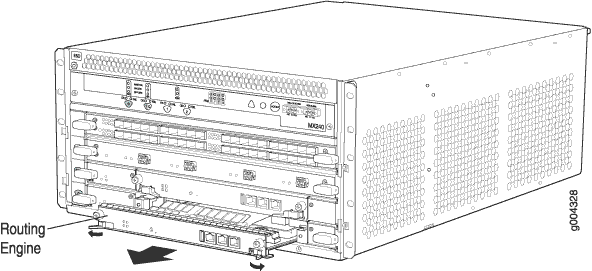
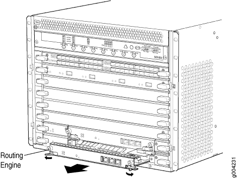
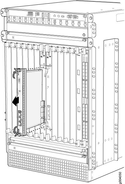
Installing the Routing Engine RE-S-X6-64G
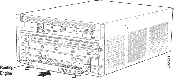
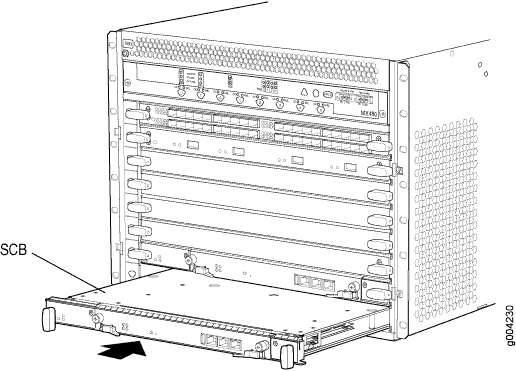
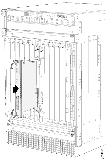
To install the Routing Engine RE-S-X6-64G:
The Routing Engine might require several minutes to boot. After the Routing Engine boots, verify that it is installed correctly by checking the FAIL, RE0, and RE1 LEDs on the craft interface. If the router is operational and the Routing Engine is functioning properly, the green ONLINE LED on the Routing Engine lights steadily. If the red FAIL LED on the Routing Engine lights steadily instead, remove and install the Routing Engine again. If the red FAIL LED still lights steadily, the Routing Engine is not functioning properly. Contact your customer support representative.
Verifying and Configuring the Upgraded Routing Engine as the Primary
After replacing the backup Routing Engine with the RE-S-X6-64G Routing Engine, perform the following steps:
-
Verify that the SCBE2 or SCBE3 and RE-S-X6-64G Routing Engine are online
by issuing the
show chassis hardwarecommand. - After you install the RE-S-X6-64G Routing Engine into the SCBE2 or SCBE3, the Routing Engine gets automatically powered on and comes up in amnesiac mode as it is loaded with factory defaults. After the Routing Engine comes up in amnesiac mode, load the base configuration and commit.
- Configure the backup Routing Engine by using the
commit synchronizecommand to copy the configuration to the backup Routing Engine. - Use the
request chassis routing-engine master switchcommand to make the Routing Engine RE-S-X6-64G (RE1) the primary Routing Engine. All FPCs reboot after this step.
Verifying and Configuring the Upgraded Routing Engine as the Backup
- Use the
request chassis routing-engine master switchcommand to make newly installed RE-S-X6-64G (RE0) the backup Routing Engine. - Use the
commit synchronizecommand to copy the active configuration from the primary Routing Engine to the backup Routing Engine.
