QFX5130 Power System
The power supply module in the QFX5130 models are hot-removable and hot-insertable field-replaceable units (FRUs). You can install replacement power supplies without powering off the device or disrupting the switching function. The power supplies are installed at the factory and shipped with the chassis. All power supplies for QFX5130 are 1600 watt (W).
Use only the power supply module that meet the wattage and airflow requirements for your model number. In a chassis, do not install power supplies modules with different airflow or wattage.The system raises an alarm when you insert a power supply <unit/module> that has a different airflow or wattage into the chassis.
The power supplies for the QFX5130 switch are located on the FRU panel. See Figure 1 and Figure 2.

1 — Power supplies | 2 — Fans |
Figure 2 shows the QFX5130-48C power supplies.
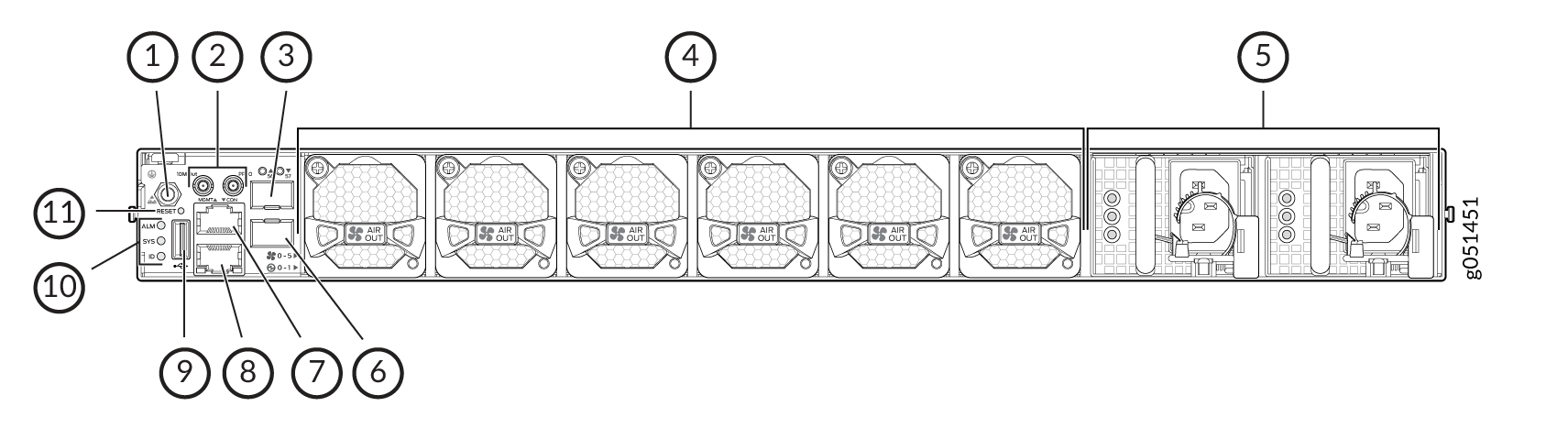
1 — ESD point | 7 — RJ-45 management port |
2 — Clock input and output connectors [10 megahertz (MHz) and 1 pulses per second (PPS)] | 8 — RJ-45 console port |
3 — 10GbE ports–SFP+ cages | 9 — USB slot |
4 — Fan modules | 10 — Chassis status LED |
5 — Power supplies | 11 — Reset button |
6 — 10GbE ports–SFP+ cages |
The power supply unit requires 2-3 seconds to display the output once it is powered on. When you use the 'power-off' command and there is a disruption in power supply (When input power turns off and on within 180 seconds from getting powered off), the power supply module on the chassis stops supplying power from the power supply module to the chassis.
QFX5130 Switch AC Power Supply Modules Description
QFX5130 switches ship with two power supplies. While QFX5130 switches can operate with the minimum number of power supplies, maximum power supplies are required to have redundancy. See Figure 3 that depicts an example of these power supplies.

An AC power supply for the QFX5130 switch is 1600 W.
The power supply provides FRU-to-port or port-to-FRU airflow depending on the model and variant you purchase. The power supplies have color-coded indicators to indicate the airflow direction.
Verify that the airflow direction on the power supply handle matches the direction of airflow in the chassis. Ensure that each power supply you install in the chassis has the same airflow direction. If you install power supplies with two different airflow directions, Junos OS raises an alarm. If you need to convert the airflow pattern on a chassis, you must change out all the fans and power supplies at one time to use the new direction.
To avoid electrical injury, carefully follow the instructions in Connect the QFX5130 Switch to Power.
QFX5130 AC Power Specifications
Table 1and Table 2 describe the AC power specifications for the QFX5130 switches.
Item |
Specification |
|---|---|
AC input voltage |
Operating range: 100 - 240 VAC |
AC input line frequency |
50/60 Hz |
AC input current rating |
100-127 VAC, 12A / 200-240 VAC, 8A |
Typical power consumption |
373 W |
Maximum power consumption |
839 W |
Item |
Specification |
|---|---|
AC input voltage |
Operating range: 100 - 127 VAC / 200 - 240 VAC |
AC input line frequency |
50/60 Hz |
AC input current rating |
100 -127 VAC, 12A / 200 - 240VAC, 9A |
Typical power consumption |
253 W |
Maximum power consumption |
641 W |
The QFX5130 AC model uses power cords with type C15 couplers. See AC Power Cord with Type C15 Coupler Specifications.
AC Power Cord with Type C15 Coupler Specifications
Detachable AC power cords are shipped with the chassis, if you include them as part of your order. Some country-specific plugs are only available as spare orders. The coupler is type C15 as described by International Electrotechnical Commission (IEC) standard 60320. The plug end of the power cord fits into the power source outlet that is standard for your geographical location.
In North America, AC power cords must not exceed 14.75 feet (approximately 4.5 meters) in length to comply with National Electrical Code (NEC) Sections 400-8 (NFPA 75, 5-2.2) and 210-52, and Canadian Electrical Code (CEC) Section 4-010(3). The cords that can be ordered for the QFX Series switches are in compliance with these guidelines.
Table 3 lists the AC power cord specifications provided for each country or region.
Country/Region |
Electrical Specifications |
Plug Standards |
Juniper Model Number |
Spare Juniper Model Number |
Graphic |
|---|---|---|---|---|---|
|
Argentina |
250 VAC, 10 A, 50 Hz |
IRAM 2073 Type RA/3 |
– |
CBL-PWR-C15M-HITEMP-AR |

|
|
Australia |
250 VAC, 10 A, 50 Hz |
AS/NZS 3112-2000 Type SAA/3 |
CG_CBL-C15-02-AU |
CBL-PWR-C15M-HITEMP-AU |

|
|
Brazil |
250 VAC, 10 A, 50 Hz |
NBR 14136 Type BR/3 |
– |
CBL-PWR-C15M-HITEMP-BR |

|
|
China |
250 VAC, 10 A, 50 Hz |
GB 2099/GB 1002 Type PRC/3 |
CG_CBL-C15-02-CH |
CBL-PWR-C15M-HITEMP-CH |

|
|
Europe (except Italy, Switzerland, and United Kingdom) |
250 VAC, 10 A, 50 Hz |
CEE (7) VII Type VIIG |
CG_CBL-C15-02-EU |
CBL-PWR-C15M-HITEMP-EU |

|
|
Europe (except Italy, Switzerland, and United Kingdom) |
250 VAC, 10 A, 50 Hz |
Europe patch cord - Straight,C15 Plug (EN 60320) to C14 Connector (EN 60320)- |
CBL-PWR-C15-C14-EU |
||
|
Italy |
250 VAC, 10 A, 50 Hz |
CEI 23-16 Type I/3G |
CG_CBL-C15-02-IT-CH |
CBL-PWR-C15M-HITEMP-IT |

|
|
Japan |
125 VAC, 15 A, 50 Hz |
JIS 8303 Type 498GJ |
CG_CBL-C15-02-JP |
CBL-PWR-C15M-HITEMP-JP |

|
|
North America |
125 VAC, 15 A, 50 Hz |
NEMA 5-15 Type 498G |
CG_CBL-C15-02-US |
CBL-PWR-C15M-HITEMP-US |
|
|
North America |
125 VAC, 15 A, 50 Hz |
US Patch cord - Straight,C15 Plug (EN 60320) to C14 Connector (EN 60320) |
CBL-PWR-C15-C14-US |
CBL-PWR-C15M-HITEMP-US |
|
|
South Africa and India |
250 VAC, 10 A, 50 Hz |
SABS 164/1:1992 Type ZA/3 |
– |
CBL-PWR-C15M-HITEMP-SA |

|
|
South Korea and some parts of Europe |
250 VAC, 10 A, 50 Hz |
CEE(7) VII Type VIIG |
– |
CBL-PWR-C15M-HITEMP-KR |
|
|
Switzerland |
250 VAC, 10 A, 50 Hz |
SEV 1011/6534-2 Type 12G |
CG_CBL-C15-02-SZ |
CBL-PWR-C15M-HITEMP-SZ |

|
|
United Kingdom |
250 VAC, 10 A, 50 Hz |
BS 1363/A Type BS89/13 |
CG_CBL-C15-02-UK |
CBL-PWR-C15M-HITEMP-UK |
|
See Also
QFX5130 AC Power Supply LEDs
The QFX5130 uses three LEDs to indicate power status. Figure 4 shows the location of the LEDs on the JPSU-1600W-1UAC power supply.

1 — AC input okay | 3 — Fault condition |
2 — DC output okay |
Table 4 describes the LED behavior on the QFX5130 AC power supplies.
LED |
Color |
State |
Description |
|---|---|---|---|
Input OK |
Unlit |
Off |
The power supply is disconnected from the power source, or there is no input from the socket. |
Green |
On steadily |
Power is coming into the power supply. |
|
| Amber | On Steadily | One PSM out of the two is powered on. |
|
Output OK |
Unlit |
Off |
The power supply is disconnected from the power source, or there is no input from the socket. |
Green |
On steadily |
The power supply is sending out power correctly. |
|
| Green | Blinking | The power supply is disabled by hardware or software. | |
Fault |
Amber |
On steadily |
An error has been detected in the power supply. Replace the power supply as soon as possible. To maintain proper airflow through the chassis, leave the power supply installed in the chassis until you are ready to replace it. |
| On steadily | One power supply module is powered on with AC or DC input and the other power supply module is not powered on. The LED would be on steadily for the power supply module that is not powered on. Note:
The input and output LEDs would be OFF. |
||
Blinking |
The power supply is an invalid model. |
If the input and output LEDs are unlit, either the AC power cord is not installed properly or the power supply fuse has failed. If the input LED is lit and the output LED is unlit, the AC power supply is installed properly, but the power supply has an internal failure.
QFX5130 DC Power Supply Description
The two power supply modules (PSMs) in QFX5130 switches are hot-removable and hot-insertable field-replaceable units (FRUs). The PSMs are preinstalled in the switch. The DC PSMs in QFX5130 switches are 1600 watt (W) with dual feeds for power resiliency. You can install replacement PSMs without powering off the switch or disrupting the switch function.
Both the AI and AO PSMs look similar. Be sure to use the correct PSM for your chassis product model.
In a chassis, do not install PSMs with different airflow directions. The system raises an alarm when a PSM that has a different airflow direction is inserted into the chassis.
Model |
Product Number |
Airflow Direction |
Color Indicator |
|---|---|---|---|
QFX5130-32CD/QFX5130E-32CD |
JPSU-1600W-1UDCAFI |
Airflow In (FRU-to-port) |
Juniper azure blue handle |
QFX5130-32CD/QFX5130E-32CD |
JPSU-1600W-1UDCAFO |
Airflow In (port-to-FRU) |
Juniper gold handle |
QFX5130-48C |
JPSU-1600W-1UDCAFI |
Airflow in (FRU-to-port) |
Juniper azure blue handle |
QFX5130-48C |
JPSU-1600W-1UDCAFO |
Airflow Out (port-to-FRU) |
Juniper gold handle |

Verify that the airflow direction on the power supply handle matches the direction of airflow in the chassis. Ensure that each power supply you install in the chassis has the same airflow direction. If you install power supplies with two different airflow directions, Junos OS Evolved raises an alarm. If you need to convert the airflow pattern on a chassis, you must change out all the fans and power supplies at one time to use the new direction.
Table 6 shows the characteristics of the power supply and the direction of the airflow.
Model |
Wattage |
Product Number |
Direction of Airflow |
Color of Power Supply Handle |
|---|---|---|---|---|
QFX5130 |
1600-W |
JPSU-1600W-1UDCAFI |
Airflow In (FRU-to port) |
Juniper azure blue handle |
1600-W |
JPSU-1600W-1UDCAFO |
Airflow Out (port-to-FRU) |
Juniper gold handle |
We recommend that the 48 volts direct current (VDC) facility DC source be equipped with a circuit breaker rated at 40 A (–48 VDC) minimum, or as required by local code.
To avoid electrical injury, carefully follow the instructions in Maintain the QFX5130 Power System.
QFX5130 DC Power Specifications
Table 7 describes the DC power specifications for the DC version of QFX5130 switches.
Item |
Specifications |
|---|---|
DC Input Voltage |
|
DC Input Current Rating |
35 A maximum |
Typical Power |
391 W |
Maximum Power |
871 W |
Item |
Specifications |
|---|---|
DC Input Voltage |
|
DC Input Current Rating |
40 A maximum |
Typical Power |
272 W |
Maximum Power |
587 W |
We recommend that the 48 VDC facility DC source be equipped with a circuit breaker rated at 40 A (80 VDC) minimum, or as required by local code.
QFX5130 DC Power Supply LED
Figure 6 shows the location of the DC power supply status LEDs.

1 — Input OK | 3 — Fault |
2 — Output OK |
Table 9 describes the status LED behavior on QFX5130 power supplies.
LED |
Color |
State |
Description |
|---|---|---|---|
Input OK |
Unlit |
Off |
The power supply is disconnected from the power source, or there is no input from the socket. |
| Green | On steadily |
There is DC output power from the power supply. |
|
| Amber | On Steadily | One PSM out of the two is powered on. |
|
Output OK |
Unlit | Off |
The power supply is running at the power limit or is over current. |
| Green | On steadily |
The power supply is operating correctly. |
|
| Green | Blinking |
The PSM is disabled by software or hardware. |
|
Fault |
Amber |
On steadily |
A power supply fault or error has occurred in the power supply. Replace the power supply as soon as possible. To maintain proper airflow through the chassis, leave the power supply installed in the chassis until you are ready to replace it. |
| On steadily | One power supply module is powered on with AC or DC input and the other power supply module is not powered on. The LED would be on steadily for the power supply module that is not powered on. Note:
The input and output LEDs would be OFF. |
||
Blinking |
The power supply module is disabled by software or hardware. |