Creating Layer 3 PNF Service Chains for Inter-LR Traffic
Contrail Networking provides layer 3 physical network functions (PNF) support to create service chains for inter-LR (logical router) traffic. Contrail Networking automates configuration of QFX and SRX devices to allow movement of inter-LR traffic between bare metal servers through layer 3 PNF.

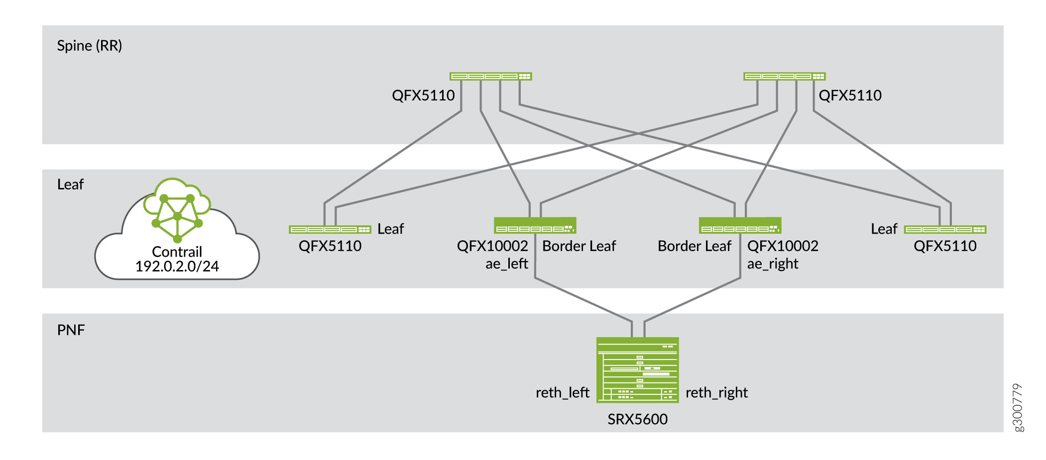
Figure 1 shows an example topology of how a PNF device (SRX5600) is used to allow inter-LR traffic to pass through a service chain. You can use the SRX device as a layer 3 PNF device after you have configured the device during device onboarding. The PNF device is connected to border leaf or spine devices.
Getting Started
The general workflow to create a PNF service chain is as follows:

These topics provide instructions to create a PNF service chain.
Onboard Fabric Devices
Follow the steps provided in the Onboard Brownfield Devices topic to onboard brownfield fabric devices and assign roles to the devices.
While onboarding devices, ensure that you enter the IP subnet in the PNF Servicechain subnets field to establish EBGP session between PNF device and Spine switch.
See Table 1 for an example configuration of a centrally-routed bridging (CRB) architecture that includes PNF functionality. The SRX device uses the physical role, pnf, and routing-bridging role, PNF-Servicechain. The border leaf device uses PNF-Servicechain routing-bridging role.
|
Device |
Physical Role |
Routing-Bridging Role |
|---|---|---|
|
Spine devices |
spine |
CRB-Gateway, Route-Reflector, CRB-MCAST-Gateway |
|
Border leaf |
leaf |
PNF-Servicechain |
|
Leaf devices |
leaf |
CRB-Access |
|
SRX Device |
pnf |
PNF-Servicechain |
Configure Virtual Networks
Follow the steps provided in the Create Virtual Network topic to create virtual networks.
After you have created the virtual networks, you create a network policy. For more information on creating a network policy and attaching the network policy to the virtual network, see Create Network Policy.
Configure Virtual Port Groups
Follow the steps provided in the Configuring Virtual Port Groups topic to configure virtual port groups. A virtual port group defines leaf device interfaces attached to end hosts
Ensure that you assign the virtual port group to the virtual network that you created.
For example, when you create two virtual networks, VN-A and VN-B, you will have to create one virtual port group for VN-A and another for VN-B.
Configure Logical Routers
Follow the steps provided in the Create Logical Routers topic to configure logical routers.
While creating logical router, ensure that you
-
Select VXLAN Routing as the Logical Router Type.
-
Select the virtual network(s) from the Connected Networks list.
-
Select the physical routers (the spine devices) to which you want to extend the logical router.
Configure PNF
Configuring PNF includes the following:
-
Creating a PNF Service Template to define the physical connectivity of the PNF to the fabric.
-
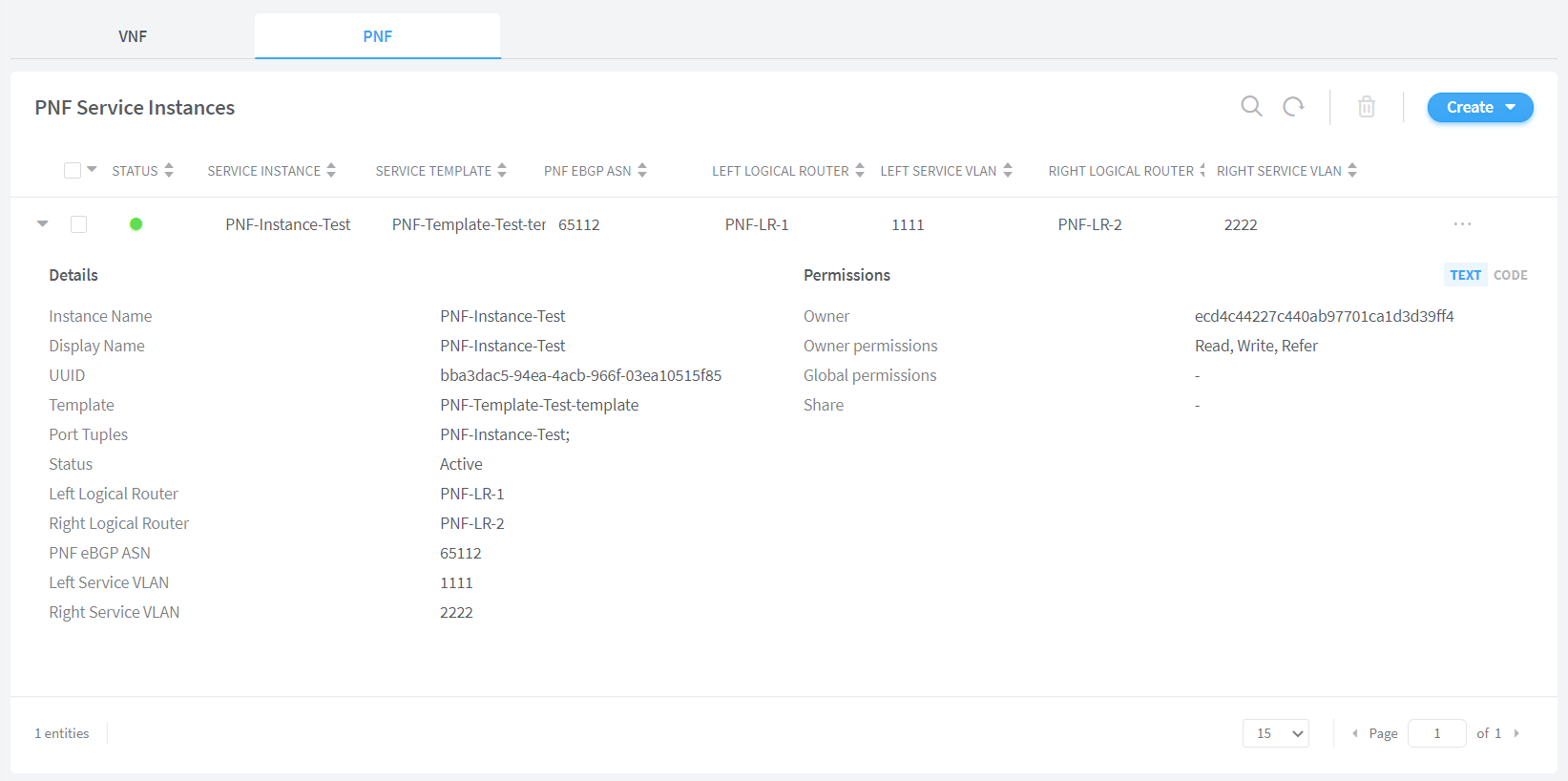
Creating a PNF Service Instance to define the interconnection of the two logical routers.
Follow these steps to create PNF service template and PNF service instance by using the Contrail Command UI.
View Service Appliance Sets and Service Appliances
(Optional) Follow these steps to view Service Appliance Sets and Service Appliances by using the Contrail Command UI:
Alternatively, you can also navigate to the Monitoring>Operations page to verify the status of the job.

