Configure Authentication Methods for SRX Firewall Users
Learn how to configure pass-through and captive portal authentication.
Example: Configure Pass-Through Authentication
This example shows how to configure pass-through authentication to authenticate firewall users. A firewall user is a network user who must provide a username and password when initiating a connection across the firewall.
Pass-through authentication allows SRX Series administrators to restrict users who attempt to access a resource in another zone using FTP, Telnet, HTTP, or HTTPS. If the traffic matches a security policy whose action is pass-through authentication, the user is required to provide login information.
For HTTPS, to ensure security the HTTPS default certificate key size is 2048 bits. If you do not specify a certificate size, the default size is assumed.
Requirements
Before you begin, define firewall users. See Firewall User Authentication Overview.
This example uses the following hardware and software components:
SRX Series Firewall
Firewall user’s system
Packet destination system
Overview
The pass-through authentication process is triggered when a client, referred to as a firewall user, attempts to initiate an FTP, a Telnet, or an HTTP session to access a resource in another zone. The SRX Series firewall acts as a proxy for an FTP, a Telnet, an HTTP, or an HTTPS server so that it can authenticate the firewall user before allowing the user access to the actual FTP, Telnet, or HTTP server behind the firewall.
If traffic generated from a connection request sent by a firewall user matches a security policy rule bidirectionally and that rule specifies pass-through firewall authentication as the action of its then clause, the SRX Series Firewall requires the firewall user to authenticate to a Junos OS proxy server.
If the authentication is successful, subsequent traffic from the same source IP address is automatically allowed to pass through the SRX Series Firewall if the traffic matches the security policy tuples.
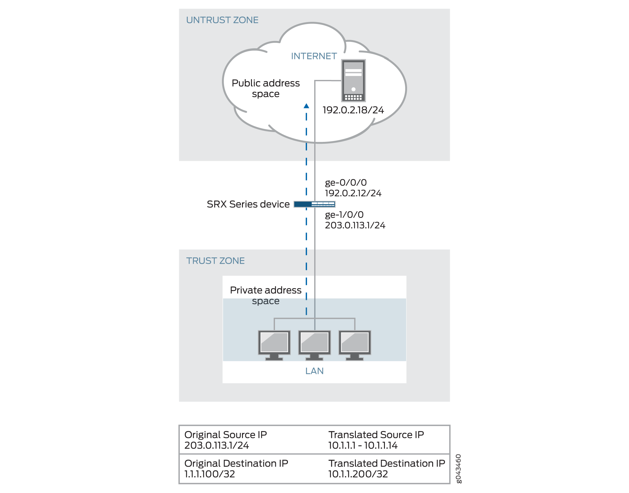
Figure 1 shows the topology used in this example.
Although the topology shows use of an external server, it is not covered in the configuration. It is outside the scope of this example.
Configuration
Procedure
CLI Quick Configuration
To quickly configure this example, copy the following commands to a text file, remove any line breaks, change any details necessary to match your network configuration, copy and paste the commands into the CLI at the [edit] hierarchy level, and then enter commit from configuration mode.
set interfaces ge-0/0/1 unit 0 family inet address 203.0.113.35/24
set interfaces ge-5/0/0 unit 0 family inet address 192.0.2.1/24
set access profile FWAUTH client FWClient1 firewall-user password password
set access firewall-authentication pass-through default-profile FWAUTH
set access firewall-authentication pass-through telnet banner success "WELCOME TO JUNIPER TELNET SESSION"
set security zones security-zone UT-ZONE host-inbound-traffic system-services all
set security zones security-zone UT-ZONE interfaces ge-0/0/1.0 host-inbound-traffic protocols all
set security zones security-zone T-ZONE host-inbound-traffic system-services all
set security zones security-zone T-ZONE interfaces ge-5/0/0.0 host-inbound-traffic protocols all
set security policies from-zone UT-ZONE to-zone T-ZONE policy P1 match source-address any
set security policies from-zone UT-ZONE to-zone T-ZONE policy P1 match destination-address any
set security policies from-zone UT-ZONE to-zone T-ZONE policy P1 match application junos-telnet
set security policies from-zone UT-ZONE to-zone T-ZONE policy P1 then permit firewall-authentication pass-through client-match FWClient1
Step-by-Step Procedure
The following example requires you to navigate various levels in the configuration hierarchy. For instructions on how to do that, see Using the CLI Editor in Configuration Mode.
To configure pass-through authentication:
Configure two interfaces and assign IP addresses to them.
Note:For this example, it is optional to assign two addresses to the interfaces.
[edit]
user@host# set interfaces ge-0/0/1 unit 0 family inet address 203.0.113.35/24
user@host# set interfaces ge-5/0/0 unit 0 family inet address 192.0.2.1/24
Create the FWAUTH access profile for the FWClient1 user, specify the user’s password, and define a success banner for Telnet sessions.
[edit access]
user@host# set access profile FWAUTH client FWClient1 firewall-user password pwd
user@host# set firewall-authentication pass-through default-profile FWAUTH
user@host# set firewall-authentication pass-through telnet banner success "WELCOME TO JUNIPER TELNET SESSION"
Configure security zones.
Note:For this example, it is optional to configure a second interface for a security zone.
[edit security zones]
user@host# set security-zone UT-ZONE host-inbound-traffic system-services all
user@host# set security-zone UT-ZONE interfaces ge-0/0/1.0 host-inbound-traffic protocols all
user@host# set security-zone T-ZONE host-inbound-traffic system-services all
user@host# set security-zone T-ZONE interfaces ge-5/0/0.0 host-inbound-traffic protocols all
Assign security policy P1 to the security zones.
[edit security policies]
user@host# set from-zone UT-ZONE to-zone T-ZONE policy P1 match source-address any
user@host# set from-zone UT-ZONE to-zone T-ZONE policy P1 match destination-address any
user@host# set from-zone UT-ZONE to-zone T-ZONE policy P1 match application junos-telnet
user@host# set from-zone UT-ZONE to-zone T-ZONE policy P1 then permit firewall-authentication pass-through client-match FWClient1
Use Telnet to authenticate the FWClient1 firewall user to host2.
user@FWClient1# run telnet 192.0.2.1/24
Trying 192.0.2.1/24...
Connected to 192.0.2.1/24
Escape character is '^]'.
Firewall User Authentication
Username: FWClient1
Password:$ABC123
          WELCOME TO JUNIPER TELNET SESSION
Host1 (ttyp0)
login: user
Password: $ABC123
--- JUNOS 10.1R1.1 built 2009-10-12 13:30:18 UTC
%
Results
From configuration mode, confirm your configuration by entering these commands.
show interfacesshow accessshow security zonesshow security policies
If the output does not display the intended configuration, repeat the configuration instructions in this example to correct it.
For brevity, the output includes only the configuration that is relevant to this example. Any other configuration on the system has been replaced with ellipses (...).
user@host# show interfaces
    ge-0/0/1 {
        unit 0 {
            family inet {
                address 203.0.113.35;
            }
        }
    }
    ge-5/0/0 {
        unit 0 {
            family inet {
                address 192.0.2.1/24;
            }
        }
    }
...
user@host# show access
    profile FWAUTH {
        authentication-order password;
        client FWClient1 {
            firewall-user {
                password "$ABC123"; ## SECRET-DATA
            }
        }
    }
    firewall-authentication {
        pass-through {
            default-profile FWAUTH;
            telnet {
                banner {
                    success "WELCOME TO JUNIPER TELNET SESSION";
                }
            }
        }
    }
user@host# show security zones
    security-zone UT-ZONE {
        host-inbound-traffic {
            system-services {
                all;
            }
        }
            interfaces {
                ge-0/0/1.0 {
                    host-inbound-traffic {
                        protocols {
                            all;
                        }
                    }
                }
            }
            security-zone T-ZONE {
                host-inbound-traffic {
                    system-services {
                        all;
                    }
                }
                interfaces {
                    ge-5/0/0.0 {
                        host-inbound-traffic {
                            protocols {
                                all;
                            }
                        }
                    }
                }
            }
user@host# show security policies
...
from-zone UT-ZONE to-zone T-ZONE {
    policy P1 {
        match {
            source-address any;
            destination-address any;
            application junos-telnet;
        }
        then {
            permit {
                firewall-authentication {
                    pass-through {
                        client-match FWClient1;
                    }
                }
            }
        }
    }
}
If you are done configuring the device, enter commit from configuration mode.
Verification
To confirm that the configuration is working properly, perform this task:
Verifying Firewall User Authentication and Monitoring Users and IP Addresses in the Authentication Table
Purpose
Display firewall authentication user history and verify the number of firewall users who successfully authenticated and the number of firewall users who failed to log in.
Action
From operational mode, enter these show commands:
user@host> show security firewall-authentication history
History of firewall authentication data:
Authentications: 2
Id Source Ip Date Time Duration Status User
1 203.0.113.12 2010-10-12 21:24:02 0:00:24 Failed FWClient1
2 203.0.113.12 2010-10-12 21:24:48 0:00:22 Success FWClient1
user@host> show security firewall-authentication history identifier 1
Username: FWClient1
Source IP: 203.0.113.12
Authentication state: Success
Authentication method: Pass-through using Telnet
Access start date: 2010-10-12
Access start time: 21:24:02
Duration of user access: 0:00:24
Source zone: UT-ZONE
Destination zone: T-ZONE
Access profile: FWAUTH
Bytes sent by this user: 0
Bytes received by this user: 2660
user@host> show security firewall-authentication users
Firewall authentication data:
Total users in table: 1
Id Source Ip Src zone Dst zone Profile Age Status User
4 203.0.113.12     UT-ZONE  T-ZONE   FWAUTH     1 Success   FWClient1
user@host> show security firewall-authentication users identifier 3
Username: FWClient1
Source IP: 203.0.113.12
Authentication state: Success
Authentication method: Pass-through using Telnet
Age: 3
Access time remaining: 9
Source zone: UT-ZONE
Destination zone: T-ZONE
Access profile: FWAUTH
Interface Name: ge-0/0/1.0
Bytes sent by this user: 0
Bytes received by this user: 1521
Example: Configure HTTPS Traffic to Trigger Pass-Through Authentication
This example shows how to configure HTTPS traffic to trigger pass-through authentication. HTTPS is more secure than HTTP, so it has become more popular and is more widely used.
Requirements
This example uses the following hardware and software components:
SRX Series Firewall
Two PCs running Linux and Open SSL. One PC acts as a client and another as an HTTPS server. The two PCs are used to create key files and to send traffic.
Junos OS Release 12.1X44-D10 or later for SRX5400, SRX5600, and SRX5800 Firewalls and Junos OS Release 15.1X49-D40 or later for vSRX Virtual Firewall, SRX300, SRX320, SRX340, SRX345, SRX380, SRX550M, and SRX1500 Firewalls.
Starting in Junos OS Release 12.1X44-D10 and Junos OS Release 17.3R1, HTTPS-based authentication is introduced on SRX5400, SRX5600, and SRX5800 Firewalls.
Starting in Junos OS Release 15.1X49-D40 and Junos OS Release 17.3R1, HTTPS-based authentication is introduced on vSRX Virtual Firewall, SRX300, SRX320, SRX340, SRX345, SRX380, SRX550M, and SRX1500 Firewalls.
Before you begin:
An SRX Series Firewall has to decode HTTPS traffic to trigger pass-through authentication. Then, SSL termination proxy creates and installs a private key file and a certification file. The following list describes the steps to create and install a private key file and a certification key file.
If you have an official .crt file and .key file, then you can directly upload and install the files on the SRX Series Firewall. If you do not have a .crt file and .key file, follow the procedure to create and install the files. Instructions specified in Step 1 and Step 2 must be run on a PC with Linux and OpenSSL installed. Instructions specified in Step 3 and Step 4 must be run in operational mode.
To create and install a private key file and a certification file:
On a PC create the .key file.
openssl genrsa -out /tmp/server.key 1024
On a PC, create the .crt file.
openssl req -new -x509 -days 365 -key /tmp/server.key -out /tmp/device.crt -subj "/C=CN/ST=BJ/L=BJ/O=JNPR/OU=CNRD/CN=203.0.113.11/emailAddress=device@mycompany.com"
-
Upload the .key and .crt files to an SRX Series Firewall, and install the files on the device using the following command from operational mode:
user@host> request security pki local-certificate load filename /var/tmp/device.crt key /var/tmp/device.key certificate-id device
Overview
Firewall authentication initiates a secure connection to be established across two devices. A network user must provide a username and password for authentication when initiating a connection across the firewall. Firewall authentication supports HTTPS traffic for pass-through authentication. HTTPS can secure HTTP firewall authentication traffic between users and the SRX Series Firewall.
HTTPS is the secure version of HTTP, the protocol over which data is sent between the user and the device that the user is connected to. All communications between the user and the connected devices are encrypted. HTTPS is often used to protect highly confidential online transactions like online banking and online shopping order forms.
In this example, HTTPS traffic is used to trigger pass-through authentication because HTTPS is more secure than HTTP. For HTTPS traffic to trigger pass-through authentication you must first configure the SSL termination profile.
Figure 2 shows an example of pass-through authentication using HTTPS traffic. In this example, a host or a user from an untrust zone tries to access resources on the trust zone. The SRX Series Firewall uses HTTPS to collect the username and password information. Subsequent traffic from the host or user is allowed or denied based on the result of this authentication.
Configuration
CLI Quick Configuration
To quickly configure this example, copy the following commands to a text file, remove any line breaks, change any details necessary to match your network configuration, copy and paste the commands into the CLI at the [edit] hierarchy level, and then enter commit from configuration mode.
set interfaces ge-0/0/0 unit 0 family inet address 192.0.2.12/24
set interfaces ge-1/0/0 unit 0 family inet address 203.0.113.1/24
set security policies from-zone trust to-zone untrust policy p1 match source-address any
set security policies from-zone trust to-zone untrust policy p1 match destination-address any
set security policies from-zone trust to-zone untrust policy p1 match application any
set security policies from-zone trust to-zone untrust policy p1 then permit firewall-authentication pass-through access-profile local_pf
set security policies from-zone trust to-zone untrust policy p1 then permit firewall-authentication pass-through ssl-termination-profile ssl_pf
set security policies from-zone trust to-zone untrust policy p1 then log session-init
set security policies from-zone trust to-zone untrust policy p1 then log session-close
set security zones security-zone trust interfaces ge-0/0/0.0 host-inbound-traffic system-services all
set security zones security-zone trust interfaces ge-0/0/0.0 host-inbound-traffic protocols all
set security zones security-zone untrust interfaces ge-1/0/0.0 host-inbound-traffic system-services all
set security zones security-zone untrust interfaces ge-1/0/0.0 host-inbound-traffic protocols all
set access profile local_pf client user1 firewall-user password <password>
set access firewall-authentication pass-through default-profile local_pf
set services ssl termination profile ssl_pf server-certificate device
Procedure
Step-by-Step Procedure
To configure HTTPS traffic to trigger pass-through authentication:
Configure interfaces and assign IP addresses.
[edit interfaces]
user@host# set ge-0/0/0 unit 0 family inet address 192.0.2.12/24
user@host# set ge-1/0/0 unit 0 family inet address 203.0.113.1/24
Configure security policies to permit firewall authenticated traffic from zone trust to zone untrust.
[edit security policies]
user@host# set from-zone trust to-zone untrust policy p1 then permit firewall-authentication pass-through access-profile local_pf
user@host# set from-zone trust to-zone untrust policy p1 then permit firewall-authentication pass-through ssl-termination-profile ssl_pf
Specify a policy action to take when a packet matches the criteria.
[edit security policies]
user@host# set from-zone trust to-zone untrust policy p1 match source-address any
user@host# set from-zone trust to-zone untrust policy p1 match destination-address any
user@host# set from-zone trust to-zone untrust policy p1 match application any
user@host# set from-zone trust to-zone untrust policy p1 then log session-init
user@host# set from-zone trust to-zone untrust policy p1 then log session-close
Configure security zones and assign interfaces.
[edit security zones]
user@host#  set security-zone trust interfaces ge-0/0/0.0 host-inbound-traffic protocols all
user@host# set security-zone trust interfaces ge-0/0/0.0 host-inbound-traffic system-services all
Configure application services for zones.
[edit security zones]
user@host# set security-zone trust host-inbound-traffic system-services all protocols all
user@host# set security-zone untrust host-inbound-traffic system-services all protocols all
Create an access profile and configure the client as a firewall user and set the password.
[edit access]
user@host# set profile local_pf client user1 firewall-user password <password>
Configure the type of firewall and the default profile name where the authentication settings are defined.
[edit access]
user@host# set firewall-authentication pass-through default-profile local_pf
Configure the SSL termination profile and enter a local certificate identifier name.
[edit services]
user@host# set ssl termination profile ssl_pf server-certificate device
Results
From configuration mode, confirm your configuration
by entering the show interfaces, show security policies, show security zones, show access, and show services ssl termination commands. If the output does
not display the intended configuration, repeat the configuration instructions
in this example to correct it.
user@host# show interfaces
...
interfaces
    ge-0/0/0 {
        unit 0 {
            family inet {
                address 192.0.2.12;
            }
        }
    }
    ge-1/0/0 {
        unit 0 {
            family inet {
                address 203.0.113.1/24;
            }
        }
    }
user@host# show security policies
...
policies
    from-zone trust to-zone untrust {
        policy p1 {
            match {
                source-address any;
                destination-address any;
                application any;
            }
            then {
                permit {
                    firewall-authentication {
                        pass-through {
                            access-profile local_pf;
                            ssl-termination-profile ssl_pf;
                        }
                    }
                }
                log {
                    session-init;
                    session-close;
                }
            }
        }
    }
}
user@host# show security zones
...
zones {
    security-zone trust {
        interfaces {
            ge-0/0/0.0 {
                host-inbound-traffic {
                    system-services {
                        all;
                    }
                    protocols {
                        all;
                    }
                }
            }
        }
    }
    security-zone untrust {
        interfaces {
            ge-1/0/0.0 {
                host-inbound-traffic {
                    system-services {
                        all;
                    }
                    protocols {
                        all;
                    }
                }
            }
        }
    }
user@host# show access
...
access {
    profile local_pf {
        client user1 {
            firewall-user {
                password password;
            }
        }
    }
    firewall-authentication {
        pass-through {
            default-profile local_pf;
        }
    }
user@host# show services ssl termination
...
services {
    ssl {
        termination {
            profile ssl_pf {
                server-certificate device;
            }
        }
    }
}
If you are done configuring the device, enter commit from configuration mode.
Verification
Verifying the Configuration
Purpose
Verify that the configuration is correct.
Action
From operational mode, enter the show security
firewall-authentication users command for identifier 1.
user@host> show security firewall-authentication users identifier 1
    Username: user1
    Source IP: 203.0.113.1/24
    Authentication state: Success
    Authentication method: Pass-through using HTTPS
    Age: 0
    Access time remaining: 10
    Lsys: root-logical-system
    Source zone: trust
    Destination zone: untrust
    Access profile: local_pf
    Interface Name: ge-0/0/0.0
    Bytes sent by this user: 946
    Bytes received by this user: 0
Meaning
The show security firewall-authentication users command displays the firewall authentication user information for
the specified identifier. If the output displays Pass-through using
HTTPS in the Authentication method field and Success in the Authentication
state field, then your configuration is correct.
Example: Configure Captive Portal Authentication
This example shows how to enable Captive Portal authentication and set up a policy that allows access to a user when traffic encounters a policy that has Captive Portal authentication enabled.
Requirements
Before you begin:
Define firewall users. See Firewall User Authentication Overview.
Add the Web authentication HTTP flag under the interface’s address hierarchy to enable Web authentication.
Overview
To enable Web authentication, you must specify the IP address of the device hosting the HTTP session. These settings are used if the firewall user accessing a protected resource wants to be authenticated by directly accessing the webserver or by Web authentication. The following instructions show how to set up a policy that allows access to the FWClient1 user when traffic encounters a policy that has Web authentication enabled (Policy-W). (See Figure 3.) In this example, FWClient1 has already authenticated through the Web authentication login page.
The FWClient1 firewall user does the following to get authenticated:
Points the browser to the Web authentication IP (198.51.100.63/24) to get authenticated first
Starts traffic to access resources specified by the policy-W policy
When you configure the device as described in these instructions and the user successfully authenticates, the screen illustrated in Figure 4 appears.

Configuration
Procedure
CLI Quick Configuration
To quickly configure this example, copy the following commands to a text file, remove any line breaks, change any details necessary to match your network configuration, copy and paste the commands into the CLI at the [edit] hierarchy level, and then enter commit from configuration mode.
set interfaces ge-0/0/1 unit 0 family inet address 198.51.100.23/24set interfaces ge-0/0/1 unit 0 family inet address 198.51.100.63/24 web-authentication httpset interfaces fe-5/0/0 unit 0 family inet address 203.0.113.15/24set access profile WEBAUTH client FWClient1 firewall-user password pwdset access firewall-authentication web-authentication default-profile WEBAUTHset access firewall-authentication web-authentication banner success "WEB AUTH LOGIN SUCCESS"set security zones security-zone UT-ZONE host-inbound-traffic system-services allset security zones security-zone UT-ZONE interfaces ge-0/0/1.0 host-inbound-traffic protocols allset security zones security-zone T-ZONE host-inbound-traffic system-services allset security zones security-zone T-ZONE interfaces ge-5/0/0.0 host-inbound-traffic protocols allset security policies from-zone UT-ZONE to-zone T-ZONE policy P1 match source-address anyset security policies from-zone UT-ZONE to-zone T-ZONE policy P1 match destination-address anyset security policies from-zone UT-ZONE to-zone T-ZONE policy P1 match application anyset security policies from-zone UT-ZONE to-zone T-ZONE policy P1 then permit firewall-authentication web-authentication client-match FWClient1set system services web-management http interface ge-0/0/1.0
Step-by-Step Procedure
The following example requires you to navigate various levels in the configuration hierarchy. For instructions on how to do that, see Using the CLI Editor in Configuration Mode.
To configure Web authentication:
Configure two interfaces and assign IP addresses to them.
Note:For this example, it is optional to assign two addresses to the interfaces.
[edit]
user@host# set interfaces ge-0/0/1 unit 0 family inet address 198.51.100.23/24
user@host# set interfaces ge-0/0/1 unit 0 family inet address 198.51.100.63/24 web-authentication http
user@host# set interfaces fe-5/0/0 unit 0 family inet address 203.0.113.15/24
Create the WEBAUTH access profile for the FWClient1 user, specify the user’s password, and define a success banner.
[edit access]
user@host# set profile WEBAUTH client FWClient1 firewall-user password pwd
user@host# set firewall-authentication web-authentication default-profile WEBAUTH
user@host# set firewall-authentication web-authentication banner success "WEB AUTH LOGIN SUCCESS"
Configure security zones.
Note:For this example, it is optional to configure a second interface for a security zone.
[edit security zones]
user@host# set security-zone UT-ZONE host-inbound-traffic system-services all
user@host# set security-zone UT-ZONE interfaces ge-0/0/1.0 host-inbound-traffic protocols all
user@host# set security-zone T-ZONE host-inbound-traffic system-services all
user@host# set security-zone T-ZONE interfaces ge-5/0/0.0 host-inbound-traffic protocols all
Assign security policy P1 to the security zones.
[edit security policies]
user@host# set from-zone UT-ZONE to-zone T-ZONE policy P1 match source-address any
user@host# set from-zone UT-ZONE to-zone T-ZONE policy P1 match destination-address any
user@host# set from-zone UT-ZONE to-zone T-ZONE policy P1 match application any
user@host# set from-zone UT-ZONE to-zone T-ZONE policy P1 then permit firewall-authentication web-authentication client-match FWClient1
Activate the HTTP process (daemon) on your device.
[edit]
user@host# set system services web-management http interface ge-0/0/1.0
Results
From configuration mode, confirm your configuration by entering these commands:
show interfacesshow accessshow security zonesshow security policiesshow system services
If the output does not display the intended configuration, repeat the configuration instructions in this example to correct it.
For brevity, this show output includes only the
configuration that is relevant to this example. Any other configuration
on the system has been replaced with ellipses (...).
user@host# show interfaces
...
}
ge-0/0/1{
    unit 0 {
        family inet {
            address 198.51.100.23/24 {
            address 198.51.100.63/24 {
                web-authentication http;
            }
        }
    }
}
fe-5/0/0 {
    unit 0 {
        family inet {
            address 198.51.100.14/24;
        }
    }
}
...


user@host# show access
profile WEBAUTH {
    client FWClient1 {
        firewall-user {
            password "$ABC123"; ## SECRET-DATA
        }
    }
}
firewall-authentication {
    web-authentication {
        default-profile WEBAUTH;
        banner {
            success "WEB AUTH LOGIN SUCCESS";
        }
    }
}


user@host# show security zones
...
}
security-zone UT-ZONE {
    host-inbound-traffic {
       system-services {
            all;
        }
    }
    interfaces {
        ge-0/0/1.0 {
            host-inbound-traffic {
                protocols {
                    all;
                }
            }
        }
    }
}
security-zone T-ZONE {
    host-inbound-traffic {
       system-services {
            all;
        }
    }
    interfaces {
        ge-5/0/0.0 {
            host-inbound-traffic {
                protocols {
                    all;
                }
            }
        }
    }
}


user@host# show security policies
...
from-zone UT-ZONE to-zone T-ZONE {
    policy P1 {
       match {
            source-address any;
            destination-address any;
            application any;
       }
       then {
            permit {
                firewall-authentication {
                    web-authentication {
                        client-match FWClient1;
                    }
                }
            }
       }
    }
}

user@host# show system services
...
ftp;
ssh;
telnet;
web-management {
    http {
        interface g-0/0/1.0;
    }
}
If you are done configuring the device, enter commit from configuration mode.
Verification
To confirm that the configuration is working properly, perform this task:
Verifying Firewall User Authentication and Monitoring Users and IP Addresses in the Authentication Table
Purpose
Display firewall authentication user history and verify the number of firewall users who successfully authenticated and firewall users who failed to log in.
Action
From operational mode, enter these show commands:
user@host> show security firewall-authentication history
user@host> show security firewall-authentication history identifier 1
user@host> show security firewall-authentication users
user@host> show security firewall-authentication users identifier 3
user@host> show security firewall-authentication history
History of firewall authentication data:
Authentications: 1
Id Source Ip Date Time Duration Status User
5 198.51.100.75      2010-04-24 01:08:57 0:10:30    Success  FWClient1
user@host> show security firewall-authentication history identifier 1
Username: FWClient1
Source IP: 198.51.100.752
Authentication state: Success
Authentication method: Web-authentication
Access start date: 2010-10-12
Access start time: 21:24:02
Duration of user access: 0:00:24
Source zone: N/A
Destination zone: N/A
Access profile: WEBAUTH
Bytes sent by this user: 0
Bytes received by this user: 2660
user@host> show security firewall-authentication users
Firewall authentication data:
Total users in table: 1
Id Source Ip Src zone Dst zone Profile Age Status User
4 198.51.100.75     N/A  N/A   WEBAUTH     1 Success   FWClient1
user@host> show security firewall-authentication users identifier 3
Username: FWClient1
Source IP: 198.51.100.75
Authentication state: Success
Authentication method: Web-authentication
Age: 3
Access time remaining: 9
Source zone: N/A
Destination zone: N/A
Access profile: WEBAUTH
Interface Name: ge-0/0/1.0
Bytes sent by this user: 0
Bytes received by this user: 1521
Example: Configure HTTPS Traffic to Trigger Captive Portal Authentication
This example shows how to configure HTTPS traffic to trigger Captive Portal authentication. HTTPS is widely used for Captive Portal authentication because it is more secure than HTTP.
Requirements
Before you begin:
This example uses the following hardware and software components:
SRX Series Firewall
Two PCs with Linux and Open SSL installed. One PC acts as a client and another as an HTTPS server. The two PCs are used to create key files and to send traffic.
Junos OS Release 12.1X44-D10 or later for SRX5400, SRX5600, and SRX5800 devices and Junos OS Release 15.1X49-D40 or later for vSRX Virtual Firewall, SRX300, SRX320, SRX340, SRX345, SRX380, SRX550M, and SRX1500 Services Gateways.
An SRX Series Firewall has to decode the HTTPS traffic to trigger Web authentication. The following list describes the steps to create and install a private key file and a certification key file.
If you have an official .crt file and .key file, then you can
directly upload and install the files on the SRX Series Firewall. If you do not
have a .crt file and .key file, then follow
the procedure to create and install the files. Instructions specified in Step 1
and Step 2 must be run on a PC which has Linux and OpenSSL installed.
Instructions specified in Step 3 and Step 4 must be run in operational mode.
From the PC, create the
.keyfile.openssl genrsa -out /tmp/server.key 1024
From the PC, create the
.crtfile.openssl req -new -x509 -days 365 -key /tmp/server.key -out /tmp/device.crt -subj "/C=CN/ST=BJ/L=BJ/O=JNPR/OU=CNRD/CN=203.0.113.22/emailAddress=device@mycomany.com"
-
From the SRX Series Firewall, upload the
.keyand.crtfiles and install the files on the device using the following command:user@host> request security pki local-certificate load filename /var/tmp/device.crt key /var/tmp/device.key certificate-id device
Overview
Firewall authentication initiates a secure connection to be established across two devices. A network user must provide a username and password for authentication when initiating a connection across the firewall. Firewall authentication supports HTTPS traffic for pass-through authentication. HTTPS can secure HTTP firewall authentication traffic between users and the SRX Series Firewall.
HTTPS is the secure version of HTTP, the protocol over which data is sent between the user and the device that the user is connected to. All communications between the user and the connected devices are encrypted. HTTPS is often used to protect highly confidential online transactions like online banking and online shopping order forms.
In this example, HTTPS traffic is used to trigger Web authentication because HTTPS is more secure than HTTP.
The user uses HTTPS to access an IP address on the device that is enabled for Web authentication. In this scenario, the user does not use HTTPS to access the IP address of the protected resource. The user is prompted for a username and password, which are verified by the device. Subsequent traffic from the user or host to the protected resource is allowed or denied based on the results of this Web authentication.
If you enable web-authentication https on an interface, you must
configure web-management https to prevent the device from
generating a commit error.
Figure 5 shows an example of Web authentication using HTTPS traffic.
Configuration
CLI Quick Configuration
To quickly configure this example, copy the following commands to a text file, remove any line breaks, change any details necessary to match your network configuration, copy and paste the commands into the CLI at the [edit] hierarchy level, and then enter commit from configuration mode.
set system services web-management https pki-local-certificate device
set interfaces ge-0/0/0 unit 0 family inet address 203.0.113.18/24
set interfaces ge-0/0/0 unit 0 family inet address 203.0.113.115/24  web-authentication https
set interfaces ge-0/0/1 unit 0 family inet address 192.0.2.5/24
set security policies from-zone trust to-zone untrust policy p1 match source-address any
set security policies from-zone trust to-zone untrust policy p1 match destination-address any
set security policies from-zone trust to-zone untrust policy p1 match application any
 set security policies from-zone trust to-zone untrust policy p1 then permit
set access profile local_pf client user1 firewall-user password user1
set access firewall-authentication web-authentication default-profile local_pf
set security policies from-zone trust to-zone untrust policy p1 then permit firewall-authentication web-authentication
Procedure
Step-by-Step Procedure
To configure HTTPS traffic to trigger Web authentication:
Enable Web-management support to HTTPS traffic.
[edit system services]
user@host# set web-management https pki-local-certificate device
Configure interfaces and assign IP addresses. Enable Web authentication at ge-0/0/0 interface.
[edit interfaces]
user@host# set ge-0/0/0 unit 0 family inet address 203.0.113.18/24
set ge-0/0/0 unit 0 family inet address 203.0.113.115/24 web-authentication https
user@host# set ge-0/0/1 unit 0 family inet address 192.0.2.5/24
Configure security policies to permit firewall authenticated traffic from zone trust to zone untrust.
[edit security policies]
user@host# set from-zone trust to-zone untrust policy p1 match source-address any destination-address any  application any
user@host# set security policies from-zone trust to-zone untrust policy p1 then permit
Create an access profile, configure the client as a firewall user, and set the password.
[edit access]
user@host# set profile local_pf client user1 firewall-user password user1
Configure the type of firewall authentication settings.
[edit access]
user@host# set firewall-authentication web-authentication default-profile local_pf
Specify a policy action to take when a packet matches the criteria.
[edit security policies]
user@host# set from-zone trust to-zone untrust policy p1 then permit firewall-authentication web-authentication
Results
From configuration mode, confirm your configuration
by entering the show system services, show interfaces, show security policies, and show access commands.
If the output does not display the intended configuration, repeat
the configuration instructions in this example to correct it.
user@host#  show system services
    web-management {
        https {
            pki-local-certificate device;
        }
}
user@host#  show interfaces
    ge-0/0/0 {
    unit 0 {
        family inet {
            address 203.0.113.115/24  {
                web-authentication https;
            }
        }
}
    ge-0/0/1 {
        unit 0 {
            family inet {
                address 192.0.2.5/24;
            }
        }
    }
user@host# show security policies
from-zone trust to-zone untrust {
    policy p1 {
        match {
            source-address any;
            destination-address any;
            application any;
        }
        then {
            permit {
                firewall-authentication {
                    web-authentication;
                }
            }
        }
    }
}
user@host# show access
    profile local_pf {
        client user1 {
            firewall-user {
                password "user1";
            }
        }
    }
        firewall-authentication {
            web-authentication {
                default-profile local_pf;
            }
If you are done configuring the device, enter commit from configuration mode.
Verification
Verifying the Configuration
Purpose
Verify that the configuration is correct.
Action
From operational mode, enter the show security
firewall-authentication users identifier identifier command.
Sample Output
user@host> show security firewall-authentication users identifier 1
    Username: user1
    Source IP: 203.1.113.102
    Authentication state: Success
    Authentication method: Web-authentication
    Age: 0
    Access time remaining: 10
    Lsys: root-logical-system
    Source zone: N/A
    Destination zone: N/A
    Access profile: local_pf
    Bytes sent by this user: 0
    Bytes received by this user: 0
Meaning
The show security firewall-authentication users
identifier identifier command displays
the firewall authentication user information using the identifier
ID of the user. If the authentication method parameter displays Web
authentication and the authentication state parameter displays success
in your output then your configuration is correct.
Configure Captive Portal for Unauthenticated Browsers
Learn how to configure captive portal for unauthenticated browsers.
Here are some examples of how you can configure security policies to use the auth-only-browser and auth-user-agent firewall authentication features.
For Pass-Through Authentication
Configures a security policy for pass-through authentication that uses the auth-only-browser parameter.
user@host# set security policies from-zone trust to-zone untrust policy p1 match source-address any
user@host# set security policies from-zone trust to-zone untrust policy p1 match destination-address any
user@host# set security policies from-zone trust to-zone untrust policy p1 match application any
user@host# set security policies from-zone trust to-zone untrust policy p1 then permit firewall-authentication pass-through auth-only-browser access-profile my-access-profile1t
Configures a security policy for pass-through authentication that uses the auth-user-agent parameter without auth-only-browser.
user@host# set security policies from-zone trust to-zone untrust policy p2 match source-address any
user@host# set security policies from-zone trust to-zone untrust policy p2 match destination-address any
user@host# set security policies from-zone trust to-zone untrust policy p2 match application any
user@host# set security policies from-zone trust to-zone untrust policy p2 then permit firewall-authentication pass-through auth-user-agent  Opera1 access-profile my-access-profile2
Configures a security policy for pass-through authentication that uses the auth-only-browser with the auth-user-agent parameter.
user@host# set security policies from-zone trust to-zone untrust policy p3 match source-address any
user@host# set security policies from-zone trust to-zone untrust policy p3 match destination-address any
user@host# set security policies from-zone trust to-zone untrust policy p3 match application any
user@host# set security policies from-zone trust to-zone untrust policy p3 then permit firewall-authentication pass-through auth-only-browser  auth-user-agent  Opera1 my-access-profile3
For User Firewall Authentication
Configures a security policy for user-firewall authentication that uses the auth-only-browser parameter.
user@host# set security policies from-zone trust to-zone untrust policy p4 match source-address any
user@host# set security policies from-zone trust to-zone untrust policy p4 match destination-address any
user@host# set security policies from-zone trust to-zone untrust policy p4 match application any
user@host# set security policies from-zone trust to-zone untrust policy p4 then permit firewall-authentication user-firewall auth-only-browser access-profile my-access-profile4t
Configures a security policy for user-firewall authentication that uses the auth-user-agent parameter without auth-only-browser.
user@host# set security policies from-zone trust to-zone untrust policy p5 match source-address any
user@host# set security policies from-zone trust to-zone untrust policy p5 match destination-address any
user@host# set security policies from-zone trust to-zone untrust policy p5 match application any
user@host# set security policies from-zone trust to-zone untrust policy p5 then permit firewall-authentication user-firewall auth-user-agent  Opera1 access-profile my-access-profile5
Configures a security policy for user-firewall authentication that uses the auth-only-browser with the auth-user-agent parameter.
user@host# set security policies from-zone trust to-zone untrust policy p6 match source-address any
user@host# set security policies from-zone trust to-zone untrust policy p6 match destination-address any
user@host# set security policies from-zone trust to-zone untrust policy p6 match application any
user@host# set security policies from-zone trust to-zone untrust policy p6 then permit firewall-authentication user-firewall auth-only-browser  auth-user-agent  Opera1 access-profile my-access-profile6
See Also
Example: Configure Unified Policy
Read this example to understand how to configure pass-through authentication and captive portal authentication in a unified policy to restrict or permit users to access network resources.
- Overview
- Configuration of SRX Firewall Users with Traditional Policy and Unified Policy
- Configuration of Pass-Through Authentication with Unified Policy
- Configuration of Captive Portal Authentication with Unified Policy
- Verification
Overview
Firewall user authentication enables you to authenticate users before users can access network resources behind a firewall. When you've enabled firewall user authentication, a user must provide a username and password for authentication when initiating a connection across the firewall.
Starting in Junos OS Release 21.2R1, we support firewall user authentication with unified policies. Support is available for both pass-through authentication and captive portal authentication.
Topology
Figure 6 shows the topology used in this example.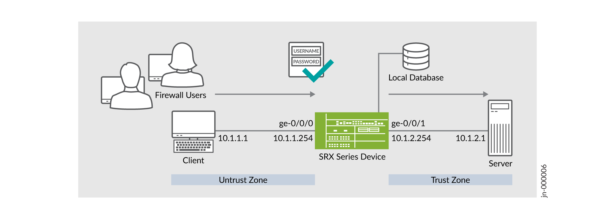
As shown in the topology, firewall users in the untrust zone need to access an external server (IP address 10.1.2.1) in the trust zone. The user authenticates with the security device before accessing the server. The device queries a local database to determine the authentication result. After successful authentication, the security device allows subsequent traffic from the same source IP address until the user's session times out and closes.
In this example, you'll configure the following functionality on the SRX Series Firewall:
-
Configure a user database that is local to the security device in an access profile. Add one or more clients within the profile, representing end users. The client-name represents the username. Enter the password for each user in plain-text format.
- Associate access profile with pass-through or Web firewall authentication methods. Set a customized banner for display to the end user.
- Configure security policy to allow or restrict traffic and apply firewall user authentication for the allowed traffic.
Requirements
This example uses the following hardware and software components:
- An SRX Series Firewall or vSRX Virtual Firewall
- Junos OS Release 21.2R1
Before You Begin:
- Install a valid application identification feature license on your SRX Series Firewall. See Installing and Verifying Licenses for an Application Signature Package.
- Install application signature database on the SRX Series Firewall. See Downloading and Installing the Junos OS Application Signature Package.
Configuration of SRX Firewall Users with Traditional Policy and Unified Policy
| Scenarios | Policies | Workflow When User Initiates a Session | Result |
|---|---|---|---|
| Authentication with traditional security policy and unknown user | Policy P1
|
|
Permits an unauthenticated user after a successful firewall user authentication. |
| Authentication with unified policy and an authenticated user | Policy P2
|
|
Permits an authenticated user without firewall user authentication. |
| Authentication with unified policy | Policy P3
|
|
Permits traffic with firewall user authentication. |
To redirect the traffic from an unauthenticated-user to a UAC captive portal for authentication, see Example: Configuring a User Role Firewall on an SRX Series Device.
CLI Quick Configuration
To quickly configure this example on your SRX Series Firewall, copy the following commands, paste them into a text file. Remove any line breaks, change any details necessary to match your network configuration, and then copy and paste the commands into the CLI at the [edit] hierarchy level.
set services ssl termination profile ssl-a server-certificate SERVER-CERTIFICATE-1
set security policies from-zone untrust to-zone trust policy p1 match source-address any
set security policies from-zone untrust to-zone trust policy p1 match destination-address any
set security policies from-zone untrust to-zone trust policy p1 match application junos-http
set security policies from-zone untrust to-zone trust policy p1 match application junos-https
set security policies from-zone untrust to-zone trust policy p1 match source-identity unauthenticated-user
set security policies from-zone untrust to-zone trust policy p1 match source-identity unknown-user
set security policies from-zone untrust to-zone trust policy p1 then permit firewall-authentication user-firewall access-profile PROFILE-1
set security policies from-zone untrust to-zone trust policy p1 then permit firewall-authentication user-firewall ssl-termination-profile ssl-a
set security policies from-zone untrust to-zone trust policy p1 then log session-init
set security policies from-zone untrust to-zone trust policy p1 then log session-close
set security policies from-zone untrust to-zone trust policy p2 match source-address any
set security policies from-zone untrust to-zone trust policy p2 match destination-address any
set security policies from-zone untrust to-zone trust policy p2 match application any
set security policies from-zone untrust to-zone trust policy p2 match source-identity authenticated-user
set security policies from-zone untrust to-zone trust policy p2 match dynamic-application junos:GOOGLE
set security policies from-zone untrust to-zone trust policy p2 then permit
set security policies from-zone untrust to-zone trust policy p3 match source-address any
set security policies from-zone untrust to-zone trust policy p3 match destination-address any
set security policies from-zone untrust to-zone trust policy p3 match application any
set security policies from-zone untrust to-zone trust policy p3 match dynamic-application junos:YAHOO
set security policies from-zone untrust to-zone trust policy p3 then permit firewall-authentication user-firewall access-profile PROFILE-1
set security zones security-zone trust interfaces ge-0/0/1.0 host-inbound-traffic system-services all
set security zones security-zone trust interfaces ge-0/0/1.0 host-inbound-traffic protocols all
set security zones security-zone untrust interfaces ge-0/0/0.0 host-inbound-traffic system-services all
set security zones security-zone untrust interfaces ge-0/0/0.0 host-inbound-traffic protocols all
set interfaces ge-0/0/0 unit 0 family inet address 10.1.1.254/24
set interfaces ge-0/0/1 unit 0 family inet address 10.1.2.254/24
set access profile PROFILE-1 client CLIENT-1 client-group GROUP-1
set access profile PROFILE-1 client CLIENT-1 firewall-user password "$ABC123"
set access profile PROFILE-1 client CLIENT-2 client-group GROUP-1
set access profile PROFILE-1 client CLIENT-2 firewall-user password "$ABC123"
set access profile PROFILE-1 session-options client-idle-timeout 10
set access firewall-authentication pass-through default-profile PROFILE-1
set access firewall-authentication web-authentication default-profile PROFILE-1
Step-by-Step Procedure
-
Configure interfaces.
[edit]
user@host# set interfaces ge-0/0/0 unit 0 family inet address 10.1.1.254/24
user@host# set interfaces ge-0/0/1 unit 0 family inet address 10.1.2.254/24
-
Create security zones and assign the interfaces.
[edit]
user@host# set security zones security-zone trust interfaces ge-0/0/1.0 host-inbound-traffic system-services all
user@host# set security zones security-zone trust interfaces ge-0/0/1.0 host-inbound-traffic protocols all
user@host# set security zones security-zone untrust interfaces ge-0/0/0.0 host-inbound-traffic system-services all
user@host# set security zones security-zone untrust interfaces ge-0/0/0.0 host-inbound-traffic protocols all
-
Set up access profile and add user details.
[edit]
user@host# set access profile PROFILE-1 client CLIENT-1 client-group GROUP-1
user@host# set access profile PROFILE-1 client CLIENT-1 firewall-user password "$9$2ngZjHkPQ39.PhrvLVb.P5Tz6"
user@host# set access profile PROFILE-1 client CLIENT-2 client-group GROUP-1
user@host# set access profile PROFILE-1 client CLIENT-2 firewall-user password "$9$/Bv59pBIRSleWB17-ws4o"
user@host# set access profile PROFILE-1 session-options client-idle-timeout 10
We've added two users CLIENT-1 and CLIENT-2 with passwords and assigned these users to client-group GROUP-1.
-
Configure authentication methods and assign the access profile.
[edit]
user@host# set access firewall-authentication pass-through default-profile PROFILE-1
user@host# set access firewall-authentication web-authentication default-profile PROFILE-1
-
Configure an SSL termination profile.
[edit]
user@host# set services ssl termination profile ssl-a server-certificate SERVER-CERTIFICATE-1
-
Configure a security policy to permit unauthenticated users with firewall user authentication.
[edit]
user@host# set security policies from-zone untrust to-zone trust policy p1 match source-address any
user@host# set security policies from-zone untrust to-zone trust policy p1 match destination-address any
user@host# set security policies from-zone untrust to-zone trust policy p1 match application junos-http
user@host# set security policies from-zone untrust to-zone trust policy p1 match application junos-https
user@host# set security policies from-zone untrust to-zone trust policy p1 match source-identity unauthenticated-user
user@host# set security policies from-zone untrust to-zone trust policy p1 match source-identity unknown-user
user@host# set security policies from-zone untrust to-zone trust policy p1 match source-identity unknown-user
user@host# set security policies from-zone untrust to-zone trust policy p1 then permit firewall-authentication user-firewall access-profile PROFILE-1
user@host# set security policies from-zone untrust to-zone trust policy p1 then permit firewall-authentication user-firewall ssl-termination-profile ssl-a
user@host# set security policies from-zone untrust to-zone trust policy p1 then log session-init
user@host# set security policies from-zone untrust to-zone trust policy p1 then log session-close
-
Configure a security policy to permit authenticated users without firewall user authentication.
[edit]
user@host# set security policies from-zone untrust to-zone trust policy p2 match source-address any
user@host# set security policies from-zone untrust to-zone trust policy p2 match destination-address any
user@host# set security policies from-zone untrust to-zone trust policy p2 match application any
user@host# set security policies from-zone untrust to-zone trust policy p2 match source-identity authenticated-user
user@host# set security policies from-zone untrust to-zone trust policy p2 match dynamic-application junos:GOOGLE
user@host# set security policies from-zone untrust to-zone trust policy p2 then permit
-
Configure a security policy to permit the traffic with firewall user authentication.
[edit]
user@host# set security policies from-zone untrust to-zone trust policy p3 match source-address any
user@host# set security policies from-zone untrust to-zone trust policy p3 match destination-address any
user@host# set security policies from-zone untrust to-zone trust policy p3 match application any
user@host# set security policies from-zone untrust to-zone trust policy p3 match dynamic-application junos:YAHOO
user@host# set security policies from-zone untrust to-zone trust policy p3 then permit firewall-authentication user-firewall access-profile PROFILE-1
user@host#
- Add an entry to a local authentication table. Note that each entry must
include an IP address.
user@host> request security user-identification local-authentication-table add user-name CLIENT-1 ip-address 10.1.1.1
Results
From configuration mode, confirm your configuration by entering the show security command. If the output does not display the intended configuration, repeat the configuration instructions in this example to correct it.
[edit ]user@host# show security policies
from-zone untrust to-zone trust {
policy p1 {
match {
source-address any;
destination-address any;
application [ junos-http junos-https ];
source-identity [ unauthenticated-user unknown-userset unknown-user ];
}
then {
permit {
firewall-authentication {
user-firewall {
access-profile PROFILE-1;
ssl-termination-profile ssl-a;
}
}
}
log {
session-init;
session-close;
}
}
}
policy p2 {
match {
source-address any;
destination-address any;
application any;
source-identity authenticated-user;
dynamic-application junos:GOOGLE;
}
then {
permit;
}
}
policy p3 {
match {
source-address any;
destination-address any;
application any;
dynamic-application junos:YAHOO;
}
then {
permit {
firewall-authentication {
user-firewall {
access-profile PROFILE-1;
}
}
}
}
}
}
user@host# show  security zones
security-zone trust {
    interfaces {
        ge-0/0/1.0 {
            host-inbound-traffic {
                system-services {
                    all;
                }
                protocols {
                    all;
                }
            }
        }
    }
}
security-zone untrust {
    interfaces {
        ge-0/0/0.0 {
            host-inbound-traffic {
                system-services {
                    all;
                }
                protocols {
                    all;
                }
            }
        }
    }
}
user@host# show interfaces
interfaces {
    ge-0/0/0 {
        unit 0 {
            family inet {
                address 10.1.1.254/24;
            }
        }
    }
    ge-0/0/1 {
        unit 0 {
            family inet {
                address 10.1.2.254/24;
            }
        }
    }
[edit]
user@host# show access
profile PROFILE-1 {
    client CLIENT-1 {
        client-group GROUP-1;
        firewall-user {
            password "$9$2ngZjHkPQ39.PhrvLVb.P5Tz6"; ## SECRET-DATA
        }
    }
    client CLIENT-2 {
        client-group GROUP-1;
        firewall-user {
            password "$9$/Bv59pBIRSleWB17-ws4o"; ## SECRET-DATA
        }
    }

    session-options {
        client-idle-timeout 10;
    }
}
firewall-authentication {
    pass-through {
        default-profile PROFILE-1;

    web-authentication {
        default-profile PROFILE-1;
    }
}
If
you are done configuring the feature on your device, enter
commit from configuration mode.
Verifying Firewall User Authentication Is Working
To verify that the firewall user authentication is working, open a Web browser on the client machine. Access the server by entering the server IP address 10.1.2.1. The system prompts for the login and password details as shown in Figure 7.
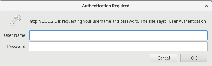
After successfully entering the credentials, you can access the server.
Configuration of Pass-Through Authentication with Unified Policy
any. CLI Quick Configuration
To quickly configure this example on your SRX Series Firewall, copy the following commands, paste them into a text file, remove any line breaks, change any details necessary to match your network configuration, and then copy and paste the commands into the CLI at the [edit] hierarchy level.
set services ssl termination profile ssl-a server-certificate SERVER-CERTIFICATE-1
set interfaces ge-0/0/0 unit 0 family inet address 10.1.1.254/24
set interfaces ge-0/0/1 unit 0 family inet address 10.1.2.254/24
set security policies from-zone untrust to-zone trust policy p1 match source-address any
set security policies from-zone untrust to-zone trust policy p1 match destination-address any
set security policies from-zone untrust to-zone trust policy p1 match application any
set security policies from-zone untrust to-zone trust policy p1 match dynamic-application any
set security policies from-zone untrust to-zone trust policy p1 then permit firewall-authentication pass-through access-profile PROFILE-1
set security policies from-zone untrust to-zone trust policy p1 then permit firewall-authentication pass-through ssl-termination-profile ssl-a
set security policies from-zone untrust to-zone trust policy p1 then log session-init
set security policies from-zone untrust to-zone trust policy p1 then log session-close
set security zones security-zone trust interfaces ge-0/0/1.0 host-inbound-traffic system-services all
set security zones security-zone trust interfaces ge-0/0/1.0 host-inbound-traffic protocols all
set security zones security-zone untrust interfaces ge-0/0/0.0 host-inbound-traffic system-services all
set security zones security-zone untrust interfaces ge-0/0/0.0 host-inbound-traffic protocols all
set access profile PROFILE-1 client CLIENT-1 client-group GROUP-1
set access profile PROFILE-1 client CLIENT-1 firewall-user password "$9$2ngZjHkPQ39.PhrvLVb.P5Tz6"
set access profile PROFILE-1 client CLIENT-2 client-group GROUP-1
set access profile PROFILE-1 client CLIENT-2 firewall-user password "$9$/Bv59pBIRSleWB17-ws4o"
set access profile PROFILE-1 session-options client-idle-timeout 10
set access firewall-authentication pass-through default-profile PROFILE-1
set access firewall-authentication web-authentication default-profile PROFILE-1
Step-by-Step Procedure
-
Configure interfaces.
[edit]
user@host# set interfaces ge-0/0/0 unit 0 family inet address 10.1.1.254/24
user@host# set interfaces ge-0/0/1 unit 0 family inet address 10.1.2.254/24
-
Define security zones and assign interfaces.
[edit]
user@host# set security zones security-zone trust interfaces ge-0/0/1.0 host-inbound-traffic system-services all
user@host# set security zones security-zone trust interfaces ge-0/0/1.0 host-inbound-traffic protocols all
user@host# set security zones security-zone untrust interfaces ge-0/0/0.0 host-inbound-traffic system-services all
user@host# set security zones security-zone untrust interfaces ge-0/0/0.0 host-inbound-traffic protocols all
-
Set up access profile and add user details.
[edit]
user@host# set access profile PROFILE-1 client CLIENT-1 client-group GROUP-1
user@host# set access profile PROFILE-1 client CLIENT-1 firewall-user password "$9$2ngZjHkPQ39.PhrvLVb.P5Tz6"
user@host# set access profile PROFILE-1 client CLIENT-2 client-group GROUP-1
user@host# set access profile PROFILE-1 client CLIENT-2 firewall-user password "$9$/Bv59pBIRSleWB17-ws4o"
user@host# set access profile PROFILE-1 session-options client-idle-timeout 10
We've added two users CLIENT-1 and CLIENT-2 with passwords and assigned the users to client-group GROUP-1.
-
Configure authentication methods and assign the access profile.
[edit]
user@host# set access firewall-authentication pass-through default-profile PROFILE-1
user@host# set access firewall-authentication web-authentication default-profile PROFILE-1
-
Configure an SSL termination profile.
[edit]
user@host# set services ssl termination profile ssl-a server-certificate SERVER-CERTIFICATE-1
-
Configure a security policy with dynamic application as
any.[edit] user@host# set security policies from-zone untrust to-zone trust policy p1 match source-address any user@host# set security policies from-zone untrust to-zone trust policy p1 match destination-address any user@host# set security policies from-zone untrust to-zone trust policy p1 match application any user@host# set security policies from-zone untrust to-zone trust policy p1 match dynamic-application any user@host# set security policies from-zone untrust to-zone trust policy p1 then permit firewall-authentication pass-through access-profile PROFILE-1 user@host# set security policies from-zone untrust to-zone trust policy p1 then permit firewall-authentication pass-through ssl-termination-profile ssl-a user@host# set security policies from-zone untrust to-zone trust policy p1 then log session-init user@host# set security policies from-zone untrust to-zone trust policy p1 then log session-close
Results
From configuration mode, confirm your configuration by entering the show security command. If the output does not display the intended configuration, repeat the configuration instructions in this example to correct it.
[edit]user@host# show security policies]
from-zone untrust to-zone trust {
policy p1 {
match {
source-address any;
destination-address any;
application any;
dynamic-application any;
}
then {
permit {
firewall-authentication {
pass-through {
access-profile PROFILE-1;
ssl-termination-profile ssl-a;
}
}
}
log {
session-init;
session-close;
}
}
}
}
[edit]
user@host# show security zones
security-zone trust {
    interfaces {
        ge-0/0/1.0 {
            host-inbound-traffic {
                system-services {
                    all;
                }
                protocols {
                    all;
                }
            }
        }
    }
}
security-zone untrust {
    interfaces {
        ge-0/0/0.0 {
            host-inbound-traffic {
                system-services {
                    all;
                }
                protocols {
                    all;
                }
            }
        }
    }
}
[edit]
user@host# show interfaces
ge-0/0/0 {
    unit 0 {
        family inet {
            address 10.1.1.254/24;
        }
    }
}
ge-0/0/1 {
    unit 0 {
        family inet {
            address 10.1.2.254/24;
        }
    }
}
[edit]
user@host# show access
profile PROFILE-1 {
    client CLIENT-1 {
        client-group GROUP-1;
        firewall-user {
            password "$9$2ngZjHkPQ39.PhrvLVb.P5Tz6"; ## SECRET-DATA
        }
    }
    client CLIENT-2 {
        client-group GROUP-1;
        firewall-user {
            password "$9$/Bv59pBIRSleWB17-ws4o"; ## SECRET-DATA
        }
    }
    session-options {
        client-idle-timeout 10;
    }
}
firewall-authentication {
    pass-through {
        default-profile PROFILE-1;
    }
    web-authentication {
        default-profile PROFILE-1;
    }
}
If
you are done configuring the feature on your device, enter
commit from configuration mode.
Verifying Pass-Through Authentication Is Working
To verify that firewall user authentication is working, open a Web browser on the client machine. Access the server by entering server IP address 10.1.2.1. The system prompts for login and password details as shown in Figure 8.
After successfully entering the credentials, you can access the server.
Configuration of Captive Portal Authentication with Unified Policy
CLI Quick Configuration
To quickly configure this example on your SRX Series Firewall, copy the following commands, paste them into a text file, remove any line breaks, change any details necessary to match your network configuration, and then copy and paste the commands into the CLI at the [edit] hierarchy level.
set system services web-management http interface ge-0/0/0.0
set system services web-management https system-generated-certificate
set system services web-management https interface ge-0/0/0.0
set security policies from-zone untrust to-zone trust policy p1 match source-address any
set security policies from-zone untrust to-zone trust policy p1 match destination-address any
set security policies from-zone untrust to-zone trust policy p1 match application junos-http
set security policies from-zone untrust to-zone trust policy p1 match application junos-https
set security policies from-zone untrust to-zone trust policy p1 match dynamic-application junos:HTTP
set security policies from-zone untrust to-zone trust policy p1 match dynamic-application junos:SSH
set security policies from-zone untrust to-zone trust policy p1 then permit firewall-authentication web-authentication
set security policies from-zone untrust to-zone trust policy p1 then log session-init
set security policies from-zone untrust to-zone trust policy p1 then log session-close
set security zones security-zone trust interfaces ge-0/0/1.0 host-inbound-traffic system-services all
set security zones security-zone trust interfaces ge-0/0/1.0 host-inbound-traffic protocols all
set security zones security-zone untrust interfaces ge-0/0/0.0 host-inbound-traffic system-services all
set security zones security-zone untrust interfaces ge-0/0/0.0 host-inbound-traffic protocols all
set interfaces ge-0/0/0 unit 0 family inet address 10.1.1.254/24
set interfaces ge-0/0/0 unit 0 family inet address 10.1.1.253/24 web-authentication http
set interfaces ge-0/0/0 unit 0 family inet address 10.1.1.253/24 web-authentication https
set interfaces ge-0/0/1 unit 0 family inet address 10.1.2.254/24
set access profile PROFILE-1 client CLIENT-1 client-group GROUP-1
set access profile PROFILE-1 client CLIENT-1 firewall-user password "$9$2ngZjHkPQ39.PhrvLVb.P5Tz6"
set access profile PROFILE-1 client CLIENT-2 client-group GROUP-1
set access profile PROFILE-1 client CLIENT-2 firewall-user password "$9$/Bv59pBIRSleWB17-ws4o"
set access profile PROFILE-1 session-options client-idle-timeout 10
set access firewall-authentication pass-through default-profile PROFILE-1
set access firewall-authentication web-authentication default-profile PROFILE-1
set access firewall-authentication web-authentication banner success "WELCOME to JUNIPER HTTP SESSION"
Step-by-Step Procedure
-
Create interfaces.
[edit]
user@host# set interfaces ge-0/0/0 unit 0 family inet address 10.1.1.254/24
user@host# set interfaces ge-0/0/0 unit 0 family inet address 10.1.1.253/24 web-authentication http
user@host# set interfaces ge-0/0/0 unit 0 family inet address 10.1.1.253/24 web-authentication https
user@host# set interfaces ge-0/0/1 unit 0 family inet address 10.1.2.254/24
Use a secondary IP address for the Web authentication. In this example, we're using 10.1.1.253/24 for web authentication. Note that the secondary IP address must use the same subnet as primary IP address.
-
Create security zones and assign interfaces.
[edit]
user@host# set security zones security-zone trust interfaces ge-0/0/1.0 host-inbound-traffic system-services all
user@host# set security zones security-zone trust interfaces ge-0/0/1.0 host-inbound-traffic protocols all
user@host# set security zones security-zone untrust interfaces ge-0/0/0.0 host-inbound-traffic system-services all
user@host# set security zones security-zone untrust interfaces ge-0/0/0.0 host-inbound-traffic protocols all
- Enable the interface for the Web
authentication.
[edit]
user@host# set system services web-management http interface ge-0/0/0.0
user@host# set system services web-management https system-generated-certificate
-
Set up access profile and add user details.
[edit]
user@host# set access profile PROFILE-1 client CLIENT-1 client-group GROUP-1
user@host# set access profile PROFILE-1 client CLIENT-1 firewall-user password "$9$2ngZjHkPQ39.PhrvLVb.P5Tz6"
user@host# set access profile PROFILE-1 client CLIENT-2 client-group GROUP-1
user@host# set access profile PROFILE-1 client CLIENT-2 firewall-user password "$9$/Bv59pBIRSleWB17-ws4o"
user@host# set access profile PROFILE-1 session-options client-idle-timeout 10
We've added two users CLIENT-1 and CLIENT-2 with passwords and assigned the users to client-group GROUP-1.
-
Configure Web authentication properties
[edit]
user@host# set access firewall-authentication web-authentication default-profile PROFILE-1
user@host# set access firewall-authentication web-authentication banner success "WELCOME to JUNIPER HTTP SESSION"
-
Create a security policy with dynamic-application.
[edit]
user@host# set security policies from-zone untrust to-zone trust policy p1 match source-address any
user@host# set security policies from-zone untrust to-zone trust policy p1 match destination-address any
user@host# set security policies from-zone untrust to-zone trust policy p1 match application junos-http
user@host# set security policies from-zone untrust to-zone trust policy p1 match application junos-https
user@host# set security policies from-zone untrust to-zone trust policy p1 match dynamic-application junos:HTTP
user@host# set security policies from-zone untrust to-zone trust policy p1 then permit firewall-authentication web-authentication
user@host# set security policies from-zone untrust to-zone trust policy p1 then log session-init
user@host# set security policies from-zone untrust to-zone trust policy p1 then log session-close
Results
From configuration mode, confirm your configuration by entering the show security command. If the output does not display the intended configuration, repeat the configuration instructions in this example to correct it.
[edit]user@host# show security policies
from-zone untrust to-zone trust {
policy p1 {
match {
source-address any;
destination-address any;
application [ junos-http junos-https ];
dynamic-application [ junos:HTTP junos:SSH ];
}
then {
permit {
firewall-authentication {
web-authentication;
}
}
log {
session-init;
session-close;
}
}
}
}
[edit]
user@host# show security zones
security-zone trust {
    interfaces {
        ge-0/0/1.0 {
            host-inbound-traffic {
                system-services {
                    all;
                }
                protocols {
                    all;
                }
            }
        }
    }
}
security-zone untrust {
    interfaces {
        ge-0/0/0.0 {
            host-inbound-traffic {
                system-services {
                    all;
                }
                protocols {
                    all;
                }
            }
        }
    }
}
[edit]
user@host# show interfaces
ge-0/0/0 {
    unit 0 {
        family inet {
            address 10.1.1.254/24;
            address 10.1.1.253/24 {
                web-authentication {
                    http;
                    https;
                }
            }
        }
    }
}
ge-0/0/1 {
    unit 0 {
        family inet {
            address 10.1.2.254/24;
        }
    }
}
[edit]
user@host# show access
profile PROFILE-1 {
    client CLIENT-1 {
        client-group GROUP-1;
        firewall-user {
            password "$9$2ngZjHkPQ39.PhrvLVb.P5Tz6"; ## SECRET-DATA
        }
    }
    client CLIENT-2 {
        client-group GROUP-1;
        firewall-user {
            password "$9$/Bv59pBIRSleWB17-ws4o"; ## SECRET-DATA
        }
    }
    session-options {
        client-idle-timeout 10;
    }
}
firewall-authentication {
    pass-through {
        default-profile PROFILE-1;
        }
    }
    web-authentication {
        default-profile PROFILE-1;
        banner {
            success "WELCOME to JUNIPER HTTP SESSION";
        }
    }
}
[edit]
user@host# show system services
ssh {
    root-login allow;
}
web-management {
    http {
        interface [ fxp0.0 ge-0/0/0.0 ];
    }
    https {
        system-generated-certificate;
        interface [ fxp0.0 ge-0/0/0.0 ];
    }
}
If
you are done configuring the feature on your device, enter
commit from configuration mode.
Verifying Web Authentication Is Working
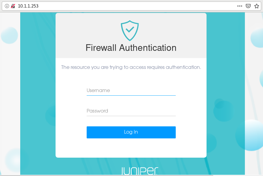
To verify that Web authentication is working, open a Web browser on the client machine. First, access the security device using a Web browser. Use the IP address 10.1.1.253 which we've configured for Web authentication. The device prompts for a username and password as shown in Figure 9.
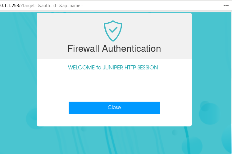
After successful authentication, the system displays the configured banner as shown in Figure 10, and you can get access to the server.
Verification
Monitoring Firewall Users
Purpose
Display firewall authentication user history to verify the firewall users details.
Action
From operational mode, enter these show commands:
user@host> show security firewall-authentication users
Firewall authentication data:
  Total users in table: 1
          Id Source Ip                         Src zone Dst zone Profile    Age Status   User
          15 10.1.1.1                          N/A      N/A      PROFILE-     1 Success  CLIENT-2
user@host> show security firewall-authentication users identifier 16
Username: CLIENT-2
Source IP: 10.1.1.1
Authentication state: Success
Authentication method: User-firewall using HTTP
Age: 1
Access time remaining: 9
Lsys: root-logical-system
Source zone: N/A
Destination zone: N/A
Access profile: PROFILE-1
Interface Name: ge-0/0/0.0
Bytes sent by this user: 56986
Bytes received by this user: 436401
Client-groups: GROUP-1
lab@vSRX-01> show security firewall-authentication users identifier 15
Username: CLIENT-2
Source IP: 10.1.1.1
Authentication state: Success
Authentication method: Web-authentication using HTTP
Age: 2
Access time remaining: 8
Lsys: root-logical-system
Source zone: N/A
Destination zone: N/A
Access profile: PROFILE-1
Interface Name: ge-0/0/0.0
Bytes sent by this user: 0
Bytes received by this user: 0
Client-groups: GROUP-1
user@host> show security firewall-authentication history
History of firewall authentication data:
  Authentications: 2
          Id Source Ip                         Date       Time     Duration   Status   User
           0 10.1.1.1                          2021-05-12 06:44:26 0:00:59    Failed
          14 10.1.1.1                          2021-05-12 07:33:43 0:10:00    Success  CLIENT-2
Meaning
Command output provides details such as logged in users, authentication method used, profile applied, login attempts and so on.
Verifying Security Policy Utilization Details
Purpose
Display the utility rate of security policies according to the number of hits received.
Action
From operational mode, enter these show commands:
user@host> show security policies hit-count
Logical system: root-logical-system
Index   From zone        To zone           Name           Policy count  Action
1       untrust          trust             p2             2             Permit
Meaning
Command output provides details on the security policies applied on the traffic.
Example: Configure External Authentication Servers
This example shows how to configure a device for external authentication.
Requirements
Before you begin, create an authentication user group.
Overview
You can put several user accounts together to form a user group, which you can store on the local database or on a RADIUS, an LDAP, or a SecurID server. When you reference an authentication user group and an external authentication server in a policy, the traffic matching the policy provokes an authentication check.
This example shows how access profile Profile-1 is configured for external authentication. Two RADIUS servers and one LDAP server are configured in the access profile. However, the order of authentication specifies RADIUS server only, so if the RADIUS server authentication fails, then the firewall user fails to authenticate. The local database is not accessed.
If the firewall clients are authenticated by the RADIUS server, then the group-membership VSA returned by the RADIUS server should contain alpha, beta, or gamma client groups in the RADIUS server configuration or in the access profile, Profile-1. Access profiles store usernames and passwords of users or point to external authentication servers where such information is stored.
Configuration
Procedure
CLI Quick Configuration
To quickly configure this example, copy the following commands to a text file, remove any line breaks, change any details necessary to match your network configuration, copy and paste the commands into the CLI at the [edit] hierarchy level, and then enter commit from configuration mode.
set access profile Profile-1 authentication-order radius
set access profile Profile-1 client Client-1 client-group alpha
set access profile Profile-1 client Client-1 client-group beta
set access profile Profile-1 client Client-1 client-group gamma
set access profile Profile-1 client Client-1 firewall-user password pwd
set access profile Profile-1 client Client-2 client-group alpha
set access profile Profile-1 client Client-2 client-group beta
set access profile Profile-1 client Client-2 firewall-user password pwd
set access profile Profile-1 client Client-3 firewall-user password pwd
set access profile Profile-1 client Client-4 firewall-user password pwd
set access profile Profile-1 session-options client-group alpha
set access profile Profile-1 session-options client-group beta
set access profile Profile-1 session-options client-group gamma
set access profile Profile-1 session-options client-idle-timeout 255
set access profile Profile-1 session-options client-session-timeout 4
set access profile Profile-1 ldap-options base-distinguished-name CN=users,DC=junos,DC=juniper,DC=net
set access profile Profile-1 ldap-options search search-filter sAMAccountName=
set access profile Profile-1 ldap-options search admin-search distinguished-name cn=administrator,cn=users,dc=junos,dc=juniper,dc=net
set access profile Profile-1 ldap-options search admin-search password pwd
set access profile Profile-1 ldap-server 203.0.113.39/24
set access profile Profile-1 radius-server 203.0.113.62/24  secret example-secret
set access profile Profile-1 radius-server 203.0.113.62/24  retry 10
set access profile Profile-1 radius-server 203.0.113.27/24  secret juniper
Step-by-Step Procedure
The following example requires you to navigate various levels in the configuration hierarchy. For instructions on how to do that, see Using the CLI Editor in Configuration Mode.
To configure a device for external authentication:
Specify the RADIUS server for external authentication order.
[edit]
user@host# set access profile Profile-1 authentication-order radius
Configure Client1-4 firewall users and assign the Client-1 firewall user and Client-2 firewall user to client groups.
[edit access profile Profile-1]
user@host# set client Client-1 client-group alpha
user@host# set client Client-1 client-group beta
user@host# set client Client-1 client-group gamma
user@host# set client Client-1 firewall-user password pwd
user@host# set client Client-2 client-group alpha
user@host# set client Client-2 client-group beta
user@host# set client Client-2 firewall-user password pwd
user@host# set client Client-3 firewall-user password pwd
user@host# set client Client-4 firewall-user password pwd
Configure client groups in the session options.
[edit access profile Profile-1]
user@host# set session-options client-group alpha
user@host# set session-options client-group beta
user@host# set session-options client-group gamma
user@host# set session-options client-idle-timeout 255
user@host# set session-options client-session-timeout 4
Configure the IP address for the LDAP server and server options.
[edit access profile Profile-1]
user@host# set ldap-options base-distinguished-name CN=users,DC=junos,DC=mycompany,DC=net
user@host# set ldap-options search search-filter sAMAccountName=
user@host# set ldap-options search admin-search password pwd
user@host# set ldap-options search admin-search distinguished-name cn=administrator,cn=users,dc=junos,dc=mycompany,dc=net
user@host# set ldap-server 203.0.113.39/24
Configure the IP addresses for the two RADIUS servers.
[edit access profile Profile-1]
user@host# set radius-server 203.0.113.62/24  secret pwd
user@host# set radius-server 203.0.113.62/24  retry 10
user@host# set radius-server 203.0.113.27/24 secret pwd
Results
From configuration mode, confirm your configuration
by entering the show access profile Profile-1 command.
If the output does not display the intended configuration, repeat
the configuration instructions in this example to correct it.
user@host# show access profile Profile-1
authentication-order radius;
client Client-1 {
    client-group [ alpha beta gamma ];
    firewall-user {
        password "$ABC123"; ## SECRET-DATA
    }
}
client Client-2 {
    client-group [ alpha beta ];
    firewall-user {
        password "$ABC123"; ## SECRET-DATA
    }
}
client Client-3 {
    firewall-user {
        password "$ABC123"; ## SECRET-DATA
    }
}
client Client-4 {
    firewall-user {
        password "$ABC123"; ## SECRET-DATA
    }
}
session-options {
    client-group [ alpha beta gamma ];
    client-idle-timeout 255;
    client-session-timeout 4;
}
ldap-options {
    base-distinguished-name CN=users,DC=junos,DC=juniper,DC=net;
    search {
        search-filter sAMAccountName=;
        admin-search {
            distinguished-name cn=administrator,cn=users,dc=junos,
							dc=mycompany,dc=net; password "$ABC123"; ## SECRET-DATA
        }
    }
}
ldap-server {
    203.0.113.39/24 ;
}
radius-server {
    203.0.113.62/24  {
        secret "$ABC123"; ## SECRET-DATA
        retry 10;
    }
    203.0.113.27/24  {
        secret "$ABC123"; ## SECRET-DATA
    }
}
If you are done configuring the device, enter commit from configuration mode.
Example: Configure Client Groups
This example shows how to configure a local user for client groups in a profile.
Requirements
Before you begin, create an access profile.
Overview
A client group is a list of groups to which the client belongs. As with client-idle timeout, a client group is used only if the external authentication server does not return a value in its response (for example, LDAP servers do not return such information).
This example shows how to configure a local user called Client-1
for client groups G1, G2, and G3 in a profile called Managers. Within
this example, client groups are configured for a client. If a client
group is not defined for the client, then the client group under the access profile session-options hierarchy is used.
Configuration
Procedure
CLI Quick Configuration
To quickly configure this example, copy the following commands to a text file, remove any line breaks, change any details necessary to match your network configuration, copy and paste the commands into the CLI at the [edit] hierarchy level, and then enter commit from configuration mode.
set access profile Managers client Client-1 client-group G1set access profile Managers client Client-1 client-group G2set access profile Managers client Client-1 client-group G3set access profile Managers client Client-1 firewall-user password pwdset access profile Managers session-options client-group G1set access profile Managers session-options client-group G2set access profile Managers session-options client-group G3
Step-by-Step Procedure
The following example requires you to navigate various levels in the configuration hierarchy. For instructions on how to do that, see Using the CLI Editor in Configuration Mode.
To configure a local user for client groups in a profile:
Configure the firewall user profile Managers, and assign client groups to it.
user@host# edit access profile Managers
[edit access profile Managers]
user@host# set client Client-1 client-group G1
user@host# set client Client-1 client-group G2
user@host# set client Client-1 client-group G3
user@host# set client Client-1 firewall-user password pwd
Configure client groups in the session options.
[edit access profile Managers]
user@host# set session-options client-group G1
user@host# set session-options client-group G2
user@host# set session-options client-group G3
Results
Confirm your configuration by entering the show
access profile Managers command from configuration mode. If
the output does not display the intended configuration, repeat the
configuration instructions in this example to correct it.
user@host# show access profile Managers

client Client-1 {
    client-group [ G1 G2 G3 ];
    firewall-user {
        password "$ABC123"; ## SECRET-DATA
    }
}
session-options {
    client-group [ G1 G2 G3 ];
}
If you are done configuring the device, enter commit from configuration mode.
Example: Customize Banner
This example shows how to customize the banner text that appears in the browser.
Requirements
Before you begin, create an access profile.
Overview
A banner is a message that appears on a monitor in different places depending on the type of login. This example shows how to change the banner that appears in the browser to indicate that a user has successfully authenticated after successfully logging in through Web authentication. The new message is “Web authentication is successful.” If the authentication fails, then the new message reads “Authentication failed.”
Configuration
Procedure
CLI Quick Configuration
To quickly configure this example, copy the following commands to a text file, remove any line breaks, change any details necessary to match your network configuration, copy and paste the commands into the CLI at the [edit] hierarchy level, and then enter commit from configuration mode.
set access firewall-authentication pass-through default-profile Profile-1set access firewall-authentication pass-through ftp banner fail “ Authentication failed”set access firewall-authentication web-authentication default-profile Profile-1set access firewall-authentication web-authentication banner success “ Web authentication is successful”
Step-by-Step Procedure
The following example requires you to navigate various levels in the configuration hierarchy. For instructions on how to do that, see Using the CLI Editor in Configuration Mode.
To customize the banner text that appears in the browser:
Specify the banner text for failed pass-through authentication through FTP.
[edit]
user@host# set access firewall-authentication pass-through default-profile Profile-1
user@host# set access firewall-authentication pass-through ftp banner fail “ Authentication failed”
Specify the banner text for successful Web authentication.
[edit]
user@host# set access web-authentication default-profile Profile-1
user@host# set access web-authentication banner success “ Web authentication is successful”
Results
From configuration mode, confirm your configuration
by entering the show access firewall-authentication command.
If the output does not display the intended configuration, repeat
the configuration instructions in this example to correct it.
user@host# show access firewall-authentication
pass-through {
    default-profile Profile-1;
    ftp {
        banner {
            fail "Authentication failed";
        }
    }
}
web-authentication {
    default-profile Profile-1;
    banner {
        success "Web authentication is successful";
    }
}
If you are done configuring the device, enter commit from configuration mode.
Example: Configure Mutual TLS (mTLS) Authentication for SRX Captive Portal
Learn how to configure mutual TLS (mTLS) authentication.
Use this example to configure and verify mutual Transport Layer Security (mTLS) authentication on your firewall. In this example, we use firewall to refer to a Juniper Networks® SRX Series Firewall or a Juniper Networks® vSRX Virtual Firewall (vSRX3.0). With this configuration, an user can authenticate without a password. User authentication happens through validation of the client/server certificates with the help of a public-private key pair.
To configure mTLS as shown in this example, an administrator must generate the following certificates:
-
CA certificate—Run the CA certificate on your firewall and client browser.
-
Server certificate—Generate a server certificate on your firewall by using the domain1.com mTLS server. Sign the server certificate with a CA certificate configured on your firewall.
-
Client certificate—Generate a client certificate on your client browser and sign the client certificate with a CA certificate configured on your firewall.
|
Reading Time |
Less than an hour. |
|
Configuration Time |
Less than an hour. |
- Example Prerequisites
- Before You Begin
- Functional Overview
- Topology Overview
- Topology Illustration
- Step-By-Step Configuration on Device-Under-Test (DUT)
- Appendix 1:
setCommands on All Devices - Generate Key Certificates for Client and Server
- Verification
Example Prerequisites
|
Hardware requirements |
Juniper Networks® SRX Series Firewall or Juniper Networks® vSRX Virtual Firewall (vSRX3.0) |
|
Software requirements |
Junos OS Release 23.4R1 or later |
Before You Begin
|
Benefits |
With mTLS authentication, you can:
|
|
Know more |
Identity Aware Firewall |
|
Learn more |
Firewall User Authentication |
Functional Overview
This section provides a summary of the configuration components in this example.
|
Technologies used |
To establish the mTLS authentication, you must configure:
|
|
Primary verification tasks |
Verify mTLS authentication. |
Topology Overview
In this example, a client connects to a server through a firewall. In mTLS authentication, the client and the server verify each other's certificate by exchanging information over an encrypted TLS connection.
The firewall redirects unauthenticated clients to domain1.com upon connection to the server. This process avoids certificate errors because the CA certificate and server certificate for domain1.com are pre-installed on the firewall. The CA certificate is pre-installed on the client's browser.
Use mTLS authentication to bypass manual entry of user credentials for captive portal authentication. Ensure a valid user is configured against the Lightweight Directory Access Protocol (LDAP) profile to retrieve user information and authorization from Active Directory. When firewall authentication is applied in the policy, JIMS configuration is required.
|
Hostname |
Role |
Function |
|---|---|---|
|
Client |
Service requester |
Initiates session with server through the SRX Series Firewall. |
|
SRX Series Firewall |
Firewall |
Encrypts and decrypts packets for the client. |
|
Server |
Server |
Responds to a client's request. |
|
Active Directory |
Identity source |
Active Directory as Identity Source defines the integration of SRX Series Firewall, vSRX Virtual Firewall, Juniper Networks® cSRX Container Firewall, or Juniper Networks® NFX Series Network Services Platform with Microsoft Windows Active Directory. For more information, see Active Directory as Identity Source. |
|
JIMS |
Windows service application |
Juniper® Identity Management Service (JIMS) is a Windows service application designed to collect and manage user, device, and group information from Active Directory domains. For more information, see JIMS with SRX Series Firewall. |
Topology Illustration
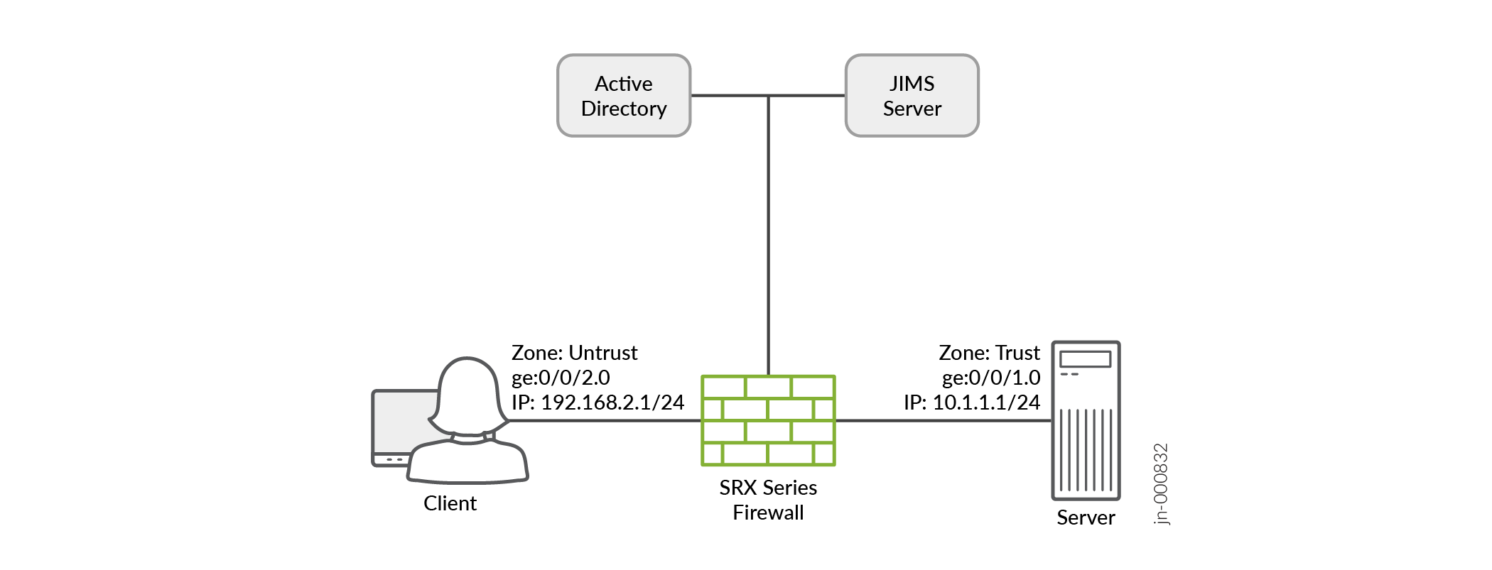
Step-By-Step Configuration on Device-Under-Test (DUT)
Configure the required interfaces.
set interfaces ge-0/0/2 unit 0 family inet address 192.168.2.1/24 web-authentication https
set interfaces ge-0/0/1 unit 0 family inet address 10.1.1.1/24
Configure the security zones and assign interfaces to the zones.
set security zones security-zone untrust host-inbound-traffic system-services ike
set security zones security-zone untrust host-inbound-traffic system-services https
set security zones security-zone untrust host-inbound-traffic system-services tcp-encap
set security zones security-zone untrust interfaces ge-0/0/2.0
set security zones security-zone trust interfaces ge-0/0/1.0
Configure an access profile.
set access profile profile1 client user1 client-group group1
set access profile profile1 client user1 client-group group2
set access profile profile1 client user1 firewall-user password "$9$dPb4ZjHmzF/k.uO"
Configure a security policy to permit unauthenticated users with firewall user authentication.
set security policies from-zone untrust to-zone trust policy p1 match source-address any
set security policies from-zone untrust to-zone trust policy p1 match destination-address any
set security policies from-zone untrust to-zone trust policy p1 match application any
set security policies from-zone untrust to-zone trust policy p1 match source-identity unauthenticated-user
set security policies from-zone untrust to-zone trust policy p1 match source-identity unknown-user
set security policies from-zone untrust to-zone trust policy p1 then permit firewall-authentication user-firewall access-profile profile1
set security policies from-zone untrust to-zone trust policy p1 then permit firewall-authentication user-firewall web-redirect-to-https
set security policies from-zone untrust to-zone trust policy p1 then permit firewall-authentication user-firewall web-authentication-server domain1.com:8443
set security policies from-zone untrust to-zone trust policy p1 then permit firewall-authentication push-to-identity-management
set security policies from-zone untrust to-zone trust policy p1 then log session-close
Configure a security policy to permit authenticated users without firewall user authentication.
set security policies from-zone untrust to-zone trust policy p2 match source-address any
set security policies from-zone untrust to-zone trust policy p2 match destination-address any
set security policies from-zone untrust to-zone trust policy p2 match application any
set security policies from-zone untrust to-zone trust policy p2 match source-identity authenticated-user
set security policies from-zone untrust to-zone trust policy p2 then permit
set security policies from-zone untrust to-zone trust policy p2 then log session-close
Configure a ca-profile.
set security pki ca-profile ca_domain1
set security pki ca-profile ca_domain1 ca-identity ca_domain1_id
Configure an mTLS profile.
set security firewall-authentication mtls-profile ma2 subject CN=test1client.*
set security firewall-authentication mtls-profile-fallback-password
Configure
web-managementto start mTLS on the firewall on which you run the domain1.com server certificate.set system services web-management https interface ge-0/0/2.0 set system services web-management https pki-local-certificate srx_domain1.com set system services web-management https virtual-domain domain1.com pki-local-certificate srx_domain1.com set system services web-management https virtual-domain domain1.com mtls port 8443 set system services web-management https virtual-domain domain1.com mtls ca-profile ca_domain1 set system services web-management https virtual-domain domain1.com mtls firewall-authentication-profile ma2
(Optional) Configure a certificate revocation list (CRL) for certificate validation. mTLS supports CRL validation of the incoming certificate. See Certificate Revocation.
set security pki ca-profile ca_domain1 revocation-check use-crl
set security pki ca-profile ca_domain1 revocation-check crl url http://<crl-server-ip>/ca_crl.crl
Appendix 1: set Commands on All Devices
set interfaces ge-0/0/2 unit 0 family inet address 192.168.2.1/24 web-authentication https
set interfaces ge-0/0/1 unit 0 family inet address 10.1.1.1/24

set security zones security-zone untrust host-inbound-traffic system-services ike
set security zones security-zone untrust host-inbound-traffic system-services https
set security zones security-zone untrust host-inbound-traffic system-services tcp-encap
set security zones security-zone untrust interfaces ge-0/0/2.0
set security zones security-zone trust interfaces ge-0/0/1.0

set access profile profile1 client user1 client-group group1
set access profile profile1 client user1 client-group group2
set access profile profile1 client user1 firewall-user password "$9$dPb4ZjHmzF/k.uO"

set security policies from-zone untrust to-zone trust policy p1 match source-address any
set security policies from-zone untrust to-zone trust policy p1 match destination-address any
set security policies from-zone untrust to-zone trust policy p1 match application any
set security policies from-zone untrust to-zone trust policy p1 match source-identity unauthenticated-user
set security policies from-zone untrust to-zone trust policy p1 match source-identity unknown-user
set security policies from-zone untrust to-zone trust policy p1 then permit firewall-authentication user-firewall access-profile profile1
set security policies from-zone untrust to-zone trust policy p1 then permit firewall-authentication user-firewall web-redirect-to-https
set security policies from-zone untrust to-zone trust policy p1 then permit firewall-authentication user-firewall web-authentication-server domain1.com:8443
set security policies from-zone untrust to-zone trust policy p1 then permit firewall-authentication push-to-identity-management
set security policies from-zone untrust to-zone trust policy p1 then log session-close


set security policies from-zone untrust to-zone trust policy p2 match source-address any
set security policies from-zone untrust to-zone trust policy p2 match destination-address any
set security policies from-zone untrust to-zone trust policy p2 match application any
set security policies from-zone untrust to-zone trust policy p2 match source-identity authenticated-user
set security policies from-zone untrust to-zone trust policy p2 then permit
set security policies from-zone untrust to-zone trust policy p2 then log session-close

set security pki ca-profile ca_domain1
set security pki ca-profile ca_domain1 ca-identity ca_domain1_id

set security firewall-authentication mtls-profile ma2 subject CN=test1client.*
set security firewall-authentication mtls-profile-fallback-password

set system services web-management https interface ge-0/0/2.0
set system services web-management https pki-local-certificate srx_domain1.com
set system services web-management https virtual-domain domain1.com pki-local-certificate srx_domain1.com
set system services web-management https virtual-domain domain1.com mtls port 8443
set system services web-management https virtual-domain domain1.com mtls ca-profile ca_domain1
set system services web-management https virtual-domain domain1.com mtls firewall-authentication-profile ma2

set security pki ca-profile ca_domain1 revocation-check use-crl
set security pki ca-profile ca_domain1 revocation-check crl url http://<crl-server-ip>/ca_crl.crl
Generate Key Certificates for Client and Server
Goal :
1. Generate CA certificate.
2. Generate server cert for srx_domain1.com domain and sign it with CA cert and load it in SRX.
3. Generate client cert sign it with CA cert and load it in client browser.

----------------------------
1. Generate CA certificate :
----------------------------

First you need to set up CA, and then you sign server and client certificates.
Below steps will help creating the certificates in the Linux machine where openssl is installed.

To create CA certificate, create a basic configuration file:

$ touch openssl-ca.cnf,   Then, add the following to it:

## Begining of file

HOME            = .
RANDFILE        = $ENV::HOME/.rnd

####################################################################
[ ca ]
default_ca    = CA_default      # The default ca section

[ CA_default ]

default_days     = 365          # How long to certify for
default_crl_days = 30           # How long before next CRL
default_md       = sha256       # Use public key default MD
preserve         = no           # Keep passed DN ordering

x509_extensions = ca_extensions # The extensions to add to the cert

email_in_dn     = no            # Don't concat the email in the DN
copy_extensions = copy          # Required to copy SANs from CSR to cert

####################################################################
[ req ]
default_bits       = 4096
default_keyfile    = cakey.pem
distinguished_name = ca_distinguished_name
x509_extensions    = ca_extensions
string_mask        = utf8only

####################################################################
[ ca_distinguished_name ]
countryName         = Country Name (2 letter code)
countryName_default = US

stateOrProvinceName         = State or Province Name (full name)
stateOrProvinceName_default = Maryland

localityName                = Locality Name (eg, city)
localityName_default        = MyLocality

organizationName            = Organization Name (eg, company)
organizationName_default    = Test CA, Limited

organizationalUnitName         = Organizational Unit (eg, division)
organizationalUnitName_default = Server Research Department

commonName         = Common Name (e.g. server FQDN or YOUR name)
commonName_default = MYCA

emailAddress         = Email Address
emailAddress_default = test@example.com

####################################################################
[ ca_extensions ]

subjectKeyIdentifier   = hash
authorityKeyIdentifier = keyid:always, issuer
basicConstraints       = critical, CA:true
keyUsage               = keyCertSign, cRLSign

## End of file.


Then, execute the following. The -nodes omits the password or passphrase so you can examine the certificate.

$ openssl req -x509 -config openssl-ca.cnf -days 365 -newkey rsa:4096 -sha256 -nodes -out cacert.pem -outform PEM
After the command executes, cacert.pem will be your certificate for CA operations, and cakey.pem will be the private key.

You can verify the certificate with the following command :

$ openssl x509 -in cacert.pem -text -noout
Certificate:
    Data:
        Version: 3 (0x2)
        Serial Number: 11485830970703032316 (0x9f65de69ceef2ffc)
    Signature Algorithm: sha256WithRSAEncryption
        Issuer: C=US, ST=MD, L=MyLocality, CN=Test CA/emailAddress=test@example.com
        Validity
            Not Before: Jan 24 14:24:11 2014 GMT
            Not After : Feb 23 14:24:11 2014 GMT
        Subject: C=US, ST=MD, L=MyLocality, CN=Test CA/emailAddress=test@example.com
        Subject Public Key Info:
            Public Key Algorithm: rsaEncryption
                Public-Key: (4096 bit)
                Modulus:
                    00:b1:7f:29:be:78:02:b8:56:54:2d:2c:ec:ff:6d:
                    ...
                    39:f9:1e:52:cb:8e:bf:8b:9e:a6:93:e1:22:09:8b:
                    59:05:9f
                Exponent: 65537 (0x10001)
        X509v3 extensions:
            X509v3 Subject Key Identifier:
                4A:9A:F3:10:9E:D7:CF:54:79:DE:46:75:7A:B0:D0:C1:0F:CF:C1:8A
            X509v3 Authority Key Identifier:
                keyid:4A:9A:F3:10:9E:D7:CF:54:79:DE:46:75:7A:B0:D0:C1:0F:CF:C1:8A

            X509v3 Basic Constraints: critical
                CA:TRUE
            X509v3 Key Usage:
                Certificate Sign, CRL Sign
    Signature Algorithm: sha256WithRSAEncryption
         4a:6f:1f:ac:fd:fb:1e:a4:6d:08:eb:f5:af:f6:1e:48:a5:c7:
         ...
         cd:c6:ac:30:f9:15:83:41:c1:d1:20:fa:85:e7:4f:35:8f:b5:
         38:ff:fd:55:68:2c:3e:37

You can also test its purpose with following command :

$ openssl x509 -purpose -in cacert.pem -inform PEM
Certificate purposes:
SSL client : No
SSL client CA : Yes
SSL server : No
SSL server CA : Yes
Netscape SSL server : No
Netscape SSL server CA : Yes
S/MIME signing : No
S/MIME signing CA : Yes
S/MIME encryption : No
S/MIME encryption CA : Yes
CRL signing : Yes
CRL signing CA : Yes
Any Purpose : Yes
Any Purpose CA : Yes
OCSP helper : Yes
OCSP helper CA : Yes
Time Stamp signing : No
Time Stamp signing CA : Yes
-----BEGIN CERTIFICATE-----
MIIFpTCCA42gAwIBAgIJAJ9l3mnO7y/8MA0GCSqGSIb3DQEBCwUAMGExCzAJBgNV
...
aQUtFrV4hpmJUaQZ7ySr/RjCb4KYkQpTkOtKJOU1Ic3GrDD5FYNBwdEg+oXnTzWP
tTj//VVoLD43
-----END CERTIFICATE-----


Load CA cert on SRX :
router# set security pki ca-profile ca_domain1 ca-identity ca_domain1_id
router# run request security pki ca-certificate load ca-profile ca_domain1 filename /var/tmp/cacert.pem


Load CA cert on client browser :  ca_cert.pem  in 'authorities' section of client browser certificates [Can also be done after step3].

-------------------------------------------------------------------------
2. Generate server cert for srx_domain1.com domain and sign it with CA cert :
-------------------------------------------------------------------------
First, touch the openssl-server.cnf (you can make one of these for user certificates also) :

$ touch openssl-server.cnf
Then open it, and add the following.
## Begining of file.

HOME            = .
RANDFILE        = $ENV::HOME/.rnd

####################################################################
[ req ]
default_bits       = 2048
default_keyfile    = serverkey.pem
distinguished_name = server_distinguished_name
req_extensions     = server_req_extensions
string_mask        = utf8only

####################################################################
[ server_distinguished_name ]
countryName         = Country Name (2 letter code)
countryName_default = US

stateOrProvinceName         = State or Province Name (full name)
stateOrProvinceName_default = MD

localityName         = Locality Name (eg, city)
localityName_default = MyLocality

organizationName            = Organization Name (eg, company)
organizationName_default    = Test Server, Limited

commonName           = Common Name (e.g. server FQDN or YOUR name)
commonName_default   = srx_domain1

emailAddress         = Email Address
emailAddress_default = srx_domain1@srx_domain1.com

####################################################################
[ server_req_extensions ]

subjectKeyIdentifier = hash
basicConstraints     = CA:FALSE
keyUsage             = digitalSignature, keyEncipherment
subjectAltName       = @alternate_names
nsComment            = "OpenSSL Generated Certificate"

####################################################################
[ alternate_names ]

DNS.1  = srx_domain1.com
DNS.2  = www.srx_domain1.com
DNS.3  = mail.srx_domain1.com
DNS.4  = ftp.srx_domain1.com

# IPv4 localhost
IP.1     = 127.0.0.1

# IPv6 localhost
IP.2     = ::1

## End of file.

Now, create the server certificate request using below command.

$ openssl req -config openssl-server.cnf -newkey rsa:2048 -sha256 -nodes -out servercert.csr -outform PEM
After this command executes, you will have a request in servercert.csr and a private key in serverkey.pem.

Verify the created certificate with below command :

$ openssl req -text -noout -verify -in servercert.csr
Certificate:
    verify OK
    Certificate Request:
        Version: 0 (0x0)
        Subject: C=US, ST=MD, L=MyLocality, CN=srx_domain1/emailAddress=srx_domain1@srx_domain1.com
        Subject Public Key Info:
            Public Key Algorithm: rsaEncryption
                Public-Key: (2048 bit)
                Modulus:
                    00:ce:3d:58:7f:a0:59:92:aa:7c:a0:82:dc:c9:6d:
                    ...
                    f9:5e:0c:ba:84:eb:27:0d:d9:e7:22:5d:fe:e5:51:
                    86:e1
                Exponent: 65537 (0x10001)
        Attributes:
        Requested Extensions:
            X509v3 Subject Key Identifier:
                1F:09:EF:79:9A:73:36:C1:80:52:60:2D:03:53:C7:B6:BD:63:3B:61
            X509v3 Basic Constraints:
                CA:FALSE
            X509v3 Key Usage:
                Digital Signature, Key Encipherment
            X509v3 Subject Alternative Name:
                DNS:example.com, DNS:www.example.com, DNS:mail.example.com, DNS:ftp.example.com
            Netscape Comment:
                OpenSSL Generated Certificate
    Signature Algorithm: sha256WithRSAEncryption
         6d:e8:d3:85:b3:88:d4:1a:80:9e:67:0d:37:46:db:4d:9a:81:
         ...
         76:6a:22:0a:41:45:1f:e2:d6:e4:8f:a1:ca:de:e5:69:98:88:
         a9:63:d0:a7

Next, you have to sign it with your CA.

First, open openssl-ca.cnf and add the following two sections.


####################################################################
[ signing_policy ]
countryName            = optional
stateOrProvinceName    = optional
localityName           = optional
organizationName       = optional
organizationalUnitName = optional
commonName             = supplied
emailAddress           = optional

####################################################################
[ signing_req ]
subjectKeyIdentifier   = hash
authorityKeyIdentifier = keyid,issuer
basicConstraints       = CA:FALSE
keyUsage               = digitalSignature, keyEncipherment
Second, add the following to the [ CA_default ] section of openssl-ca.cnf. I left them out earlier, because they can complicate things (they were unused at the time). Now you'll see how they are used, so hopefully they will make sense.

base_dir      = .
certificate   = $base_dir/cacert.pem   # The CA certificate
private_key   = $base_dir/cakey.pem    # The CA private key
new_certs_dir = $base_dir              # Location for new certs after signing
database      = $base_dir/index.txt    # Database index file
serial        = $base_dir/serial.txt   # The current serial number

unique_subject = no  # Set to 'no' to allow creation of
                     # several certificates with same subject.
Third, touch index.txt and serial.txt:

$ touch index.txt
$ echo '01' > serial.txt

Then, perform the following:

$ openssl ca -config openssl-ca.cnf -policy signing_policy -extensions signing_req -out servercert.pem -infiles servercert.csr
You should see similar to the following:

Using configuration from openssl-ca.cnf
Check that the request matches the signature
Signature ok
The Subject's Distinguished Name is as follows
countryName           :PRINTABLE:'US'
stateOrProvinceName   :ASN.1 12:'MD'
localityName          :ASN.1 12:'MyLocality'
commonName            :ASN.1 12:'Test CA'
emailAddress          :IA5STRING:'test@example.com'
Certificate is to be certified until Oct 20 16:12:39 2016 GMT (1000 days)
Sign the certificate? [y/n]:Y

1 out of 1 certificate requests certified, commit? [y/n]Y
Write out database with 1 new entries
Data Base Updated
After the command executes, you will have a freshly minted server certificate in servercert.pem. The private key was created earlier and is available in serverkey.pem.

Finally, you can inspect your freshly minted certificate with the following:

$ openssl x509 -in servercert.pem -text -noout
Certificate:
    Data:
        Version: 3 (0x2)
        Serial Number: 9 (0x9)
    Signature Algorithm: sha256WithRSAEncryption
        Issuer: C=US, ST=MD, L=MyLocality, CN=Test CA/emailAddress=test@srx_domain1.com
        Validity
            Not Before: Jan 24 19:07:36 2014 GMT
            Not After : Oct 20 19:07:36 2016 GMT
        Subject: C=US, ST=MD, L=MyLocality, CN=Test Server
        Subject Public Key Info:
            Public Key Algorithm: rsaEncryption
                Public-Key: (2048 bit)
                Modulus:
                    00:ce:3d:58:7f:a0:59:92:aa:7c:a0:82:dc:c9:6d:
                    ...
                    f9:5e:0c:ba:84:eb:27:0d:d9:e7:22:5d:fe:e5:51:
                    86:e1
                Exponent: 65537 (0x10001)
        X509v3 extensions:
            X509v3 Subject Key Identifier:
                1F:09:EF:79:9A:73:36:C1:80:52:60:2D:03:53:C7:B6:BD:63:3B:61
            X509v3 Authority Key Identifier:
                keyid:42:15:F2:CA:9C:B1:BB:F5:4C:2C:66:27:DA:6D:2E:5F:BA:0F:C5:9E

            X509v3 Basic Constraints:
                CA:FALSE
            X509v3 Key Usage:
                Digital Signature, Key Encipherment
            X509v3 Subject Alternative Name:
                DNS:example.com, DNS:www.example.com, DNS:mail.example.com, DNS:ftp.example.com
            Netscape Comment:
                OpenSSL Generated Certificate
    Signature Algorithm: sha256WithRSAEncryption
         b1:40:f6:34:f4:38:c8:57:d4:b6:08:f7:e2:71:12:6b:0e:4a:
         ...
         45:71:06:a9:86:b6:0f:6d:8d:e1:c5:97:8d:fd:59:43:e9:3c:
         56:a5:eb:c8:7e:9f:6b:7a


Please refer to openssl documentation for copy_extension, unique_subject, policy_match etc and add those the file if needed.
This document describes only the basic key generation steps.


Load sever certificate on SRX :
router# run request security pki local-certificate load filename server_CASignedcert.pem key server_key.pem certificate-id srx_domain1


-------------------------------------------------------
3. Generate client cert and load it in client browser :
--------------------------------------------------------
Follow the steps in step-2 and generate client certificate.
In case you need to connect CN of the certificate to the username from Active-directory - where user's role can be fetched, ensure that client CN is test1client@srx_domain1.com,
where, Active-directory already has a user with name test1client in domain srx_domain1.com.

Active-directory entry :
PS C:\Users\Administrator> Get-ADUser -Filter {SamAccountName -like "*test*"}
DistinguishedName : CN=test1client N,DC=srx_domain1,DC=com
Enabled           : True
GivenName         : test1Client
Name              : test1client N
ObjectClass       : user
ObjectGUID        : a28777ef-0023-45f1-a192-147eff664cbd
SamAccountName    : test1client
UserPrincipalName : test1client@srx_domain1.com


After the client certificate is generated in pem format, convert it in pkcs format :
openssl pkcs12 -export -out client_cert.p12 -in clientcert.pem -inkey clientkey.pem -passin pass:root -passout pass:root

Now, on  client machine, on web browser, load client_cert.p12 in 'your certificates' section.
Also, load ca_cert.pem  in 'authorities' section of browser certificates.
Verification
This section provides a list of show commands that you can use to verify
the feature in this example.
Verify mTLS authentication
Purpose
Verify the mTLS Authentication.
Action
From operational mode, enter the show services user-identification
debug-counters | match MTLS command to view the status of the mTLS
authentication.
user@host> show services user-identification debug-counters | match MTLS
  MTLS Authentication Successful           :          2
  MTLS Authentication failed               :          0
  MTLS profile match failed, fallback password :      0
  MTLS auth processed by userfw            :          1
  MTLS auth processed by fwauthd           :          0
  MTLS auth processed by none              :          0
  MTLS failure due to NULL domain          :          0
  MTLS PTIM failed                         :          0
Meaning
The sample output confirms:
-
You have successfully configured mTLS authentication.
-
The user firewall has successfully processed mTLS authentication.
See Also
Configure a Custom Logo and Banner Messages
Learn how firewall administrators can set a custom logo and configure login and logout banner messages that are displayed during pass-through and captive portal authentication.
Follow these steps to set a custom logo and configure login-success, login-fail and logout banner messages that are displayed during captive portal authentication.
The captive portal displays the logout button by default without any additional configuration by firewall administrators. After logging in, firewall users can log off using the logout button displayed in the captive portal.
Set custom logo that is displayed during:
Captive portal authentication.
[edit]
user@host# set access firewall-authentication web-authentication logo file path
Example:
[edit]
user@host# set access firewall-authentication web-authentication logo path/var/tmp/mylogo.png
Configure custom login-success and login-fail banner messages that are displayed during
Pass-through authentication.
[edit]
user@host# set access firewall-authentication pass-through http banner success string
user@host# set access firewall-authentication pass-through http banner fail string
Captive portal authentication.
[edit]
user@host# set access firewall-authentication web-authentication banner success string
user@host# set access firewall-authentication web-authentication banner fail string
Example:
[edit]
user@host# set access firewall-authentication web-authentication banner success Login Success
user@host# set access firewall-authentication web-authentication banner fail Login Failed
Configure login banner messages that are displayed during pass-through authentication.
[edit]
user@host# set access firewall-authentication pass-through http banner login string
Example:
[edit]
user@host# set access firewall-authentication pass-through http banner login Successful Login
Configure logout banner messages that are displayed during captive portal authentication.
[edit]
user@host# set access firewall-authentication web-authentication banner logout string
Example:
[edit]
user@host# set access firewall-authentication web-authentication banner logout Successful Logout
Commit the configuration.
[edit]
user@host# commit