Help us improve your experience.

Let us know what you think.

Do you have time for a two-minute survey?

header-navigation
keyboard_arrow_up
close
keyboard_arrow_left
list Table of Contents
file_download PDF
{ "lLangCode": "en", "lName": "English", "lCountryCode": "us", "transcode": "en_US" }
English
keyboard_arrow_right

Inter-Chassis Stateful Synchronization for Long Lived NAT, Stateful Firewall, and IDS Flows for Next Gen Services

date_range 06-Dec-23

Inter-Chassis Stateful Synchronization Overview

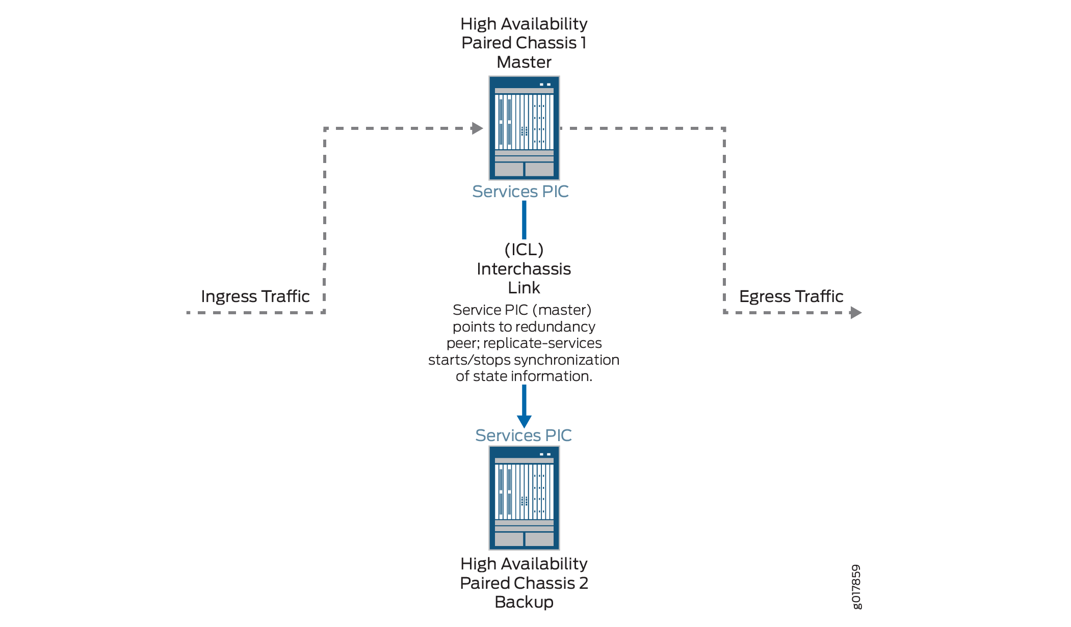
Stateful synchronization replicates the state of long-lived NAT, stateful firewall, and IDS sessions on the primary services PIC and sends it to the backup services PIC, which is on a different MX Series chassis. By default, long lived sessions are defined as having been active on the services PIC for at least 180 seconds, though you can configure this to a higher value.

The following restrictions apply:

  • NAPT44 is the only translation type supported.

Replicating state information for the port block allocation (PBA), endpoint-independent mapping (EIM), or endpoint-independent filters (EIF) features are supported supported for Next Gen Services.

When configuring a service set for NAT, stateful firewall, or IDS that belongs to a stateful synchronization setup, you must use a next-hop service set, and the NAT, stateful firewall, and IDS configurations for the service set must be identical on both MX Series chassis.

Figure 1 shows the stateful synchronization topology.

Figure 1: Stateful Sync TopologyStateful Sync Topology

Benefits

Interchassis stateful synchronization of the services session state allows uninterrupted services when a switchover occurs from a services PIC on one chassis to a services PIC on another chassis.

Configuring Inter-Chassis Stateful Synchronization for Long- Lived NAT, Stateful Firewall, and IDS Flows for Next Gen Services

Configuring Inter-Chassis Stateful Synchronization for Next Gen Services with non-AMS Interface

To configure stateful synchronization inter-chassis high availability for NAT, stateful firewall, and IDS flows for Next Gen Services when the services interfaces are not AMS, perform the following configuration steps on each chassis of the high availability pair.

  1. Specify the IP address of the vms- interface. This address is used by the TCP channel between the HA pairs.
    content_copy zoom_out_map
    [edit interfaces interface-name redundancy-options]
    user@host# set redundancy-local data-address address
    

    For example:

    content_copy zoom_out_map
    [edit interfaces vms-1/0/0 redundancy-options]
    user@host# set redundancy-local data-address 192.0.2.2
    

    When you configure the other chassis, this is the address you use for the redundancy-peer ipaddress.

  2. Specify the IP address of the remote services interface. This address is used by the TCP channel between the HA pairs.
    content_copy zoom_out_map
    [edit interfaces interface-name redundancy-options]
    user@host# set redundancy-peer ipaddress address
    

    For example:

    content_copy zoom_out_map
    [edit interfaces vms-1/0/0 redundancy-options]
    user@host# set redundancy-peer ipaddress 192.0.2.1
    

    When you configure the other chassis, this is the address you use for the redundancy-local data-address.

  3. Configure the length of time that the flow remains active for replication, in seconds.
    content_copy zoom_out_map
    [edit interfaces interface-name redundancy-options]
    user@host# set replication-threshold seconds
    

    For example:

    content_copy zoom_out_map
    [edit interfaces vms-1/0/0 redundancy-options]
    user@host# set replication-threshold 60
    
  4. Configure a unit other than 0, and assign it the IP address of the local services interface that you configured with the redundancy-local data-address option.
    content_copy zoom_out_map
    [edit interfaces interface-name]
    user@host# set unit logical-unit-number family (inet | inet6) address address
    

    For example:

    content_copy zoom_out_map
    [edit interfaces vms-1/0/0]
    user@host# set unit 10 family inet address 192.0.2.2/32
    
  5. For ease of management, we recommend you create a special routing instance with instance-type vrf to host the HA synchronization traffic between the MX Series high availability pair. Then specify the name of the special routing instance to apply to the HA synchronization traffic between the high availability pair.
    content_copy zoom_out_map
    [edit interfaces interface-name redundancy-options]
    user@host# set routing-instance instance-name
    
  6. Configure the inside and outside interface units, which are used by the next-hop service set. Use different unit numbers for the inside and outside units, and do not use 0 or the unit number used in Step 4.
    content_copy zoom_out_map
    [edit]
    user@host# set interfaces interface-name unit logical-unit-number family (inet | inet6)
    user@host# set interfaces interface-name unit logical-unit-number service-domain inside
    user@host# set interfaces interface-name unit logical-unit-number family (inet | inet6)
    user@host# set interfaces interface-name unit logical-unit-number service-domain outside
    

    For example:

    content_copy zoom_out_map
    [edit]
    user@host# set interfaces vms-1/0/0 unit 100 family inet
    user@host# set interfaces vms-1/0/0 unit 100 family inet6
    user@host# set interfaces vms-1/0/0 unit 100 service-domain inside
    user@host# set interfaces vms-1/0/0 unit 1000 family inet
    user@host# set interfaces vms-1/0/0 unit 1000 family inet6
    user@host# set interfaces vms-1/0/0 unit 1000 service-domain outside
    
  7. Configure the next-hop service set that contains the NAT rules, stateful firewall rules, or IDS screens. The service set must be configured identically on each chassis of the high availability pair. The NAT rules, stateful firewall rules, and IDS screens must also be configured identically on each chassis.

    For example:

    content_copy zoom_out_map
    user@host#set service-set internal-nat next-hop-service inside-service-interface vms-1/0/0.100
    user@host#set service-set internal-nat next-hop-service outside-service-interface vms-1/0/0.1000
    user@host#set service-set internal-nat next-hop-service nat-rules internal-nat1
    
  8. Repeat these steps for the other chassis of the high availability pair.

Configuring Inter-Chassis Stateful Synchronization for Next Gen Services with AMS Interface

To configure stateful synchronization inter-chassis high availability for NAT, stateful firewall, and IDS flows for Next Gen Services for an AMS services interface, perform the following configuration steps on each chassis of the high availability pair.

  1. Configure a services vms- interface for every member of the AMS interface:
    1. Specify the IP address of the vms- interface. This address is used by the TCP channel between the HA pairs.
      content_copy zoom_out_map
      [edit interfaces interface-name redundancy-options]
      user@host# set redundancy-local data-address address
      

      For example:

      content_copy zoom_out_map
      [edit interfaces vms-1/0/0 redundancy-options]
      user@host# set redundancy-local data-address 192.0.2.2
      

      When you configure the other chassis, this is the address you use for the redundancy-peer ipaddress.

    2. Specify the IP address of the remote services interface. This address is used by the TCP channel between the HA pairs.
      content_copy zoom_out_map
      [edit interfaces interface-name redundancy-options]
      user@host# set redundancy-peer ipaddress address
      

      For example:

      content_copy zoom_out_map
      [edit interfaces vms-1/0/0 redundancy-options]
      user@host# set redundancy-peer ipaddress 192.0.2.1
      

      When you configure the other chassis, this is the address you use for the redundancy-local data-address.

    3. Configure the length of time that the flow remains active for replication, in seconds.
      content_copy zoom_out_map
      [edit interfaces interface-name redundancy-options]
      user@host# set replication-threshold seconds
      

      For example:

      content_copy zoom_out_map
      [edit interfaces vms-1/0/0 redundancy-options]
      user@host# set replication-threshold 60
      
    4. Configure a unit other than 0, and assign it the IP address of the local services interface that you configured with the redundancy-local data-address option.
      content_copy zoom_out_map
      [edit interfaces interface-name]
      user@host# set unit logical-unit-number family inet address address
      

      For example:

      content_copy zoom_out_map
      [edit interfaces vms-1/0/0]
      user@host# set unit 10 family inet address 192.0.2.2/32
      
    5. For ease of management, we recommend you create a special routing instance with instance-type vrf to host the HA synchronization traffic between the MX Series high availability pair. Then specify the name of the special routing instance to apply to the HA synchronization traffic between the high availability pair.
      content_copy zoom_out_map
      [edit interfaces interface-name redundancy-options]
      user@host# set routing-instance instance-name
      
  2. Create the AMS interface and add the member interfaces you configured in Step 1.
    content_copy zoom_out_map
    [edit interfaces]
    user@host# set interface-name load-balancing-options [member-interface mams-a/b/0]
    

    where the interface-name is amsN, and a is the FPC slot number and b is the PIC slot number for each member interface.

    For example:

    content_copy zoom_out_map
    [edit interfaces]
    user@host# set ams0 load-balancing-options member-interface mams-1/0/0
    user@host# set ams0 load-balancing-options member-interface mams-1/1/0
    
  3. Configure the inside interface for the AMS interface, which is used by the next-hop service set:
    1. Configure the family for the inside interface. Do not use 0 for the unit number.
      content_copy zoom_out_map
      [edit]
      user@host# set interfaces interface-name unit logical-unit-number service-domain inside 
      user@host# set interfaces interface-name unit logical-unit-number family (inet | inet6)
      

      For example:

      content_copy zoom_out_map
      [edit]
      user@host# set interfaces ams0 unit 100 service-domain inside 
      user@host# set interfaces ams0 unit 100 family inet
      user@host# set interfaces ams0 unit 100 family inet6
      
    2. Configure the hash key to regulate distribution for the inside interface.
      content_copy zoom_out_map
      [edit set interfaces interface-name unit logical-unit-number]
      user@host# load-balancing-options hash-keys ingress-key [source-ip destination-ip]
      
  4. Configure the outside interface for the AMS interface, which is used by the next-hop service set. Do not use 0 or the same unit number that you used for the inside interface.

    1. Configure the family for the outside interface.

      content_copy zoom_out_map
      [edit]
      user@host# set interfaces interface-name unit logical-unit-number service-domain outside 
      user@host# set interfaces interface-name unit logical-unit-number family (inet | inet6)
      

      For example:

      content_copy zoom_out_map
      [edit]
      user@host# set interfaces ams0 unit 1000 service-domain outside 
      user@host# set interfaces ams0 unit 1000 family inet
      user@host# set interfaces ams0 unit 1000 family inet6
      
    2. Configure the hash key to regulate distribution for the outside interface.
      content_copy zoom_out_map
      [edit set interfaces interface-name unit logical-unit-number]
      user@host# load-balancing-options hash-keys ingress-key [source-ip destination-ip]
      
  5. Configure the next-hop service set that contains the NAT rules, stateful firewall rules, or IDS screens. The service set must be configured identically on each chassis of the high availability pair. The NAT rules, stateful firewall rule, and IDS screens must also be configured identically on each chassis.

    For example:

    content_copy zoom_out_map
    user@host#set service-set internal-nat next-hop-service inside-service-interface ams0.100
    user@host#set service-set internal-nat next-hop-service outside-service-interface ams0.1000
    user@host#set service-set internal-nat next-hop-service nat-rules internal-nat1
    
  6. Repeat these steps for the other chassis of the high availability pair.
footer-navigation