ON THIS PAGE
Example: Configuring an MX Router as an SAEGW-U
This example shows how to configure an MX Series Router as an SAEGW-U for the Junos Multi-Access User Plane solution.
This example is also valid for configuring an MX Series Router as a UPF for 5G sessions. Junos Multi-Access User Plane can support 4G and 5G sessions simultaneously.
Requirements
This example uses the following hardware and software components:
MX480 (can also be MX240, MX960) router with:
Two MPC7s to act as anchor packet forwarding engines (PFEs) to handle GTP-U processing
Two MPC2s (can also be MPC3, MPC5, MPC7, MPC10) to act as ingress and egress PFEs
-
Junos OS Release 21.3R1 or later
Figure 1 below shows the hardware for this example.
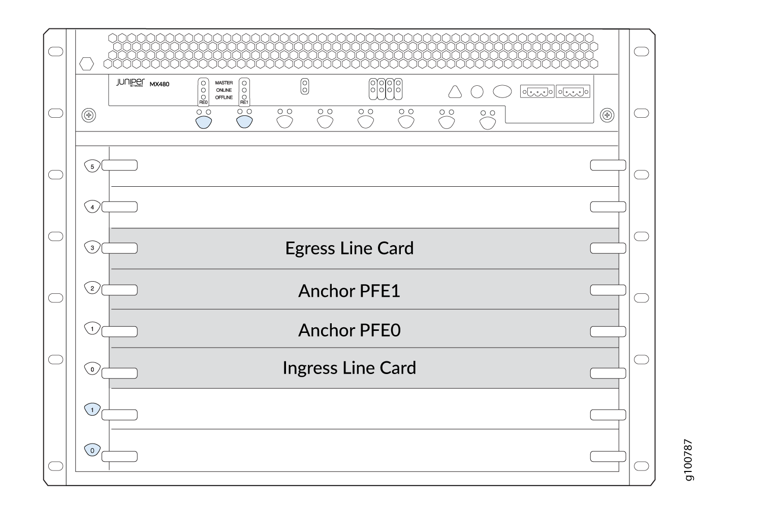
The ingress line card (slot 0) provides the S1-U interface, connecting to the radio access network (RAN), and the combined Sxa/Sxb interface, connecting to the SAEGW-C.
The anchor PFE line cards (slots 1 and 2) provide the core processing of data traffic through internal
pfe-interfaces. At least one anchor PFE card is required, but two are recommended to provide redundancy.The egress line card (slot 3) provides the SGi interface, connecting to the core Internet.
Before you configure the MX Series Router as an SAEGW-U for the Junos Multi-Access User Plane solution, be sure you have:
At least one configured SAEGW-C that you provide
At lease one eNodeB
Access to a packet data network (PDN)
Overview
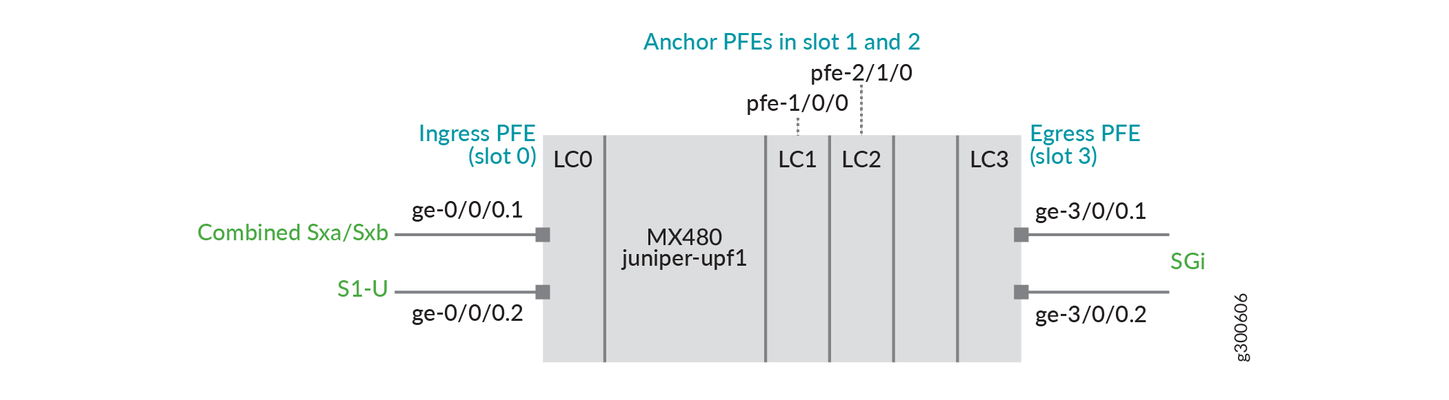
Topology
In this example (see Figure 2):
An MPC2 is in slot 0 with ge-0/0/0.1 providing the combined Sxa/Sxb interface and ge-0/0/0.2 providing the S1-U interface.
MPC7s are in slots 1 and 2 to provide the anchor PFE interfaces.
And MPC2 is in slot 3 with ge-3/0/0.1 and ge-3/0/0.2 providing SGi interfaces.
Configuration
CLI Quick Configuration
To quickly configure this example, copy the following commands, paste them into a text file, remove any line breaks, change any details necessary to match your network configuration, and then copy and paste the commands into the CLI at the [edit] hierarchy level.
set system ddos-protection protocols pfcp aggregate bandwidth 20000
set system ddos-protection protocols pfcp aggregate burst 9000
set system ddos-protection protocols pfcp aggregate recover-time 30
set system ddos-protection protocols gtp-path-mgmt aggregate bandwidth 8400
set system ddos-protection protocols gtp-path-mgmt aggregate burst 8400
set system ddos-protection protocols gtp-path-mgmt aggregate recover-time 30
set chassis redundancy graceful-switchover
set chassis fpc 1 pfe 0 forwarding-packages mobility user-plane
set chassis fpc 2 pfe 1 forwarding-packages mobility user-plane
set chassis network-services enhanced-ip
set interfaces ge-0/0/0 vlan-tagging
set interfaces ge-0/0/0 unit 1 vlan-id 101
set interfaces ge-0/0/0 unit 2 vlan-id 102
set interfaces ge-0/0/0 unit 1 family inet address 10.0.0.1/24
set interfaces ge-0/0/0 unit 2 family inet address 20.0.0.1/24

set interfaces ge-3/0/0 vlan-tagging
set interfaces ge-3/0/0 unit 1 vlan-id 101
set interfaces ge-3/0/0 unit 2 vlan-id 102
set interfaces ge-3/0/0 unit 1 family inet address 30.0.1.1/24
set interfaces ge-3/0/0 unit 2 family inet address 30.0.2.1/24
set interfaces lo0 unit 0 family inet address 100.0.0.1/32
set interfaces mif unit 0 family inet
set interfaces mif unit 1 family inet
set interfaces apfe0 anchoring-options primary-list pfe-1/0/0
set interfaces apfe0 anchoring-options secondary pfe-2/1/0
set services mobile-edge gateways saegw juniper-upf1 control-plane-peers local-address 10.0.0.1
set services mobile-edge gateways saegw juniper-upf1 control-plane-peers path-management enable
set services mobile-edge gateways saegw juniper-upf1 control-plane-peers heartbeat-interval 60
set services mobile-edge gateways saegw juniper-upf1 control-plane-peers apn-services apns apn-default mobile-interface mif.0
set services mobile-edge gateways saegw juniper-upf1 control-plane-peers apn-services apns apn-vrf1 mobile-interface mif.1
set services mobile-edge gateways saegw juniper-upf1 access-network-peers local-address 20.0.0.1
set services mobile-edge gateways saegw juniper-upf1 system anchor-pfes interface apfe0
set routing-instances vrf1 instance-type virtual-router
set routing-instances vrf1 interface mif.1
set routing-instances vrf1 interface ge-3/0/0.2
set routing-instances vrf1 routing-options static route 0.0.0.0/0 next-table inet.0
Procedure
Step-by-Step Procedure
The following example requires you to navigate various levels in the configuration hierarchy. For information about navigating the CLI, see Using the CLI Editor in Configuration Mode.
To configure the MX Router as an SAEGW-U:
-
Enable DDoS attack protection for PFCP protocol traffic.
[edit system ddos-protection protocols]
user@host# set pfcp aggregate bandwidth 20000
user@host# set pfcp aggregate burst 9000
user@host# set pfcp aggregate recover-time 30
user@host# set gtp-path-mgmt aggregate bandwidth 8400
user@host# set gtp-path-mgmt aggregate burst 8400
user@host# set gtp-path-mgmt aggregate recover-time 30
-
Configure Graceful Restart (GRES).
[edit chassis]
user@host# set redundancy graceful-switchover
-
Configure slot 1 & slot 2 for anchor PFE processing.
[edit chassis]
user@host# set fpc 1 pfe 0 forwarding-packages mobility user-plane
user@host# set fpc 2 pfe 1 forwarding-packages mobility user-plane
-
Enable enhanced IP network services.
[edit chassis]
user@host# set network-services enhanced-ip
-
Configure the ingress logical interfaces using vlans.
[edit interfaces ge-0/0/0]
user@host# set vlan-tagging
user@host# set unit 1 vlan-id 101
user@host# set unit 2 vlan-id 102
user@host# set unit 1 family inet address 10.0.0.1/24
user@host# set unit 2 family inet address 20.0.0.1/24
-
Configure the egress PFE for routing to core/ Internet for subscriber in VRF default (apn1).
[edit interfaces ge-3/0/0]
user@host# set vlan-tagging
user@host# set unit 1 vlan-id 101
user@host# set unit 2 vlan-id 102
user@host# set unit 1 family inet address 30.0.1.1/24
user@host# set unit 2 family inet address 30.0.2.1/24
-
Configure the loopback address and the mobile interface for subscriber VRFs.
[edit interfaces lo0]
user@host# set unit 0 family inet address 100.0.0.1/32
[edit interfaces mif]
user@host# set unit 0 family inet
user@host# set unit 1 family inet
-
Define the redundancy anchor PFE interfaces.
[edit interfaces]
user@host# set apfe0 anchoring-options primary-list pfe-1/0/0
user@host# set apfe0 anchoring-options secondary pfe-2/1/0
-
Name the SAEGW-U gateway
juniper-upf1and configure the address where PFCP peers will connect to the SAEGW-U. Also, configure two APNs for SAEGW-U (apn-defaultto place sessions in the default routing instance andapn-vrf1for sessions intoVRF1).[edit services mobile-edge gateways] user@host# set saegw juniper-upf1 control-plane-peers local-address 10.0.0.1 [edit services mobile-edge gateways saegw juniper-upf1 control-plane-peers] user@host# set path-management enable user@host# set heartbeat-interval 60 user@host# set apn-services apns apn-default mobile-interface mif.0 user@host# set apn-services apns apn-vrf1 mobile-interface mif.1
-
Configure the address where GTP-U peers will connect to the SAEGW-U.
Note:This is done at a different command hierarchy from the previous step.
[edit services mobile-edge gateways saegw juniper-upf1 access-network-peers]
user@host# set local-address 20.0.0.1
-
Configure aggregate interface
apfe0for PFCP processing.[edit services mobile-edge gateways saegw juniper-upf1 system] user@host# set anchor-pfes interface apfe0
-
Configure the egress PFE for routing to core/ Internet for subscriber in VRF vrf1 (apn2).
[edit routing-instances vrf1]
user@host# set instance-type virtual-router
user@host# set interface mif.1
user@host# set interface ge-3/0/0.2
user@host# set routing-options static route 0.0.0.0/0 next-table inet.0
Results
From configuration mode, confirm your configuration by entering the show
chassis, show interfaces, show
services, show routing-instances, and show
unified-edge commands. If the output does not display the intended
configuration, repeat the instructions in this example to correct the
configuration.
user@host# show system
ddos-protection {
    protocols {
        gtp-path-mgmt {
            aggregate {
                bandwidth 8400;
                burst 8400;
                recover-time 30;
            }
        }
        pfcp {
            aggregate {
                bandwidth 20000;
                burst 9000;
                recover-time 30;
            }
        }
    }
}user@host# show chassis
redundancy {
graceful-switchover;
}
fpc 1 {
pfe 0 {
forwarding-packages {
mobility {
user-plane;
}
}
}
}
fpc 2 {
pfe 1 {
forwarding-packages {
mobility {
user-plane;
}
}
}
}
network-services {
enhanced-ip;
}user@host# show interfaces
ge-0/0/0 {
vlan-tagging {
unit 1 {
vlan-id 101;
}
unit 2 {
vlan-id 102;
}
}
unit 1 {
family inet {
address 10.0.0.1/24;
}
}
unit 2 {
family inet { address 20.0.0.1/24;
}
}
}
ge-3/0/0 {
vlan-tagging {
unit 1 {
vlan-id 101;
}
unit 2 {
vlan-id 102;
}
}
unit 1 {
family inet {
address 30.0.1.1/24;
}
}
unit 2 {
family inet {
address 30.0.2.1/24;
}
}
}
apfe0 {
anchoring-options {
primary-list {
pfe-1/0/0;
}
secondary pfe-2/1/0;
}
}
lo0 {
unit 0 {
family inet {
address 100.0.0.1/32;
}
}
}
mif {
unit 0 {
family inet;
}
unit 1 {
family inet;
}
}user@host# show services
mobile-edge {
gateways {
saegw juniper-upf1 {
system {
anchor-pfes {
interface apfe0;
}
}
control-plane-peers {
local-address 10.0.0.1;
path-management enable;
heartbeat-interval 60;
apn-services {
apns apn-default {
mobile-interface mif.0;
}
apns apn-vrf1 {
mobile-interface mif.1;
}
}
}
access-network-peers {
local-address 20.0.0.1;
}
}
}
}If you are done configuring the device, enter commit from
configuration mode.
Verification
Use various show commands to verify the SAEGW-U is functioning properly.
Verify SAEGW-U State
Purpose
Verify the SAEGW-U is running and that GRES is enabled.
Action
user@host> show services mobile-edge summary
Graceful-Restart        Enabled
Mastership              Master
State                   Running
Bulk Sync               Synchronized
Verify SAEGW-U Peers
Purpose
Verify the SAEGW-U has connected and is communicating with the SAEGW-Cs (control peers) and eNodeBs (access peers).
Action
user@host> show services mobile-edge peers statistics
Peers Summary:
    Total control peers: 1
    Total access peers:  1
    Total association setup request rejects:  0

Control Peer Statistics:
    IP address:         10.0.0.0
    Hostname:           saegw-c1
    Routing-Instance:   default

    Heartbeat Requests Received:             11
    Heartbeat Responses Sent:                11

    Heartbeat Requests Sent:                 2
    Heartbeat Responses Received:            2

    Association Setup Requests Received:     1
    Association Setup Responses Sent:        1

    Association Release Requests Received:   0
    Association Release Responses Sent:      0

    Session Establishment Requests Received: 30000
    Session Establishment Responses Sent (Accepted):    30000
    Session Establishment Responses Sent (Rejected):    0

    Session Modification Requests Received:             30000
    Session Modification Responses Sent (Accepted):     30000
    Session Modification Responses Sent (Rejected):     0

    Session Deletion Requests Received:                 23169
    Session Deletion Responses Sent (Accepted):         22968
    Session Deletion Responses Sent (Rejected):         0

Access Peer Statistics:
    IP address:         20.0.0.0
    Routing-Instance:   default

    Echo Requests Received:                 0
    Echo Responses Sent:                    0
    Echo Requests Sent:                     0
    Echo Responses Received:                0
Verify SAEGW-U Sessions
Purpose
Verify the SAEGW-U has active data sessions.
Action
user@host> show services mobile-edge sessions summary
Sessions by State:
    SESSION_WAIT: 35
    ESTABLISHED: 18561
    Total: 18596

Bearers by State:
    BEARER_WAIT: 30
    ESTABLISHED: 18561
    Total: 18591
user@host> show services mobile-edge sessions
    Session-address: 23.0.21.163 State: ESTABLISHED Num-bearers: 1
        VRF-ID: 0x0 APN: default
        CPF-peer: 10.0.0.2 Access-peer: 20.0.0.2
        Anchor-PFE: apfe0:pfe-1/0/0 Secondary-anchor-PFE: apfe0:pfe-2/1/0
        Local-SEID: 0x20015a2 Remote-SEID: 0x3cb2

    Session-address: 23.0.47.237 State: ESTABLISHED Num-bearers: 1
        VRF-ID: 0x0 APN: default
        CPF-peer: 10.0.0.2 Access-peer: 20.0.0.2
        Anchor-PFE: apfe0:pfe-1/0/0 Secondary-anchor-PFE: apfe0:pfe-2/1/0
        Local-SEID: 0x2fec Remote-SEID: 0x56fc

    Session-address: 23.0.21.49 State: ESTABLISHED Num-bearers: 1
        VRF-ID: 0x0 APN: default
        CPF-peer: 10.0.0.2 Access-peer: 20.0.0.2
        Anchor-PFE: apfe0:pfe-1/0/0 Secondary-anchor-PFE: apfe0:pfe-2/1/0
        Local-SEID: 0x1531 Remote-SEID: 0x3c40

    Session-address: 23.0.29.83 State: ESTABLISHED Num-bearers: 1
        VRF-ID: 0x0 APN: default
        CPF-peer: 10.0.0.2 Access-peer: 20.0.0.2
        Anchor-PFE: apfe0:pfe-1/0/0 Secondary-anchor-PFE: apfe0:pfe-2/1/0
        Local-SEID: 0x2001d53 Remote-SEID: 0x4462

....Change History Table
Feature support is determined by the platform and release you are using. Use Feature Explorer to determine if a feature is supported on your platform.