Policy-Based IPsec VPNs
A policy-based VPN is a configuration in which an IPsec VPN tunnel created between two end points is specified within the policy itself with a policy action for the transit traffic that meets the policy’s match criteria.
Understanding Policy-Based IPsec VPNs
For policy-based IPsec VPNs, a security policy specifies as its action the VPN tunnel to be used for transit traffic that meets the policy’s match criteria. A VPN is configured independent of a policy statement. The policy statement refers to the VPN by name to specify the traffic that is allowed access to the tunnel. For policy-based VPNs, each policy creates an individual IPsec security association (SA) with the remote peer, each of which counts as an individual VPN tunnel. For example, if a policy contains a group source address and a group destination address, whenever one of the users belonging to the address set attempts to communicate with any one of the hosts specified as the destination address, a new tunnel is negotiated and established. Because each tunnel requires its own negotiation process and separate pair of SAs, the use of policy-based IPsec VPNs can be more resource-intensive than route-based VPNs.
Examples of where policy-based VPNs can be used:
You are implementing a dial-up VPN.
Policy-based VPNs allow you to direct traffic based on firewall policies.
We recommend that you use route-based VPN when you want to configure a VPN between multiple remote sites. Route-based VPNs can provide the same capabilities as policy-based VPNs.
Limitations:
-
Policy-based IPSec VPNs are not supported with IKEv2.
-
Support for policy-based IPsec VPN is not available when using
junos-ikepackage with your firewall runningikedprocess for IPsec VPN service. Withjunos-ikepackage, remove any policy-based IPsec VPN configurations as they are ineffective. Note that in SRX5K-SPC3 with RE3, thejunos-ikepackage is available by default. In platforms SRX1500 and higher, it’s an optional package. See IPsec VPN Feature Support with New Package for more details.
See Also
Example: Configuring a Policy-Based VPN
This example shows how to configure a policy-based IPsec VPN to allow data to be securely transferred between two sites.
Requirements
This example uses the following hardware:
-
Any SRX Series Firewall
- Updated and revalidated using vSRX Virtual Firewall on Junos OS Release 20.4R1.
Are you interested in getting hands-on experience with the topics and operations covered in this guide? Visit the IPsec Policy-Based demonstration in Juniper Networks Virtual Labs and reserve your free sandbox today! You’ll find the IPsec VPN Policy-Based sandbox in the Security category.
Before you begin, read IPsec Overview.
Overview
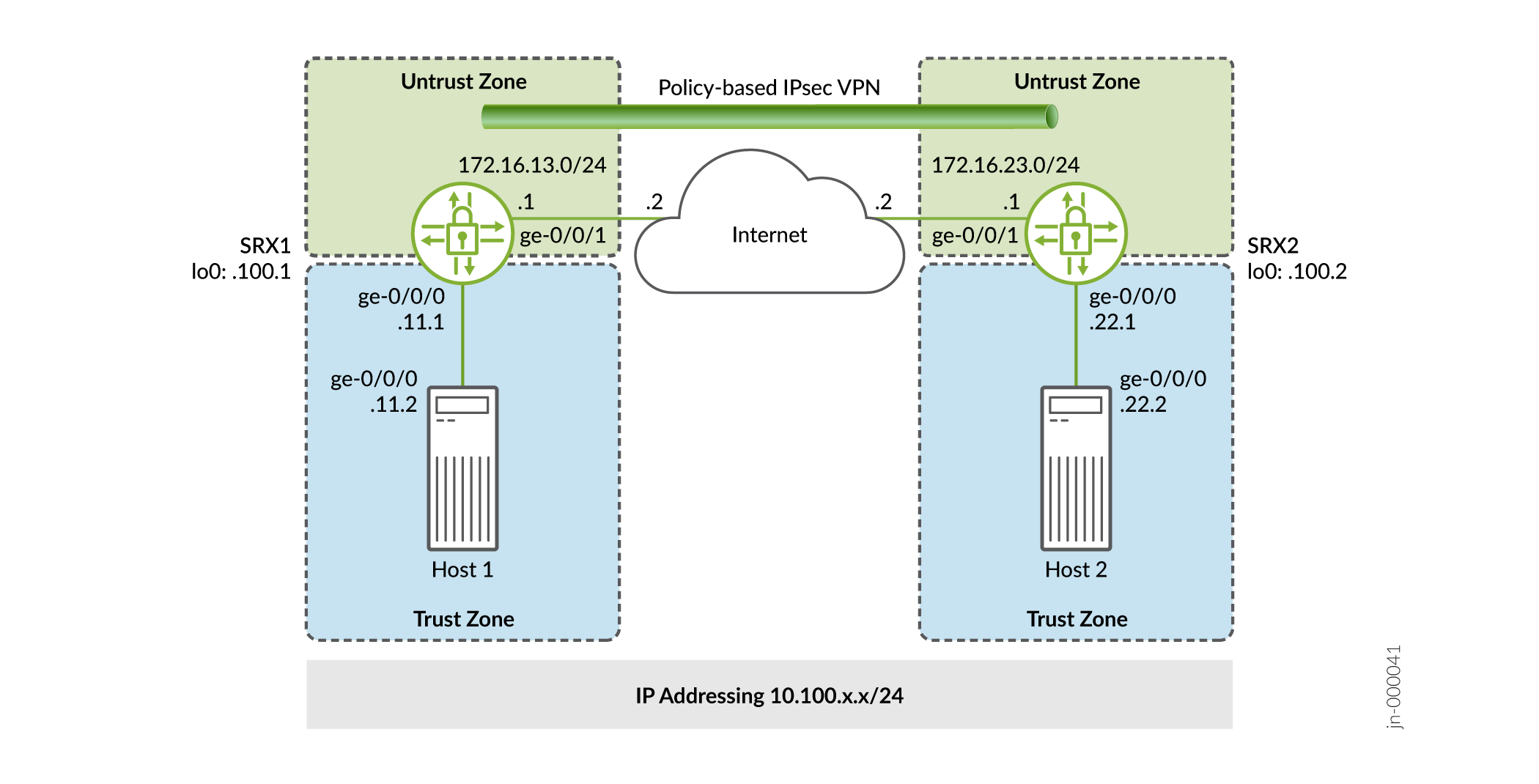
In this example, you configure a policy-based VPN on SRX1 and SRX2. Host1 and Host2 use the VPN to send traffic securely over the Internet between both hosts.
Figure 1 shows an example of a policy-based VPN topology.
IKE IPsec tunnel negotiation occurs in two phases. In Phase 1, participants establish a secure channel in which to negotiate the IPsec security association (SA). In Phase 2, participants negotiate the IPsec SA for authenticating traffic that will flow through the tunnel. Just as there are two phases to tunnel negotiation, there are two phases to tunnel configuration.
In this example, you configure interfaces, an IPv4 default route, and security zones. Then you configure IKE Phase 1, IPsec Phase 2, security policy, and TCP-MSS parameters. See Table 1 through Table 5.
|
Feature |
Name |
Configuration Parameters |
|---|---|---|
|
Interfaces |
ge-0/0/0.0 |
10.100.11.1/24 |
|
ge-0/0/1.0 |
172.16.13.1/24 |
|
|
Security zones |
trust |
|
|
untrust |
|
|
|
Static routes |
0.0.0.0/0 |
|
|
Feature |
Name |
Configuration Parameters |
|---|---|---|
|
Proposal |
standard |
|
|
Policy |
IKE-POL |
|
|
Gateway |
IKE-GW |
|
|
Feature |
Name |
Configuration Parameters |
|---|---|---|
|
Proposal |
standard |
|
|
Policy |
IPSEC-POL |
|
|
VPN |
VPN-to-Host2 |
|
|
Purpose |
Name |
Configuration Parameters |
|---|---|---|
|
This security policy permits traffic from the trust zone to the untrust zone. |
VPN-OUT |
|
|
This security policy permits traffic from the untrust zone to the trust zone. |
VPN-IN |
|
|
This security policy permits all traffic from the trust zone to the untrust zone. You must put the VPN-OUT policy before the default-permit security policy. Junos OS performs a security policy lookup starting at the top of the list. If the default-permit policy comes before the VPN-OUT policy, all traffic from the trust zone matches the default-permit policy and is permitted. Thus, no traffic will ever match the VPN-OUT policy. |
default-permit |
|
|
Purpose |
Configuration Parameters |
|---|---|
|
TCP-MSS is negotiated as part of the TCP three-way handshake and limits the maximum size of a TCP segment to better fit the maximum transmission unit (MTU) limits on a network. This is especially important for VPN traffic, as the IPsec encapsulation overhead, along with the IP and frame overhead, can cause the resulting Encapsulating Security Payload (ESP) packet to exceed the MTU of the physical interface, thus causing fragmentation. Fragmentation results in increased use of bandwidth and device resources. We recommend a value of 1350 as the starting point for most Ethernet-based networks with an MTU of 1500 or greater. You might need to experiment with different TCP-MSS values to obtain optimal performance. For example, you might need to change the value if any device in the path has a lower MTU, or if there is any additional overhead such as PPP or Frame Relay. |
MSS value: 1350 |
Configuration
- Configuring Basic Network and Security Zone Information
- Configuring IKE
- Configuring IPsec
- Configuring Security Policies
- Configuring TCP-MSS
- Configuring SRX2
Configuring Basic Network and Security Zone Information
CLI Quick Configuration
To quickly configure this example for SRX1, copy the following commands,
paste them into a text file, remove any line breaks, change any details
necessary to match your network configuration, copy and paste the commands
into the CLI at the [edit] hierarchy level, and then enter
commit from configuration mode.
set interfaces ge-0/0/0 unit 0 family inet address 10.100.11.1/24
set interfaces ge-0/0/1 unit 0 family inet address 172.16.13.1/24
set interfaces lo0 unit 0 family inet address 10.100.100.1/32
set routing-options static route 0.0.0.0/0 next-hop 172.16.13.2
set security zones security-zone trust host-inbound-traffic system-services all
set security zones security-zone trust interfaces ge-0/0/0.0
set security zones security-zone untrust host-inbound-traffic system-services ike
set security zones security-zone untrust host-inbound-traffic system-services ping
set security zones security-zone untrust interfaces ge-0/0/1.0
Step-by-Step Procedure
The following example requires you to navigate various levels in the configuration hierarchy. For instructions on how to do this, see the CLI User Guide.
To configure interface, static route, and security zone information:
-
Configure the interfaces.
[edit]
user@SRX1# set interfaces ge-0/0/0 unit 0 family inet address 10.100.11.1/24
user@SRX1# set interfaces ge-0/0/1 unit 0 family inet address 172.16.13.1/24
user@SRX1# set interfaces lo0 unit 0 family inet address 10.100.100.1/32
-
Configure the static routes.
[edit]
user@SRX1# set routing-options static route 0.0.0.0/0 next-hop 172.16.13.2
-
Assign the Internet facing interface to the untrust security zone.
[edit security zones security-zone untrust]
user@SRX1# set interfaces ge-0/0/1.0
-
Specify the allowed system services for the untrust security zone.
[edit security zones security-zone untrust]
user@SRX1# set host-inbound-traffic system-services ike
user@SRX1# set host-inbound-traffic system-services ping
-
Assign the Host1 facing interface to the trust security zone.
[edit security zones security-zone trust]
user@SRX1# set interfaces ge-0/0/0.0
-
Specify the allowed system services for the trust security zone.
[edit security zones security-zone trust]
user@SRX1# set host-inbound-traffic system-services all
Results
From configuration mode, confirm your configuration by entering the
show interfaces, show routing-options,
and show security zones commands. If the output does not
display the intended configuration, repeat the configuration instructions in
this example to correct it.
[edit]
user@SRX1# show interfaces
ge-0/0/0 {
    unit 0 {
        family inet {
            address 10.100.11.1/24;
        }
    }
}
ge-0/0/1 {
    unit 0 {
        family inet {
            address 172.16.13.1/24;
        }
    }
}
lo0 {
    unit 0 {
        family inet {
            address 10.100.100.1/32;
        }
    }
}
[edit]
user@SRX1# show routing-options
static {
    route 0.0.0.0/0 next-hop 172.16.13.2;
}
[edit]
user@SRX1# show security zones
security-zone trust {
    host-inbound-traffic {
        system-services {
            all;
        }
    }
    interfaces {
        ge-0/0/0.0;
    }
}
security-zone untrust {
    host-inbound-traffic {
        system-services {
            ike;
            ping;
        }
    }
    interfaces {
        ge-0/0/1.0;
    }
}
Configuring IKE
CLI Quick Configuration
To quickly configure this example for SRX1, copy the following commands,
paste them into a text file, remove any line breaks, change any details
necessary to match your network configuration, copy and paste the commands
into the CLI at the [edit] hierarchy level, and then enter
commit from configuration mode.
set security ike proposal standard authentication-method pre-shared-keys
set security ike policy IKE-POL mode main
set security ike policy IKE-POL proposals standard
set security ike policy IKE-POL pre-shared-key ascii-text $ABC123
set security ike gateway IKE-GW ike-policy IKE-POL
set security ike gateway IKE-GW address 172.16.23.1
set security ike gateway IKE-GW external-interface ge-0/0/1
Step-by-Step Procedure
The following example requires you to navigate various levels in the configuration hierarchy. For instructions on how to do that, see the CLI User Guide.
To configure IKE:
-
Create the IKE proposal.
[edit security ike]
user@SRX1# set proposal standard
-
Define the IKE proposal authentication method.
[edit security ike proposal standard]
user@SRX1# set authentication-method pre-shared-keys
-
Create the IKE policy.
[edit security ike]
user@SRX1# set policy IKE-POL
-
Set the IKE policy mode.
[edit security ike policy IKE-POL]
user@SRX1# set mode main
-
Specify a reference to the IKE proposal.
[edit security ike policy IKE-POL]
user@SRX1# set proposals standard
-
Define the IKE policy authentication method.
[edit security ike policy IKE-POL]
user@SRX1# set pre-shared-key ascii-text $ABC123
-
Create the IKE gateway and define its external interface.
[edit security ike gateway IKE-GW]
user@SRX1# set external-interface ge-0/0/1.0
-
Define the IKE gateway address.
[edit security ike gateway IKE-GW]
user@SRX1# address 172.16.23.1
-
Define the IKE policy reference.
[edit security ike gateway IKE-GW]
user@SRX1# set ike-policy IKE-POL
Results
From configuration mode, confirm your configuration by entering the
show security ike command. If the output does not
display the intended configuration, repeat the configuration instructions in
this example to correct it.
[edit]
user@host# show security ike
proposal standard {
    authentication-method pre-shared-keys;
}
policy IKE-POL {
    mode main;
    proposals standard;
    pre-shared-key ascii-text "$ABC123"; ## SECRET-DATA
}
gateway IKE-GW {
    ike-policy IKE-POL;
    address 172.16.23.1;
    external-interface ge-0/0/1;
}
Configuring IPsec
CLI Quick Configuration
To quickly configure this example for SRX1, copy the following commands,
paste them into a text file, remove any line breaks, change any details
necessary to match your network configuration, copy and paste the commands
into the CLI at the [edit] hierarchy level, and then enter
commit from configuration mode.
set security ipsec proposal standard
set security ipsec policy IPSEC-POL proposals standard
set security ipsec vpn VPN-to-Host2 ike gateway IKE-GW
set security ipsec vpn VPN-to-Host2 ike ipsec-policy IPSEC-POL
set security ipsec vpn VPN-to-Host2 establish-tunnels immediately
Step-by-Step Procedure
The following example requires you to navigate various levels in the configuration hierarchy. For instructions on how to do that, see the CLI User Guide.
To configure IPsec:
-
Create the IPsec proposal.
[edit]
user@SRX1# set security ipsec proposal standard
-
Create the IPsec policy.
[edit security ipsec]
user@SRX1# set policy IPSEC-POL
-
Specify the IPsec proposal reference.
[edit security ipsec policy IPSEC-POL]
user@SRX1# set proposals standard
-
Specify the IKE gateway.
[edit security ipsec]
user@SRX1# set vpn VPN-to-Host2 ike gateway IKE-GW
-
Specify the IPsec policy.
[edit security ipsec]
user@SRX1# set vpn VPN-to-Host2 ike ipsec-policy IPSEC-POL
-
Configure the tunnel to establish immediately.
[edit security ipsec]
user@SRX1# set vpn VPN-to-Host2 establish-tunnels immediately
Results
From configuration mode, confirm your configuration by entering the
show security ipsec command. If the output does not
display the intended configuration, repeat the configuration instructions in
this example to correct it.
[edit]
user@SRX1# show security ipsec
proposal standard;
policy IPSEC-POL {
    proposals standard;
}
vpn VPN-to-Host2 {
    ike {
        gateway IKE-GW;
        ipsec-policy IPSEC-POL;
    }
    establish-tunnels immediately;
}
Configuring Security Policies
CLI Quick Configuration
To quickly configure this example for SRX1, copy the following commands,
paste them into a text file, remove any line breaks, change any details
necessary to match your network configuration, copy and paste the commands
into the CLI at the [edit] hierarchy level, and then enter
commit from configuration mode.
set security address-book Host1 address Host1-Net 10.100.11.0/24
set security address-book Host1 attach zone trust
set security address-book Host2 address Host2-Net 10.100.22.0/24
set security address-book Host2 attach zone untrust
set security policies from-zone trust to-zone untrust policy VPN-OUT match source-address Host1-Net
set security policies from-zone trust to-zone untrust policy VPN-OUT match destination-address Host2-Net
set security policies from-zone trust to-zone untrust policy VPN-OUT match application any
set security policies from-zone trust to-zone untrust policy VPN-OUT then permit tunnel ipsec-vpn VPN-to-Host2
set security policies from-zone trust to-zone untrust policy default-permit match source-address any
set security policies from-zone trust to-zone untrust policy default-permit match destination-address any
set security policies from-zone trust to-zone untrust policy default-permit match application any
set security policies from-zone trust to-zone untrust policy default-permit then permit
set security policies from-zone untrust to-zone trust policy VPN-IN match source-address Host2-Net
set security policies from-zone untrust to-zone trust policy VPN-IN match destination-address Host1-Net
set security policies from-zone untrust to-zone trust policy VPN-IN match application any
set security policies from-zone untrust to-zone trust policy VPN-IN then permit tunnel ipsec-vpn VPN-to-Host2
Step-by-Step Procedure
The following example requires you to navigate various levels in the configuration hierarchy. For instructions on how to do that, see the CLI User Guide.
To configure security policies:
-
Create address book entries for the networks that will be used in the security policies.
[edit]
user@SRX1# set security address-book Host1 address Host1-Net 10.100.11.0/24
user@SRX1# set security address-book Host1 attach zone trust
user@SRX1# set security address-book Host2 address Host2-Net 10.100.22.0/24
user@SRX1# set security address-book Host2 attach zone untrust
-
Create the security policy to match on traffic from Host1 in the trust zone to Host2 in the untrust zone.
[edit security policies from-zone trust to-zone untrust]
user@SRX1# set policy VPN-OUT match source-address Host1-Net
user@SRX1# set policy VPN-OUT match destination-address Host2-Net
user@SRX1# set policy VPN-OUT match application any
user@SRX1# set policy VPN-OUT then permit tunnel ipsec-vpn VPN-to-Host2
-
Create the security policy to permit all other traffic to the Internet from the trust zone to the untrust zone.
[edit security policies from-zone trust to-zone untrust]
user@SRX1# set policy default-permit match source-address any
user@SRX1# set policy default-permit match destination-address any
user@SRX1# set policy default-permit match application any
user@SRX1# set policy default-permit then permit
-
Create a security policy to permit traffic from Host2 in the untrust zone to Host1 in the trust zone.
[edit security policies from-zone untrust to-zone trust]
user@SRX1# set policy VPN-IN match source-address Host2-Net
user@SRX1# set policy VPN-IN match destination-address Host1-Net
user@SRX1# set policy VPN-IN match application any
user@SRX1# set policy VPN-IN then permit tunnel ipsec-vpn VPN-to-Host2
Results
From configuration mode, confirm your configuration by entering the
show security policies command. If the output does not
display the intended configuration, repeat the configuration instructions in
this example to correct it.
[edit]
user@SRX1# show security policies
from-zone trust to-zone untrust {
    policy VPN-OUT {
        match {
            source-address Host1-Net;
            destination-address Host2-Net;
            application any;
        }
        then {
            permit {
                tunnel {
                    ipsec-vpn VPN-to-Host2;
                }
            }
        }
    }
    policy default-permit {
        match {
            source-address any;
            destination-address any;
            application any;
        }
        then {
            permit;
        }
    }
}
from-zone untrust to-zone trust {
    policy VPN-IN {
        match {
            source-address Host2-Net;
            destination-address Host1-Net;
            application any;
        }
        then {
            permit {
                tunnel {
                    ipsec-vpn VPN-to-Host2;
                }
            }
        }
    }
}
Configuring TCP-MSS
CLI Quick Configuration
To quickly configure this example for SRX1, copy the following commands,
paste them into a text file, remove any line breaks, change any details
necessary to match your network configuration, copy and paste the commands
into the CLI at the [edit] hierarchy level, and then enter
commit from configuration mode.
set security flow tcp-mss ipsec-vpn mss 1350
Step-by-Step Procedure
To configure TCP-MSS information:
-
Configure the TCP-MSS information.
[edit]
user@SRX1# set security flow tcp-mss ipsec-vpn mss 1350
Results
From configuration mode, confirm your configuration by entering the
show security flow command. If the output does not
display the intended configuration, repeat the configuration instructions in
this example to correct it.
[edit]
user@SRX1# show security flow
tcp-mss {
    ipsec-vpn {
        mss 1350;
    }
}
If you are done configuring the device, enter commit from
configuration mode.
Configuring SRX2
CLI Quick Configuration
For reference, the configuration for SRX2 is provided.
To quickly configure this section of the example, copy the following
commands, paste them into a text file, remove any line breaks, change any
details necessary to match your network configuration, copy and paste the
commands into the CLI at the [edit] hierarchy level, and
then enter commit from configuration mode.
set security ike proposal standard authentication-method pre-shared-keys
set security ike policy IKE-POL mode main
set security ike policy IKE-POL proposals standard
set security ike policy IKE-POL pre-shared-key ascii-text $ABC123
set security ike gateway IKE-GW ike-policy IKE-POL
set security ike gateway IKE-GW address 172.16.13.1
set security ike gateway IKE-GW external-interface ge-0/0/1
set security ipsec proposal standard
set security ipsec policy IPSEC-POL proposals standard
set security ipsec vpn VPN-to-Host1 ike gateway IKE-GW
set security ipsec vpn VPN-to-Host1 ike ipsec-policy IPSEC-POL
set security ipsec vpn VPN-to-Host1 establish-tunnels immediately
set security address-book Host1 address Host1-Net 10.100.11.0/24
set security address-book Host1 attach zone untrust
set security address-book Host2 address Host2-Net 10.100.22.0/24
set security address-book Host2 attach zone trust
set security flow tcp-mss ipsec-vpn mss 1350
set security policies from-zone trust to-zone untrust policy VPN-OUT match source-address Host2-Net
set security policies from-zone trust to-zone untrust policy VPN-OUT match destination-address Host1-Net
set security policies from-zone trust to-zone untrust policy VPN-OUT match application any
set security policies from-zone trust to-zone untrust policy VPN-OUT then permit tunnel ipsec-vpn VPN-to-Host1
set security policies from-zone trust to-zone untrust policy default-permit match source-address any
set security policies from-zone trust to-zone untrust policy default-permit match destination-address any
set security policies from-zone trust to-zone untrust policy default-permit match application any
set security policies from-zone trust to-zone untrust policy default-permit then permit
set security policies from-zone untrust to-zone trust policy VPN-IN match source-address Host1-Net
set security policies from-zone untrust to-zone trust policy VPN-IN match destination-address Host2-Net
set security policies from-zone untrust to-zone trust policy VPN-IN match application any
set security policies from-zone untrust to-zone trust policy VPN-IN then permit tunnel ipsec-vpn VPN-to-Host1
set security zones security-zone trust host-inbound-traffic system-services all
set security zones security-zone trust interfaces ge-0/0/0.0
set security zones security-zone untrust host-inbound-traffic system-services ike
set security zones security-zone untrust host-inbound-traffic system-services ping
set security zones security-zone untrust interfaces ge-0/0/1.0
set interfaces ge-0/0/0 unit 0 family inet address 10.100.22.1/24
set interfaces ge-0/0/1 unit 0 family inet address 172.16.23.1/24
set interfaces lo0 unit 0 family inet address 10.100.100.2/32
set routing-options static route 0.0.0.0/0 next-hop 172.16.23.2
Verification
To confirm that the configuration is working properly, perform these tasks:
- Verifying the IKE Status
- Verifying the IPsec Phase 2 Status
- Test Traffic Flow Across the VPN
- Reviewing Statistics and Errors for an IPsec Security Association
Verifying the IKE Status
Purpose
Verify the IKE status.
Action
From operational mode, enter the show security ike
security-associations command. After obtaining an index number
from the command, use the show security ike security-associations
index index_number detail command.
user@SRX1> show security ike security-associations Index State Initiator cookie Responder cookie Mode Remote Address 1859361 UP 9788fa59c3ee2e2a 0b17e52f34b83aba Main 172.16.23.1
user@SRX1> show security ike security-associations index 1859361 detail
IKE peer 172.16.23.1, Index 1859361, Gateway Name: IKE-GW
Role: Responder, State: UP
Initiator cookie: 9788fa59c3ee2e2a, Responder cookie: 0b17e52f34b83aba
Exchange type: Main, Authentication method: Pre-shared-keys
Local: 172.16.13.1:500, Remote: 172.16.23.1:500
Lifetime: Expires in 17567 seconds
Reauth Lifetime: Disabled
IKE Fragmentation: Disabled, Size: 0
Remote Access Client Info: Unknown Client
Peer ike-id: 172.16.23.1
AAA assigned IP: 0.0.0.0
Algorithms:
Authentication : hmac-sha1-96
Encryption : 3des-cbc
Pseudo random function: hmac-sha1
Diffie-Hellman group : DH-group-2
Traffic statistics:
Input bytes : 1740
Output bytes : 1132
Input packets: 15
Output packets: 7
Input fragmentated packets: 0
Output fragmentated packets: 0
IPSec security associations: 4 created, 4 deleted
Phase 2 negotiations in progress: 1
Negotiation type: Quick mode, Role: Responder, Message ID: 0
Local: 172.16.13.1:500, Remote: 172.16.23.1:500
Local identity: 172.16.13.1
Remote identity: 172.16.23.1
Flags: IKE SA is created
Meaning
The show security ike security-associations command lists
all active IKE Phase 1 security associations (SAs). If no SAs are listed,
there was a problem with Phase 1 establishment. Check the IKE policy
parameters and external interface settings in your configuration.
If SAs are listed, review the following information:
-
Index—This value is unique for each IKE SA, which you can use in the
show security ike security-associations index detailcommand to get more information about the SA. -
Remote Address—Verify that the remote IP address is correct.
-
State
-
UP—The Phase 1 SA has been established.
-
DOWN—There was a problem establishing the Phase 1 SA.
-
-
Mode—Verify that the correct mode is being used.
Verify that the following are correct in your configuration:
-
External interfaces (the interface must be the one that receives IKE packets)
-
IKE policy parameters
-
Preshared key information
-
Phase 1 proposal parameters (must match on both peers)
The show security ike security-associations index 1859361
detail command lists additional information about the security
association with an index number of 1859361:
-
Authentication and encryption algorithms used
-
Phase 1 lifetime
-
Traffic statistics (can be used to verify that traffic is flowing properly in both directions)
-
Initiator and responder role information
Troubleshooting is best performed on the peer using the responder role.
-
Number of IPsec SAs created
-
Number of Phase 2 negotiations in progress
Verifying the IPsec Phase 2 Status
Purpose
Verify the IPsec Phase 2 status.
Action
From operational mode, enter the show security ipsec
security-associations command. After obtaining an index number
from the command, use the show security ipsec security-associations
index index_number detail command.
user@SRX1 show security ipsec security-associations Total active tunnels: 1 Total Ipsec sas: 1 ID Algorithm SPI Life:sec/kb Mon lsys Port Gateway <2 ESP:3des/sha1 ae5afc5a 921/ unlim - root 500 172.16.23.1 >2 ESP:3des/sha1 6388a743 921/ unlim - root 500 172.16.23.1
user@SRX1> show security ipsec security-associations index 2 detail
ID: 2 Virtual-system: root, VPN Name: VPN-to-Host2
Local Gateway: 172.16.13.1, Remote Gateway: 172.16.23.1
Local Identity: ipv4_subnet(any:0,[0..7]=10.100.11.0/24)
Remote Identity: ipv4_subnet(any:0,[0..7]=10.100.22.0/24)
Version: IKEv1
DF-bit: clear, Copy-Outer-DSCP Disabled , Policy-name: VPN-OUT
Port: 500, Nego#: 30, Fail#: 0, Def-Del#: 0 Flag: 0x600829
Multi-sa, Configured SAs# 1, Negotiated SAs#: 1
Tunnel events:
Thu Jul 29 2021 14:29:22 -0700: IPSec SA negotiation successfully completed (29 times)
Thu Jul 29 2021 12:00:30 -0700: IKE SA negotiation successfully completed (4 times)
Wed Jul 28 2021 15:20:58
: IPSec SA delete payload received from peer, corresponding IPSec SAs cleared (1 times)
Wed Jul 28 2021 15:05:13 -0700: IPSec SA negotiation successfully completed (1 times)
Wed Jul 28 2021 15:05:13
: Tunnel is ready. Waiting for trigger event or peer to trigger negotiation (1 times)
Wed Jul 28 2021 15:05:13 -0700: External interface's address received. Information updated (1 times)
Wed Jul 28 2021 15:05:13 -0700: External interface's zone received. Information updated (1 times)
Wed Jul 28 2021 11:17:38
: Negotiation failed with error code NO_PROPOSAL_CHOSEN received from peer (1 times)
Wed Jul 28 2021 09:27:11 -0700: IKE SA negotiation successfully completed (19 times)
Thu Jul 22 2021 16:34:17 -0700: Negotiation failed with INVALID_SYNTAX error (3 times)
Thu Jul 22 2021 10:34:55 -0700: IKE SA negotiation successfully completed (1 times)
Thu Jul 22 2021 10:34:46 -0700: No response from peer. Negotiation failed (16 times)
Direction: inbound, SPI: ae5afc5a, AUX-SPI: 0
, VPN Monitoring: -
Hard lifetime: Expires in 828 seconds
Lifesize Remaining: Unlimited
Soft lifetime: Expires in 234 seconds
Mode: Tunnel(0 0), Type: dynamic, State: installed
Protocol: ESP, Authentication: hmac-sha1-96, Encryption: 3des-cbc
Anti-replay service: counter-based enabled, Replay window size: 64
Direction: outbound, SPI: 6388a743, AUX-SPI: 0
, VPN Monitoring: -
Hard lifetime: Expires in 828 seconds
Lifesize Remaining: Unlimited
Soft lifetime: Expires in 234 seconds
Mode: Tunnel(0 0), Type: dynamic, State: installed
Protocol: ESP, Authentication: hmac-sha1-96, Encryption: 3des-cbc
Anti-replay service: counter-based enabled, Replay window size: 64
Meaning
The output from the show security ipsec
security-associations command lists the following
information:
-
The ID number is 2. Use this value with the
show security ipsec security-associations indexcommand to get more information about this particular SA. -
There is one IPsec SA pair using port 500, which indicates that no NAT-traversal is implemented. (NAT-traversal uses port 4500 or another random high-number port.)
-
The SPIs, lifetime (in seconds), and usage limits (or lifesize in KB) are shown for both directions. The 921/ unlim value indicates that the Phase 2 lifetime expires in 921 seconds, and that no lifesize has been specified, which indicates that it is unlimited. Phase 2 lifetime can differ from Phase 1 lifetime, as Phase 2 is not dependent on Phase 1 after the VPN is up.
-
VPN monitoring is not enabled for this SA, as indicated by a hyphen in the Mon column. If VPN monitoring is enabled, U (up) or D (down) is listed.
-
The virtual system (vsys) is the root system, and it always lists 0.
The output from the show security ipsec security-associations index 2
detail command lists the following information:
-
The local identity and remote identity make up the proxy ID for the SA.
A proxy ID mismatch is one of the most common reasons for a Phase 2 failure. For policy-based VPNs, the proxy ID is derived from the security policy. The local address and remote address are derived from the address book entries, and the service is derived from the application configured for the policy. If Phase 2 fails because of a proxy ID mismatch, you can use the policy to confirm which address book entries are configured. Verify that the addresses match the information being sent. Check the service to ensure that the ports match the information being sent.
Test Traffic Flow Across the VPN
Purpose
Verify the traffic flow across the VPN.
Action
Use the ping command from the Host1 device to test traffic
flow to Host2.
user@Host1> ping 10.100.22.1 rapid count 100
PING 10.100.22.1 (10.100.22.1): 56 data bytes
!!!!!!!!!!!!!!!!!!!!!!!!!!!!!!!!!!!!!!!!!!!!!!!!!!!!!!!!!!!!!!!!!!!!!!!!!!!!!!!!!!!!!!!!!!!!!!!!!!!!
--- 10.100.22.1 ping statistics ---
100 packets transmitted, 100 packets received, 0% packet loss
round-trip min/avg/max/stddev = 3.300/3.936/8.562/0.720 ms
Meaning
If the ping command fails from Host1, there might be a
problem with the routing, security policies, end host, or encryption and
decryption of ESP packets.
Reviewing Statistics and Errors for an IPsec Security Association
Purpose
Review ESP and authentication header counters and errors for an IPsec security association.
Action
From operational mode, enter the show security ipsec statistics index
index_number command, using the index
number of the VPN for which you want to see statistics.
user@SRX1> show security ipsec statistics index 2
ESP Statistics:
  Encrypted bytes:            13600
  Decrypted bytes:             8400
  Encrypted packets:            100
  Decrypted packets:            100
AH Statistics:
  Input bytes:                    0
  Output bytes:                   0
  Input packets:                  0
  Output packets:                 0
Errors:
  AH authentication failures: 0, Replay errors: 0
  ESP authentication failures: 0, ESP decryption failures: 0
  Bad headers: 0, Bad trailers: 0
You can also use the show security ipsec statistics command
to review statistics and errors for all SAs.
To clear all IPsec statistics, use the clear security ipsec
statistics command.
Meaning
If you see packet loss issues across a VPN, you can run the show
security ipsec statistics command several times to confirm that
the encrypted and decrypted packet counters are incrementing. You should
also check if the other error counters are incrementing.
Migrate Policy-Based VPNs to Route-Based VPNs
Read this topic if you plan to migrate your configuration from policy-based VPNs to route-based VPNs using the shared point-to-point st0 interface.
Although the SRX Series Firewalls support policy-based VPNs on firewalls that run the IPsec VPN using the kmd process, there are associated limitations. While the policy can control the traffic entering the VPN tunnel in terms of the protocol and the port number of an application, IKEv1 doesn't support protocol or port negotiation in security association (SA) negotiation. So the firewall cannot perform granular control of traffic with policy-based VPNs. We recommend that you migrate your policy-based VPNs to route-based VPNs.
To migrate from policy-based VPNs to route-based VPNs, perform the following steps:
-
Deactivate the IPsec VPN objects that are running in your Junos OS device using the kmd process.
-
Install the
junos-ikepackage to run IPsec VPN service using the iked process. See install junos-ike package. -
Configure the prerequisites related to the shared point-to-point st0 interface. See Shared Point-to-Point st0 Interface.
-
Activate the previously deactivated IPsec VPN objects with the shared point-to-point st0 interface.
We recommend that you carry out migration using your migration best practices to minimise the downtime.
Limitations
-
You cannot switch back to the kmd-based IPsec VPN service once you migrate to the iked process with shared point-to-point st0 interface.
-
The policy-based VPNs implicitly enforce the sequence order in which the policies are configured when a policy lookup if performed on the data traffic. But the route-based VPNs do not enforce the sequence order in which VPNs are configured, even with traffic selectors, because the sequence is governed by the metric per traffic selector per VPN configuration.
Sample Configuration
Before the migration, let's consider you've the following configuration for the policy-based IPsec VPN that uses the kmd process. Note that the support for policy-based VPNs is available with IKEv1 only. In this configuration, if the security policy matches the criteria, the device directs the traffic to the VPN tunnel. See Policy-Based IPsec VPNs.
[edit security policies]
user@host# show
from-zone zone1 to-zone zone2 {
    policy policy1 {
        match {
            source-address 192.168.2.0/24;
            destination-address 10.0.2.0/24;
        }
        then {
            permit {
                tunnel {
                    ipsec-vpn vpn1;
                }
            }
        }
    }
}
from-zone zone3 to-zone zone4 {
    policy policy2 {
        match {
            source-address 192.168.3.0/24;
            destination-address 10.0.3.0/24;
        }
        then {
            permit {
                tunnel {
                    ipsec-vpn vpn2;
                }
            }
        }
    }
}
[edit security ipsec]
user@host# show
proposal ipsec_prop {
    protocol esp;
    authentication-algorithm hmac-sha-256-128;
    encryption-algorithm aes-256-cbc;
    lifetime-seconds 2400;
}
policy ipsec_pol {
    proposals ipsec_prop;
}
vpn vpn1 {
    ike {
            gateway gw1;
            ipsec-policy ipsec_pol;
    }
    establish-tunnels immediately;
}
vpn vpn2 {
    ike {
             gateway gw2;
             ipsec-policy ipsec_pol;
    }
    establish-tunnels immediately;
}
After the migration, you'll notice the following configuration. Note that the support for multiple traffic selectors, port, and protocol is not available with IKEv1. You must bind the VPN objects to the same st0 interface for the IPsec VPN service that uses the iked process. You can configure two different IKE gateways with two different IPsec VPN objects binding to the same st0 interface with explicit traffic selectors configuration.
[edit security ipsec]
user@host# show
proposal ipsec_prop {
    protocol esp;
    authentication-algorithm hmac-sha-256-128;
    encryption-algorithm aes-256-cbc;
    lifetime-seconds 2400;
}
policy ipsec_pol {
    proposals ipsec_prop;
}
vpn vpn1 {
    bind-interface st0.0;
    ike {
            gateway gw1;
            ipsec-policy ipsec_pol;
    }
    traffic-selector ts1 {
        local-ip 192.168.2.0/24;
        remote-ip 10.0.2.0/24;
    }
    establish-tunnels immediately;
}
vpn vpn2 {
    bind-interface st0.0;
    ike {
             gateway gw2;
             ipsec-policy ipsec_pol;
    }
    traffic-selector ts1 {
        local-ip 192.168.3.0/24;
        remote-ip 10.0.3.0/24;
    }
    establish-tunnels immediately;
}
See Also
Change History Table
Feature support is determined by the platform and release you are using. Use Feature Explorer to determine if a feature is supported on your platform.