ON THIS PAGE
VMware NSX-T and Juniper Apstra Integration Setup - Prerequisite Steps
VMware NSX-T: Create Overlay and VLAN Uplink Transport Zones
VMware NSX-T: Configure the Uplink Profiles for the Host and Edge Nodes
VMware vSphere: Confirm the Creation of the Logical Segments
VMware NSX-T: Configure In-Line Mode and Route-Redistribution on the T0 Gateway
VMware NSX-T: Create a Static Route to Loopback on Border Leaf Switches
Juniper Apstra: Create a Routing Policy for NSX-T in the Blueprint
Juniper Apstra: Assign Interface to the Connectivity Templates
Juniper Apstra: Add Connectivity Templates for Connectivity from Edge Node to the Fabric
Juniper Apstra: Renaming the Generic System and Adding Links from Border Leaf switches
Juniper Apstra: Assign the Interfaces to the Connectivity Template
Juniper Apstra: Assign the IPs and VLAN IDs to the Interfaces
(Optional) Juniper Apstra: Adding vSphere Server to Juniper Apstra
Configuration Walkthrough
VMware NSX-T and Juniper Apstra Integration Setup - Prerequisite Steps
- Ensure NSX-T Manager is installed, and the management address is assigned to access it through SSH or User Interface (UI). For this solution, only one node cluster for NSX-T Manager is deployed. However, in production deployment, adding more than one node is recommended based on the NSX-T Data Center Installation Guide.
- Add all requisite ESXi hosts in VMware vSphere. Note that only four ESXi hosts are required for this use case, as shown in Figure 1.
Configuring VMware vSphere and adding hosts to the vSphere Client is not in the scope of this guide.
For detailed information on VMware NSX-T, refer to the VMware NSX-T 3.2 Guide.
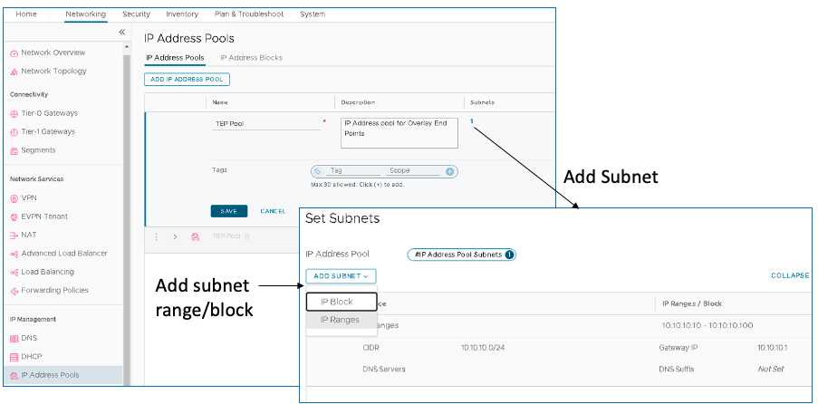
VMware NSX-T Manager: Create Tunnel Endpoint Pools
Tunnel Endpoints (TEPs) are used in the header of the outer (external) IP encapsulation to uniquely identify the hypervisor hosts originating and terminating the NSX-T encapsulation of overlay frames.
To create a TEP pool, log into VMware NSX-T Manager and navigate to Networking > IP Management > IP Address Pools > IP Address Pools.
VMware NSX-T Manager: Add vSphere to NSX-T Manager
Next, add the vSphere server as a Compute manager to the NSX-T manager. The NSX-T manager gets the inventory of ESXi hosts that will be used for Compute and Edge transport nodes.
To add the vSphere Server, log into NSX-T Manager and navigate to System > Fabric > Compute Managers.
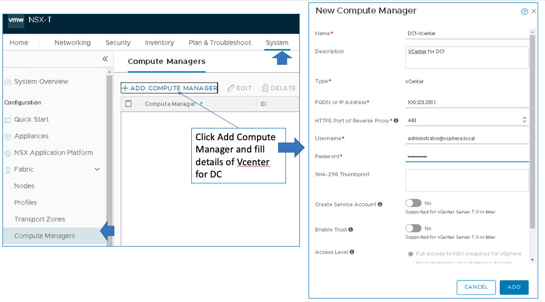
If adding the vSphere in the NSX-T Manager fails because of the Certificate of Compute Manager not valid error, then follow the VMware KB article to validate the vSphere certificate.
VMware vSphere: Configure VDS On ESXi Host
A vSphere Distributed Switch (VDS) provides centralized management and monitoring of the networking configuration of all hosts associated with the switch. For more information, please refer to the VMware documentation.
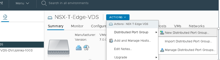
In VMware vSphere, under Networking, right-click the data center and select Distributed Switch > New Distributed Switch.
For this virtual distributed switch (VDS), create three Distributed Port Groups (DPGs) on the VDS. Enable VLAN Trunking on all the nodes. The configuration should be as follows:
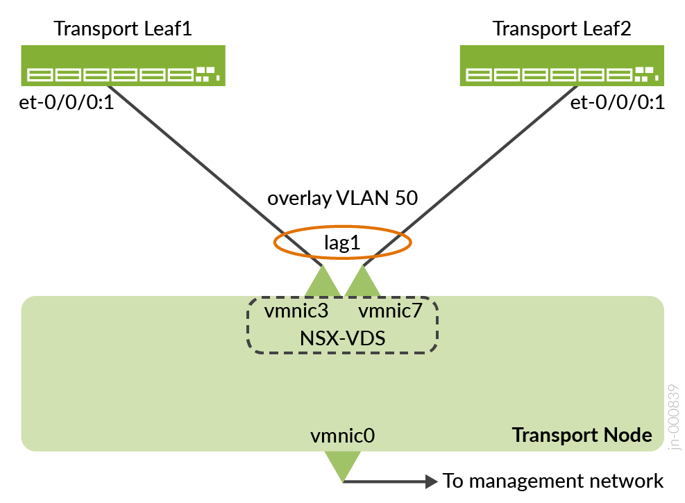
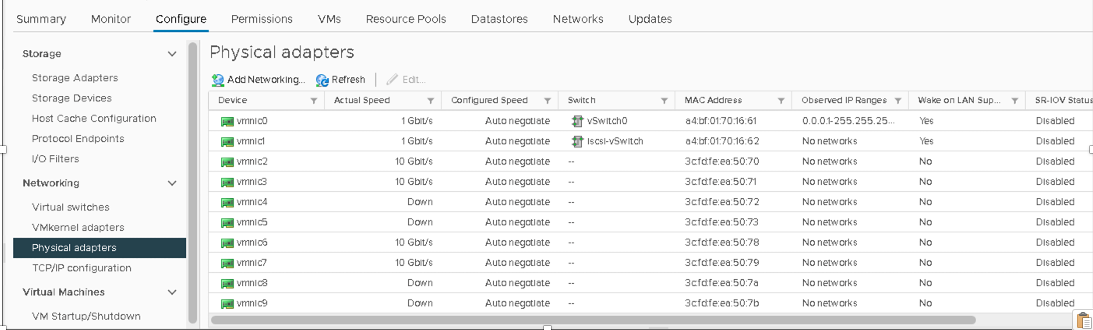
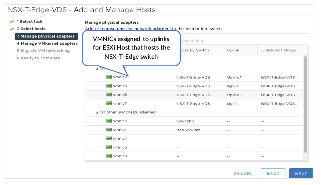
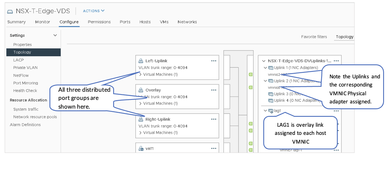
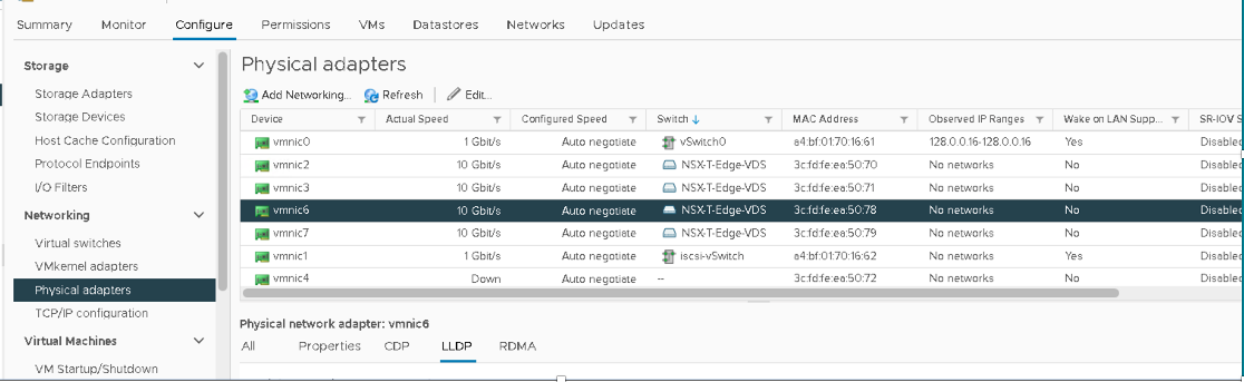
On the ESXi1_4 device (that hosts the NSX-T-Edge Node) that is connected to the border leaf switches, the following VMNICs are configured in the lab:
- Overlay VLAN: LAG1 (vmnic3+vmnic7). This is the aggregate Ethernet interface to border leaf switches.
- Left-uplink: vmnic2. This is the routed interface to border leaf1 et-0/0/0:0.
- Right-uplink: vmnic6. This is the routed interface to border leaf2 et-0/0/0:0.
The above VMNICs can be different depending on the setup. Ensure to select the appropriate switch interface to VMNIC mapping.
1. Create a VDS
In VMware vSphere, navigate to Networking and perform the following: Create a VDS (named NSX-T-Edge-VDS in this case) on the Edge Node Host and assign default uplinks. There are four default uplinks.
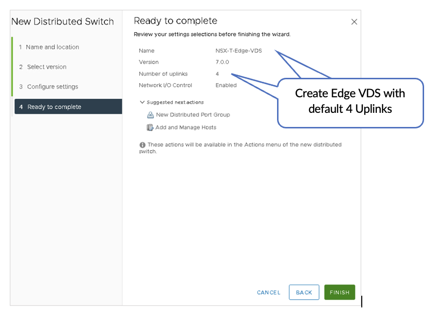
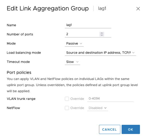
2. Configure LACP lag1
In VMware vSphere, navigate to Networking and perform the following:
Navigate to Networks > NSX-T-Edge-VDS > Configure > LACP to configure LACP lag1.
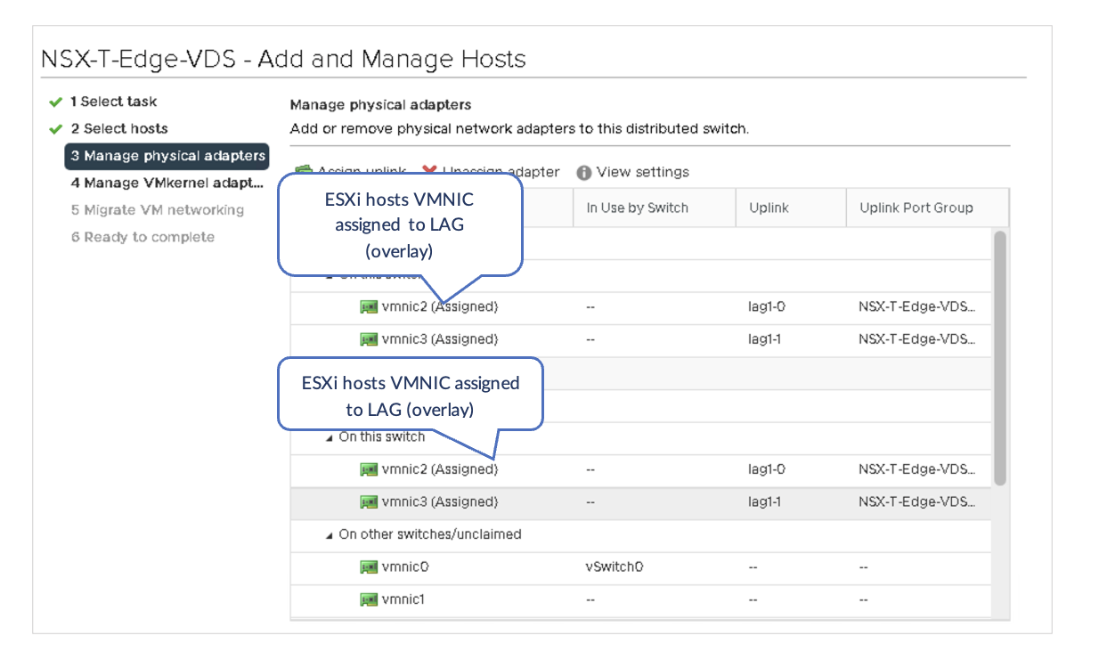
3. Assign VMNICs to Uplinks and LAG Ports
In VMware vSphere, perform the following:
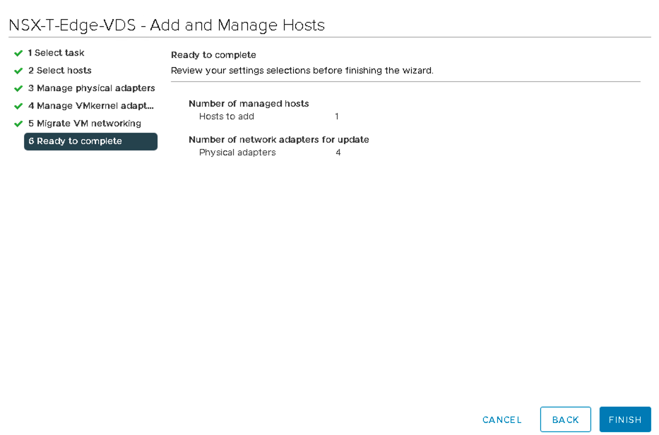
On NSX-T-Edge-VDS actions, use Add and Manage Hosts to assign the VMNICs to the uplinks and LAG ports.
Each host must be connected to the fabric as described in the Solution Architecture section.
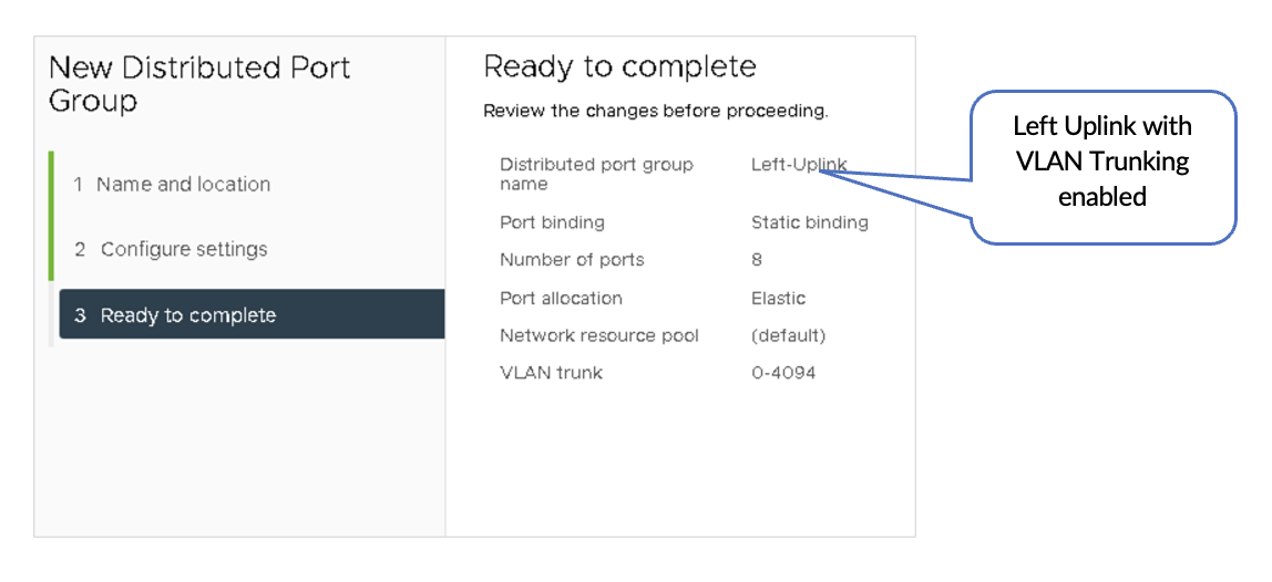
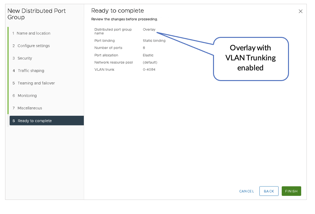
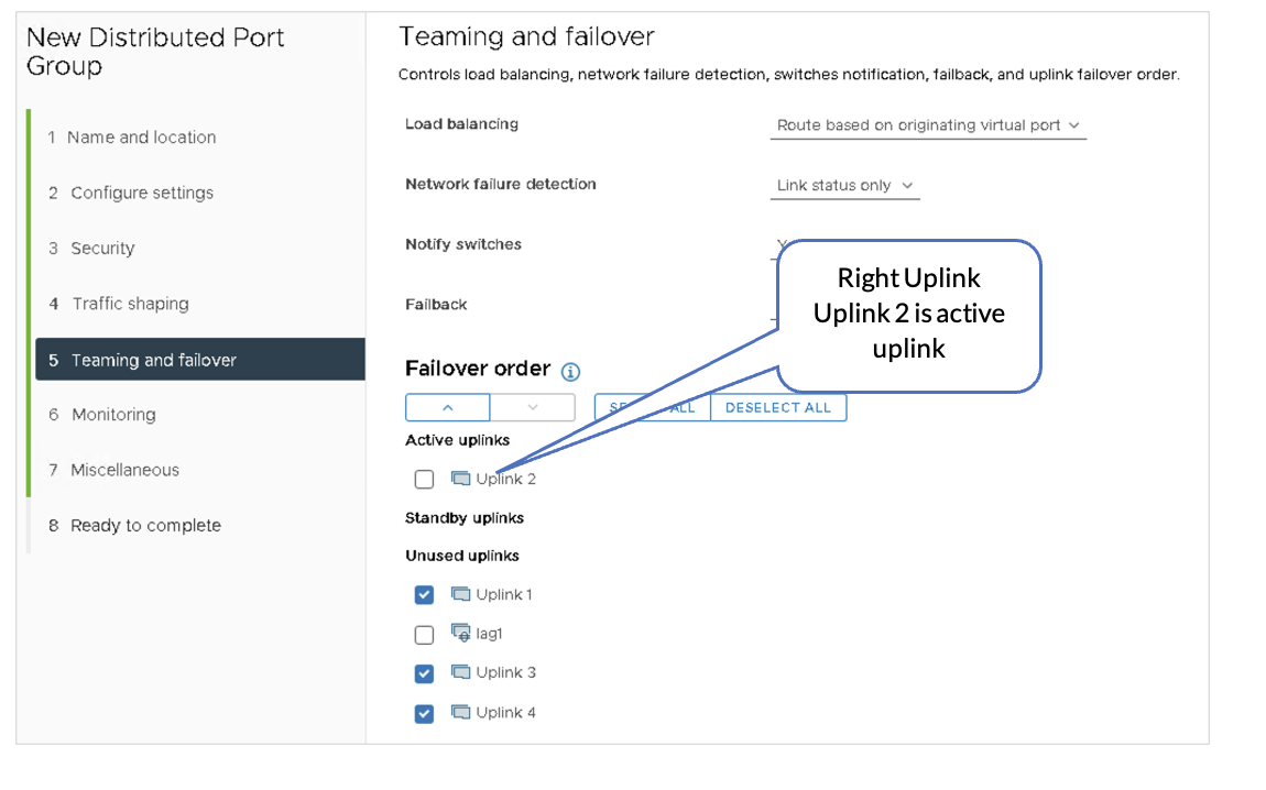
4. Create Three Distributed Port Groups
In VMware vSphere, perform the following:
- On the VDS, create the following:
- Port
- Distributed Port Group:
- Left-Uplink
- Overlay
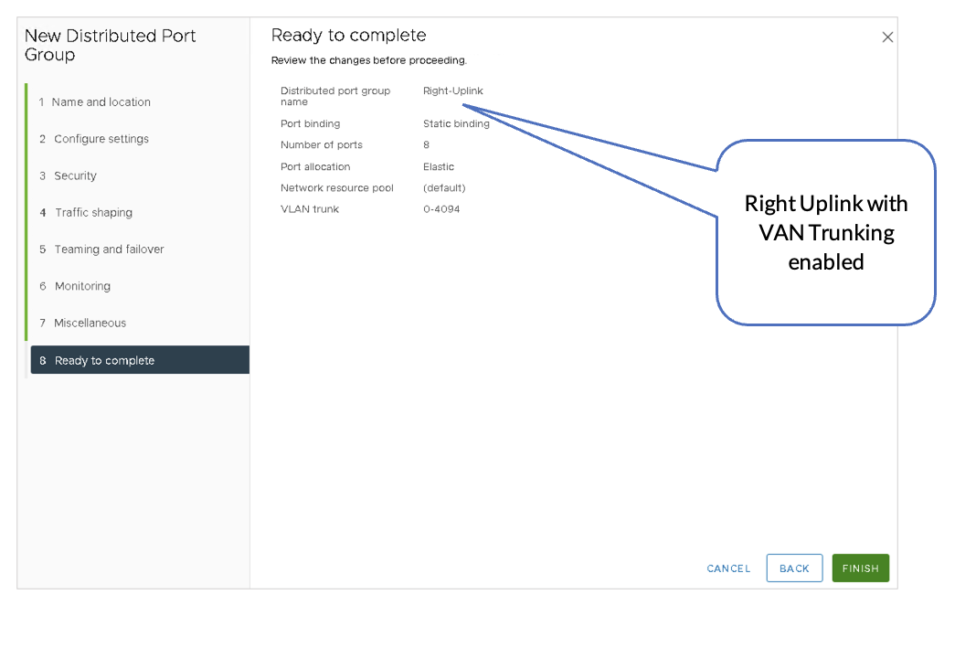
- Right-Uplink
- Enable VLAN Trunking on all the port groups.
Below are the three Distributed Port Groups added to the NSX-T-Edge-VDS switch.
- Left-Uplink Connects to the Border Leaf1
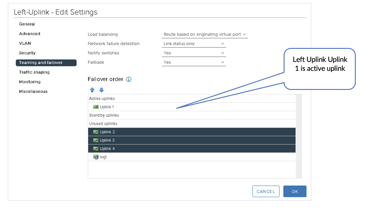
- Right-Uplink Connects to the Border Leaf2
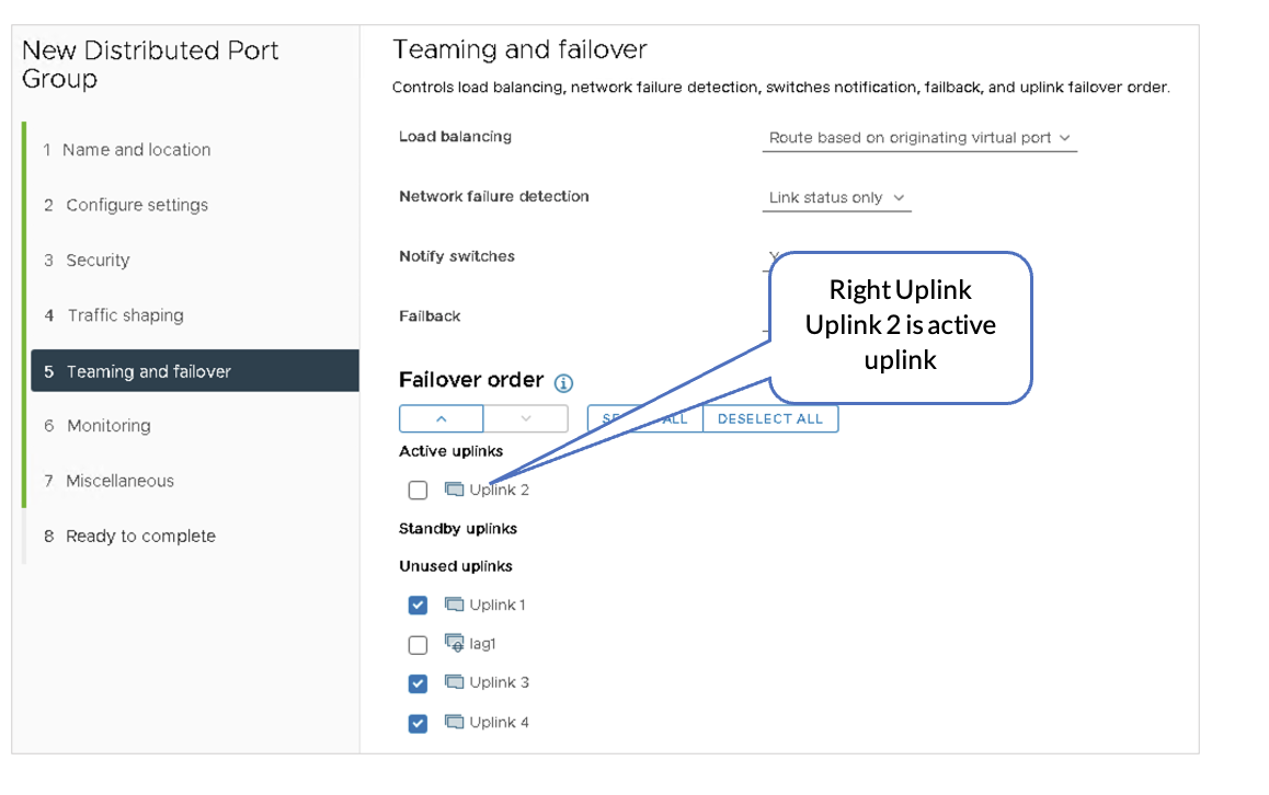
- Overlay Link is Used for VLAN Transport Traffic.
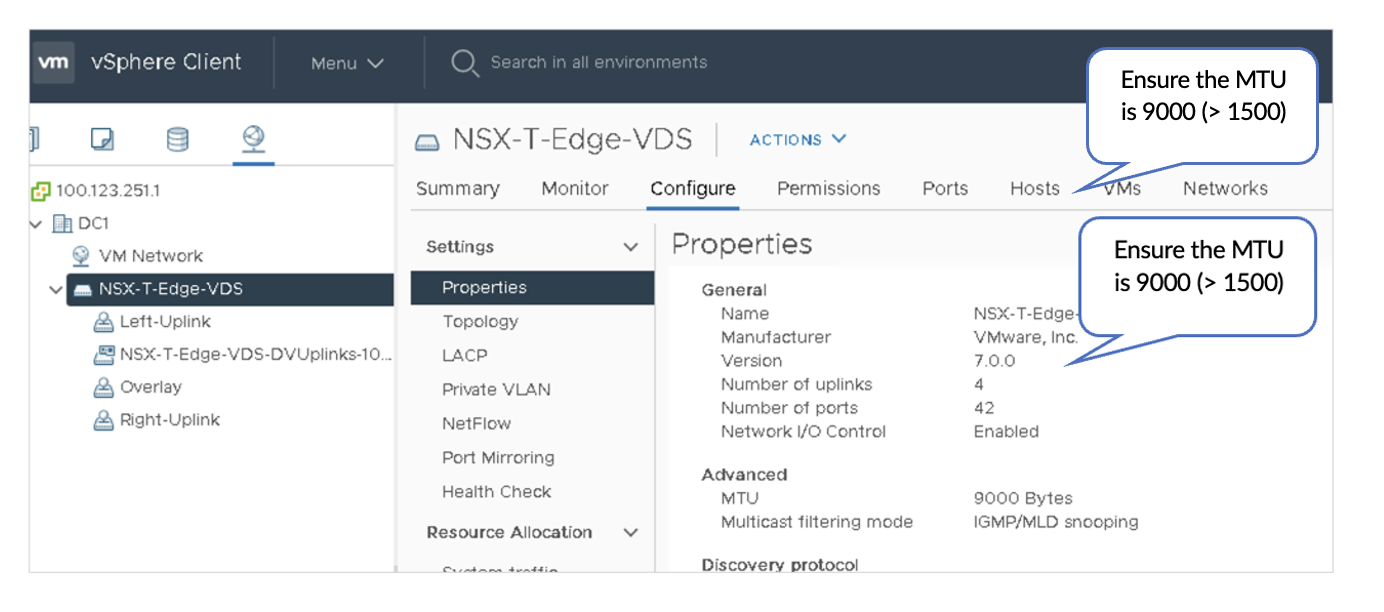
5. Review VDS
After configuring the NSXT-Edge-VDS switch, the switch should show the following port groups as configured. The Edge switch VM is assigned to the relevant port groups. Also, the physical adapters on the ESXi host are now allocated to the NSX-T-Edge-VDS.
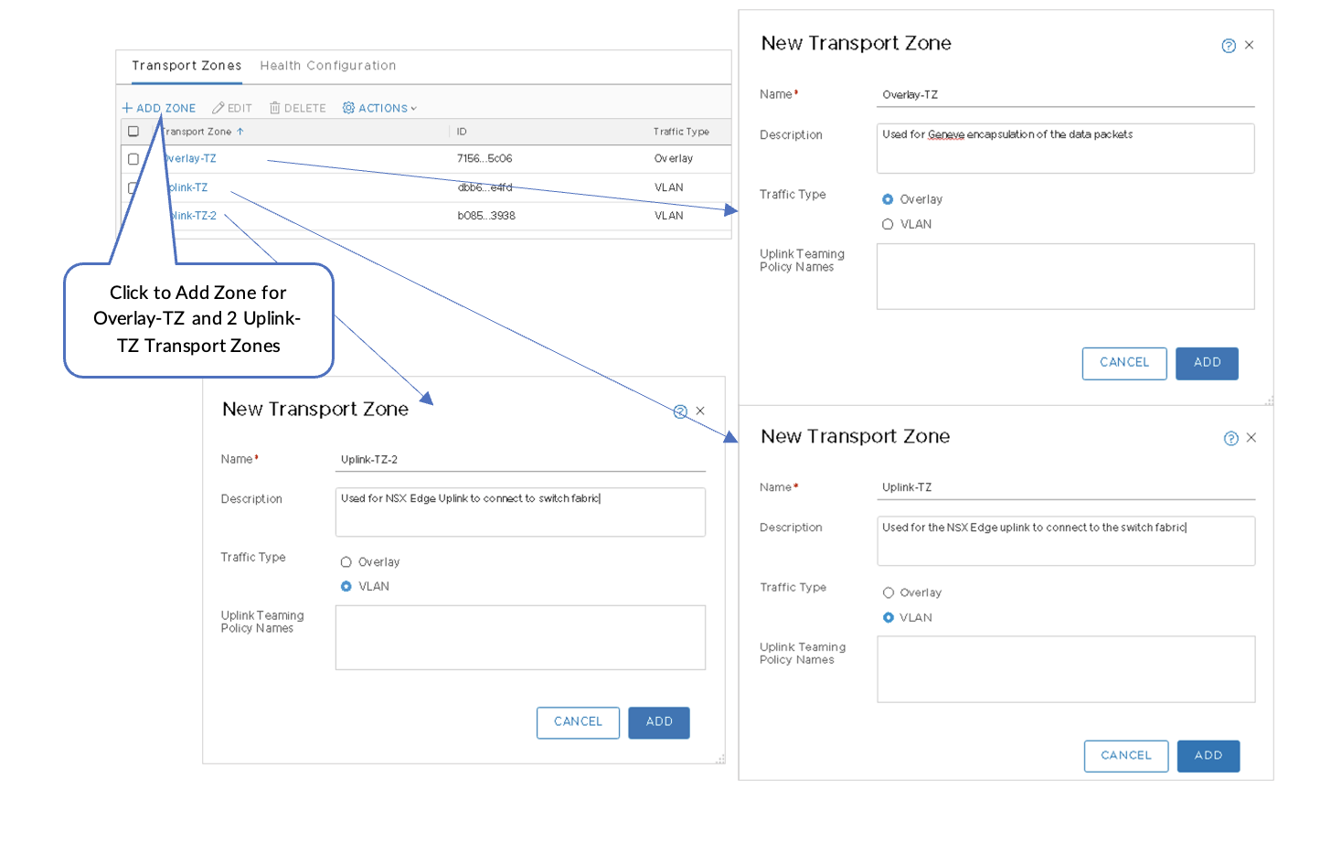
VMware NSX-T: Create Overlay and VLAN Uplink Transport Zones
Three Transport Zones need to be created:
- Overlay-TZ—Used for GENEVE encapsulation of data packets.
- Uplink-TZ—Used for the NSX Edge uplink to connect to the switch fabric.
- Uplink-TZ-2.
Create Three Transport Zones
To create three Transport Zones:
- In NSX-T Manager, navigate to System > Fabric > Transport Zones and then click +ADD ZONE .
- Select Overlay traffic type for Overlay-TZ.
- Select VLAN traffic type for Uplink-TZ.
- Select VLAN traffic type for Uplink-TZ-2.
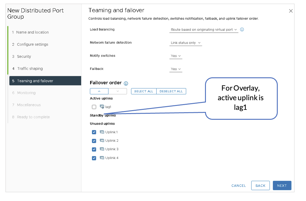
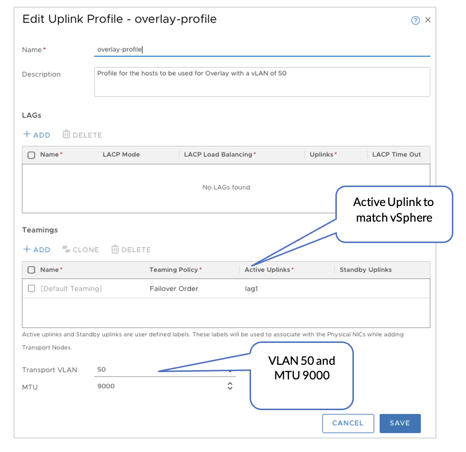
VMware NSX-T: Configure the Uplink Profiles for the Host and Edge Nodes
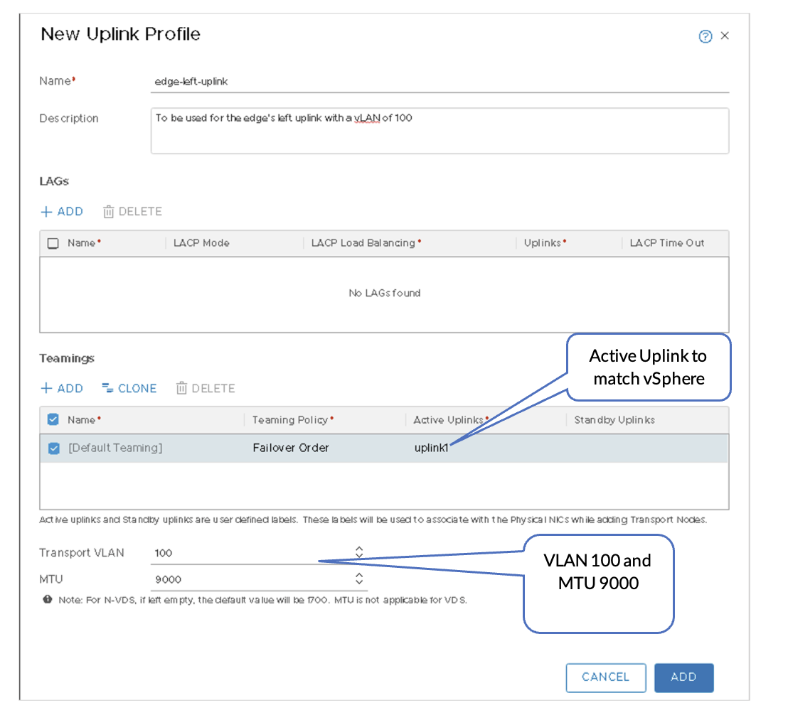
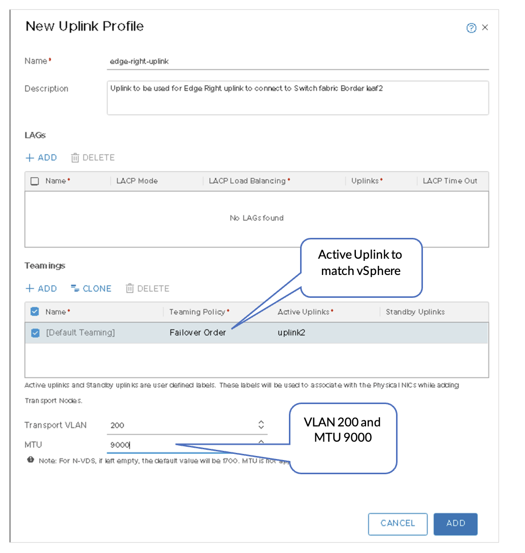
Now that the VDS is configured within vSphere, the uplink profiles must be created within NSX-T. The profiles created correspond to the uplinks Overlay, Edge-Right, and Edge-Left.
NSX-T Edge-left connects to Border Leaf-1 and NSX-T Edge-right connects to Border Leaf-2 for uplink/BGP redundancy.
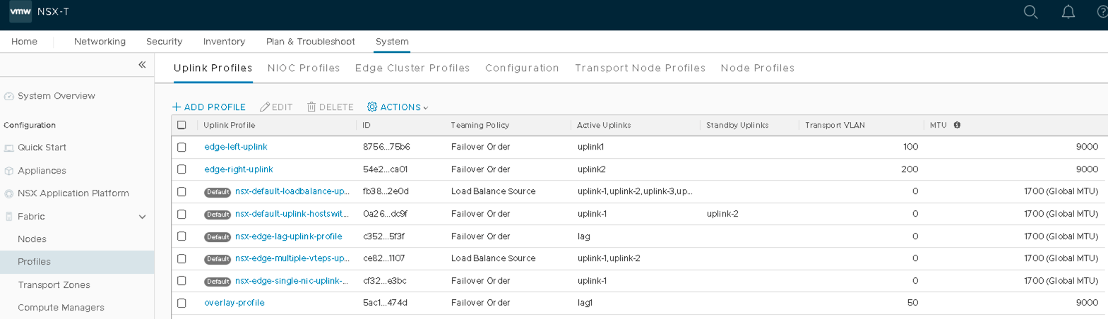
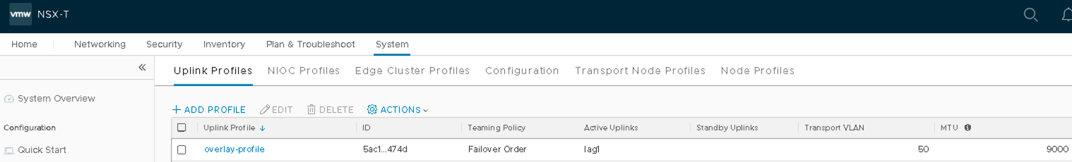
- Create Three Uplink Profiles
- In NSX-T Manager, navigate to System > Fabric > Profiles > Uplink Profiles, and then click ADD.
- Overlay-profile: VLAN 50 maps to lag1.
Figure 19: Overlay Profile with VLAN 50
- Edge-left-uplink profile: VLAN 100 maps to uplink1.
Figure 20: Edge-Left-uplink Profile with VLAN 100
- Edge-right-uplink profile: VLAN 200 maps to uplink2.
VMware vSphere: Add Transport Node Hosts to VDS
For transport node hosts, VDS should be configured so that the hosts can connect to the overlay transport network.
In VMware vSphere, under Networking, right-click the VDS created in the Juniper Apstra: Add the NSX-Manager section and add all the hosts that form part of the transport node to the VDS. Assign the respective VMNICs that will be used for overlay uplink (LAG link).
VMware NSX-T: Prepare the Compute Cluster
For an ESXi host to be part of the NSX-T overlay, it must first be added to the NSX-T fabric.
A fabric node is a node that is registered with the NSX-T management plane and has NSX-T modules installed.
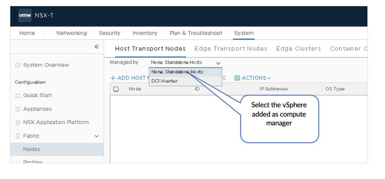
- In NSX-T Manager, navigate to System >
Fabric > Nodes >
Host Transport Nodes. Select the appropriate
vSphere instance from the Managed by list under Host Transport
Nodes.
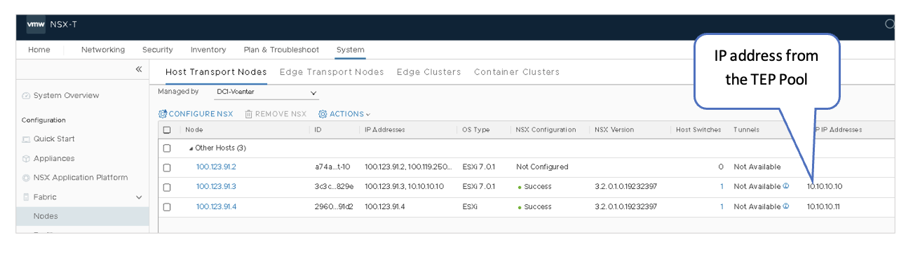
Figure 25: NSX-Manager Transport Nodes
- Select the ESXi host and then click Configure
NSX.
Figure 26: Configure NSX VDS on Transport Nodes
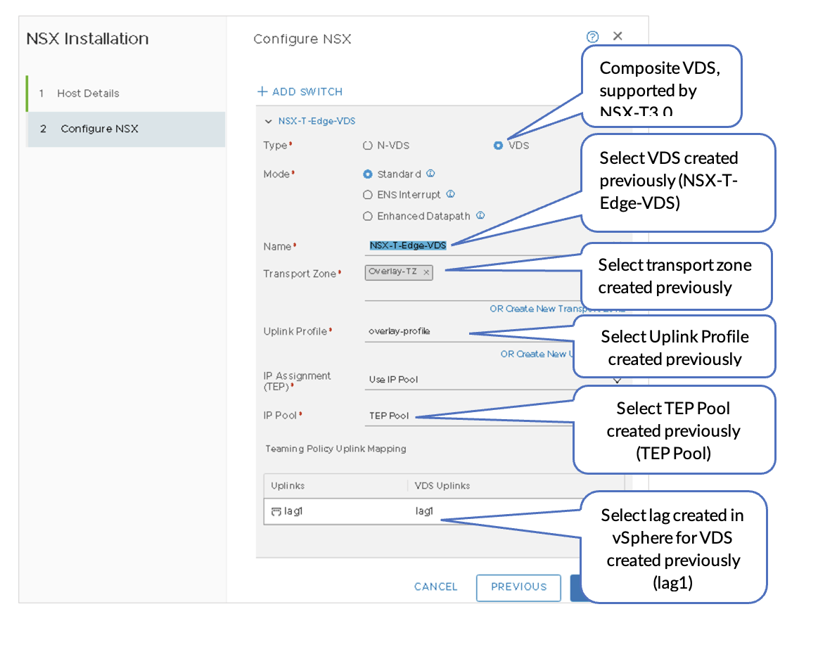 Figure 27: ESXi Configure NSX
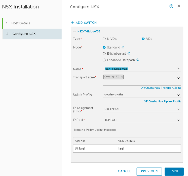
- Click Finish.
- Repeat steps 1 through 3 for all the ESXi hosts that need to be configured as Transport Nodes of the NSX-T cluster.
VMware NSX-T: Transport Nodes-Tunnel IPs
After NSX-T is configured on the nodes, the hosts should report the NSX configuration as “Success” and the node status as “Up.” The NSX version will also be displayed.
Remember the TEP IP addresses as they will be required in the later steps. These are the IP addresses assigned to each node. These IP addresses should be set from the TEP Address Pool that was configured earlier.
VMware NSX-T: Deploy NSX Edge Node and Create Edge Cluster
Next, the NSX Edge VM must be created. This will be used for north-south communication and BGP peering with the fabric.
- Create the Edge VM
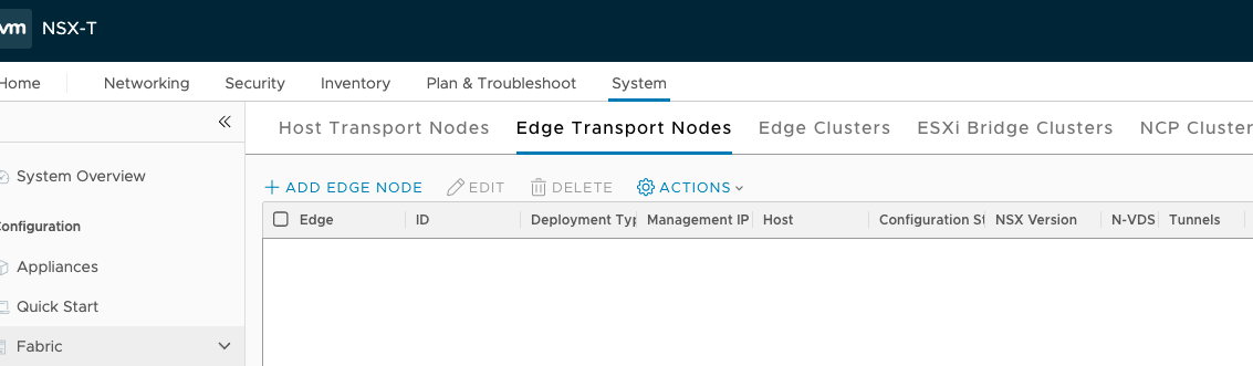
- Log on to NSX-T and navigate to System > Fabric > Edge transport Nodes.
- Click +ADD EDGE NODE.
Figure 29: NSX-T Edge Transport Node
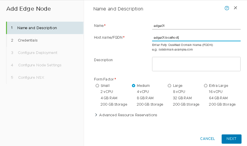
- Name the Edge VM edge01.
Figure 30: Adding Edge Node
- Enter the Credentials for the NSX Edge VM.
Note down the credentials to use them in the later steps.
Figure 31: Adding Credentials for NSX Edge VM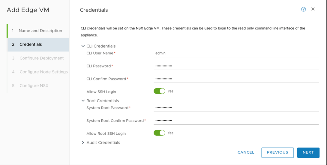
- In the next step, Select the Compute Manager, Cluster, and Datastore to deploy the Edge VM.
- Next, configure the Edge VM Network Settings, such as the management IP, default
gateway IP, DNS, and NTP server for the edge node.
- Within vSphere, a VDS was created With three Uplinks. Create one NSX-T VDS for each
of the uplinks in the vSphere VDS in NSX-T, Overlay, Edge-Right, and Edge-Left VDS.
Name the first NSX-T VDS:
- Name the first NSX-T VDS as nvds-overlay.
- Set transport zone to Overlay-TZ.
- Set the Uplink Profile to overlay-profile.
- Select TEP-Pool for the IP Pool.
Figure 32: NVDS Overlay for Edge Node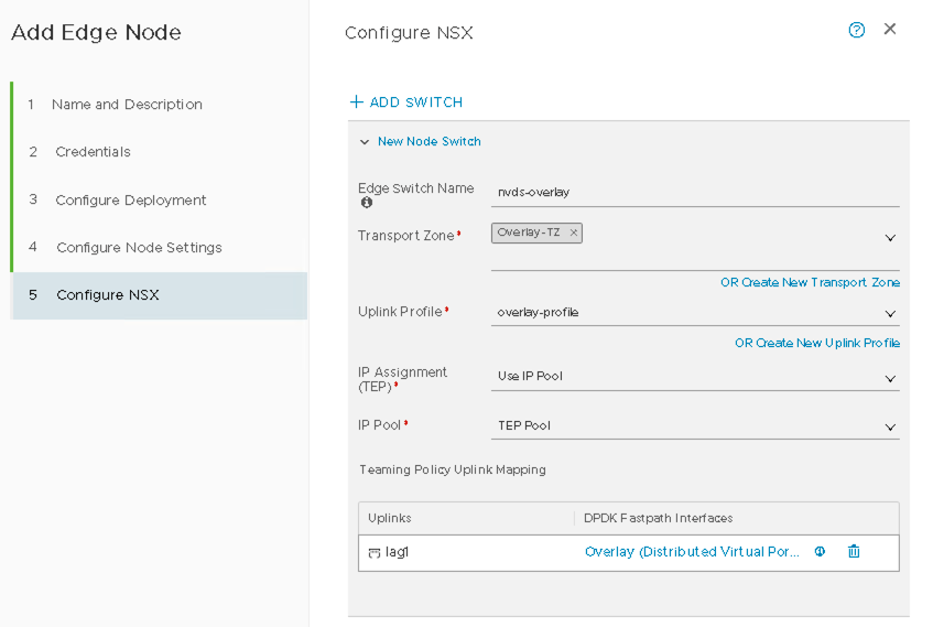
- Name the Second NSX-T VDS:
- Name the second NSX-T VDS as nvds-left.
- Set the Transport Zone to Uplink-TZ.
- Set the Uplink Profile to edge-left-uplink.
Figure 33: NVDS Left for Edge Node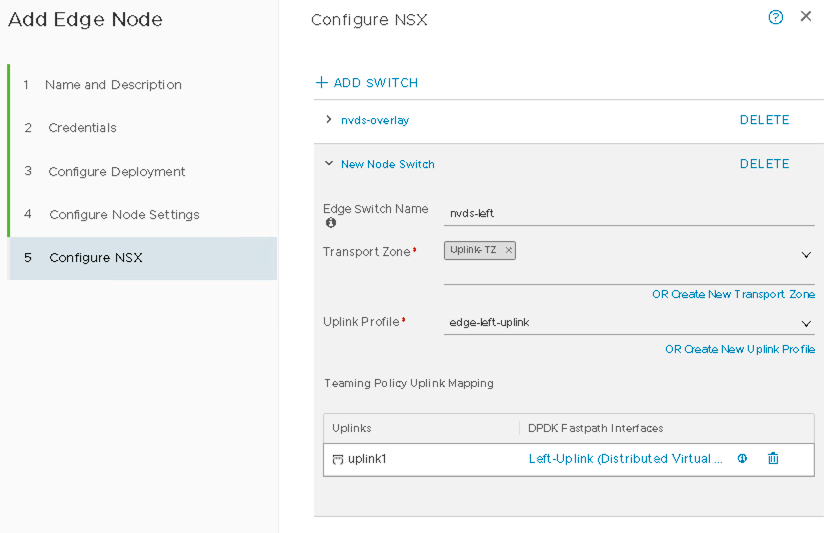
- Name the Third NSX-T VDS:
- Name the third NSX-T VDS as nvds-right.
- Set the Transport Zone to Uplink-TZ.
- Set the Uplink Profile to edge-right-uplink.
Figure 34: NVDS Right for Edge Node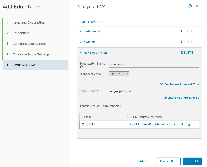
- Within vSphere, a VDS was created With three Uplinks. Create one NSX-T VDS for each
of the uplinks in the vSphere VDS in NSX-T, Overlay, Edge-Right, and Edge-Left VDS.
- Verify NSX-T Edge Creation
A successful message is displayed once the NSX-T Edge is created. The TEP IP address must be assigned from the previously configured TEP pool.
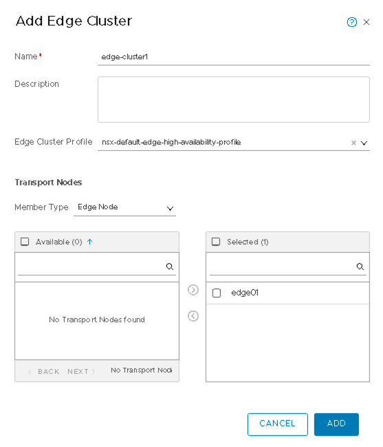
- Add Edge Cluster
- In NSX-T Manager, navigate to System > Fabric > Nodes > Edge Clusters > ADD.
- Name the cluster as edge-cluster1.
- Select nsx-default-edge-high-availability-profile for the Edge Cluster Profile.
- Select Edge Node for the Member Type edge01 in edge-cluster1.
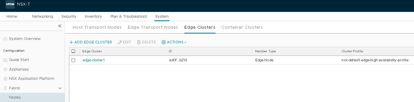
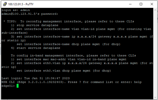
- Verify Edge Cluster
To verify that SSH connectivity exists, and the credentials are set up correctly, SSH to the edge node and login.
VMware NSX-T: Create a T-1 Gateway
A Tier-1 Gateway is a logical router that provides East-West communication between VMs in the NSX-T domain.
Create a Tier-1 Gateway
In NSX-T Manager, navigate to Networking > Connectivity > Tier-1 Gateways > ADD TIER-1 GATEWAY and then enter the gateway name as T1-1.
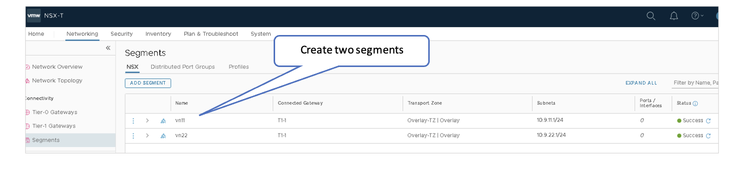
VMware NSX-T: Create Logical Segments
Segments are virtual L2 networks, and VMs are launched in segments. Segments are connected to the T1 Gateway to enable connectivity between the VMs.
- In NSX-T Manager, navigate to Networking > Connectivity > Segments > Segments > ADD SEGMENT.
- Name the first segment as vn11.
- Select T1-1 | Tier1 under Connected Gateway list to designate Tier 1 Gateway.
- Select Overlay-TZ under Transport Zone to specify the transport zone for the overlay.
- Enter the subnet to be used: 10.9.11.1/24.
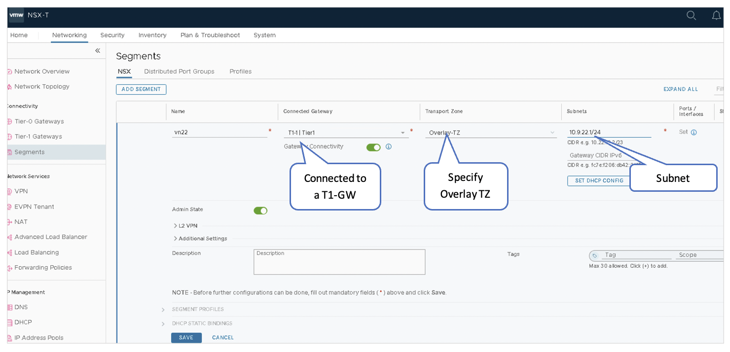
Add Another Segment
- Name the second segment as vn22.
- Select T1-1 | Tier1 under Connected Gateway to designate Tier 1 Gateway.
- Select Overlay-TZ under Transport Zone to specify the transport zone for the overlay.
- Enter the subnet to be used: 10.9.22.1/24.
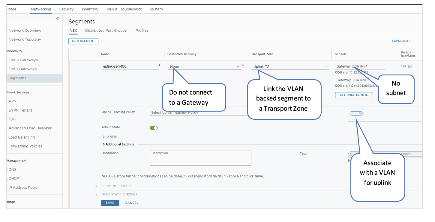
VMware NSX-T: Create VLAN Backed Logical Segments
A VLAN-backed segment enables the Tier-0 gateway to establish BGP sessions with the fabric. The VLAN-backed segment serves as the North-South data path of the VMs in NSX to/from the rest of the Data Center Fabrics.
- Create One VLAN-Backed Segment for Each Uplink:
- In NSX-T Manager, navigate to Networking > Connectivity > Segments > Segments > ADD SEGMENT.
- Name the first segment as uplink-seg-100.
- Do not select a gateway under Connected Gateway.
- Select Uplink-TZ under Transport Zone to specify the transport zone for the overlay.
- Do not enter a subnet to be used.
-
Under VLAN, associate VLAN 100.
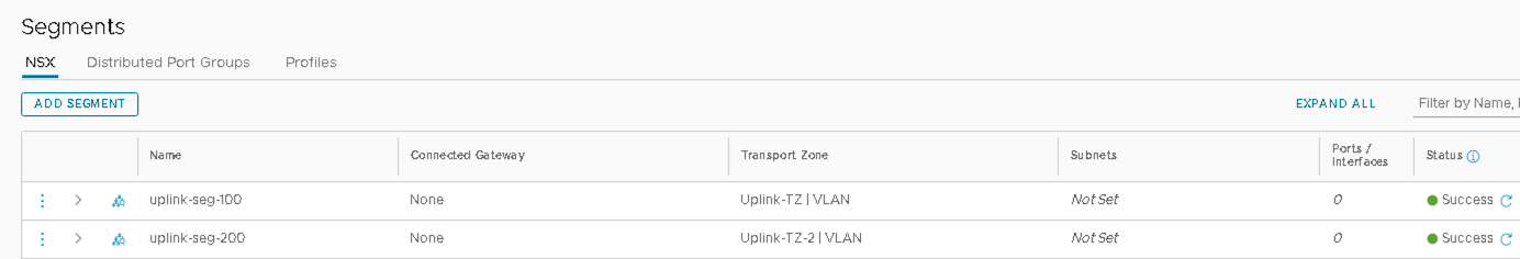
- Add Another VLAN Segment
- Name the second segment as uplink-seg-200.
- Do not select a gateway under Connected Gateway.
- Select Uplink-TZ under Transport Zone to specify the transport zone for the overlay.
- Do not enter a subnet to be used.
- Under VLAN, associate VLAN 200.
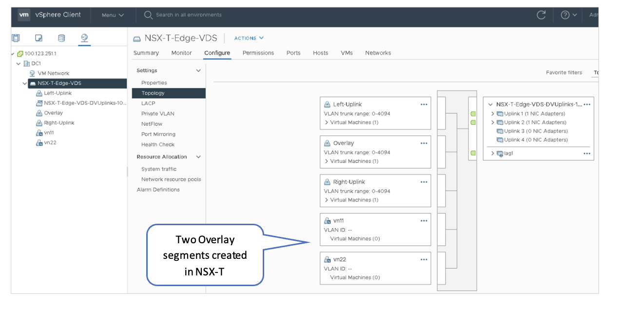
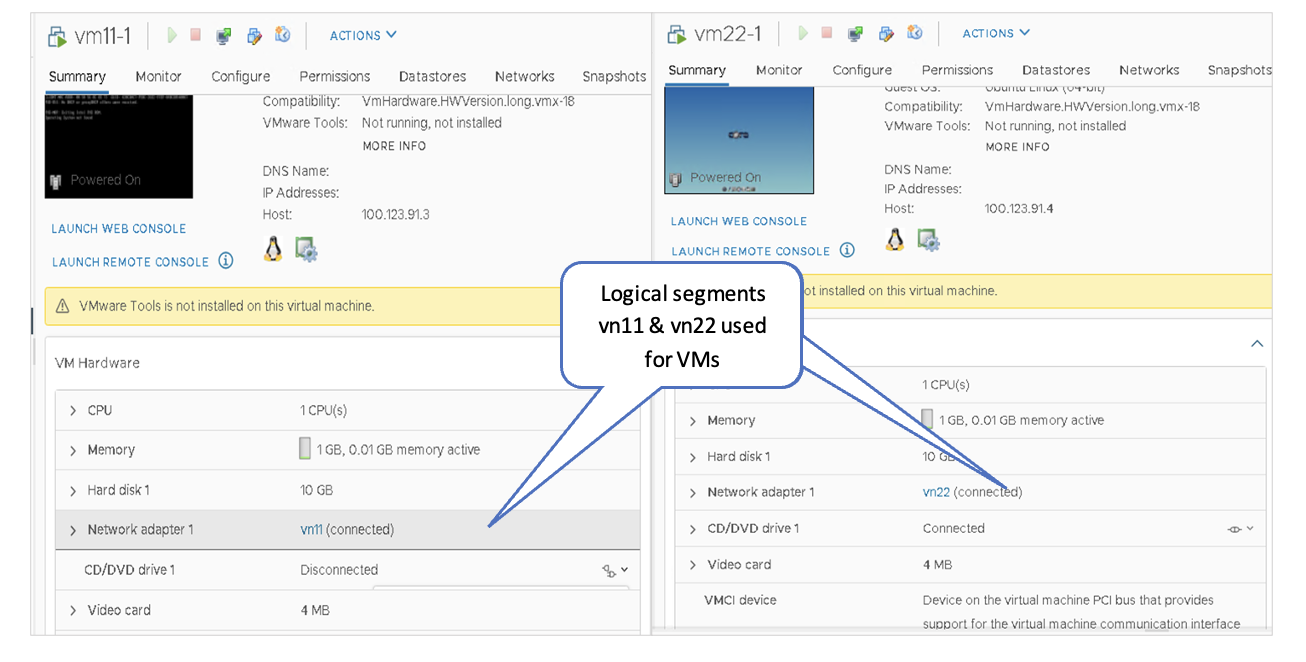
VMware vSphere: Confirm the Creation of the Logical Segments
The Logical Segments created in the previous steps should be reflected in the vSphere client. Verify that logical segments created in NSX-T are present in the vSphere client. In the vSphere Client, navigate to Distributed vSwitch > Configure > Topology.
VMware vSphere: Create VMs in the Segments
Create two test VMs on each of the Transport Nodes in the cluster:
- Connect the first VM on each Transport Node to the vn11 logical segment on NSX-T-Edge-VDS, which will allow testing of the vn11 overlay segment for that Transport Node.
- Connect the second VM on each Transport Node to the vn22 logical segment on NSX-T-Edge-VDS, which will allow testing of the vn22 overlay segment for that Transport Node.
For more information, refer to the VMware vSphere guide for creating a VM and setting up a network adapter.
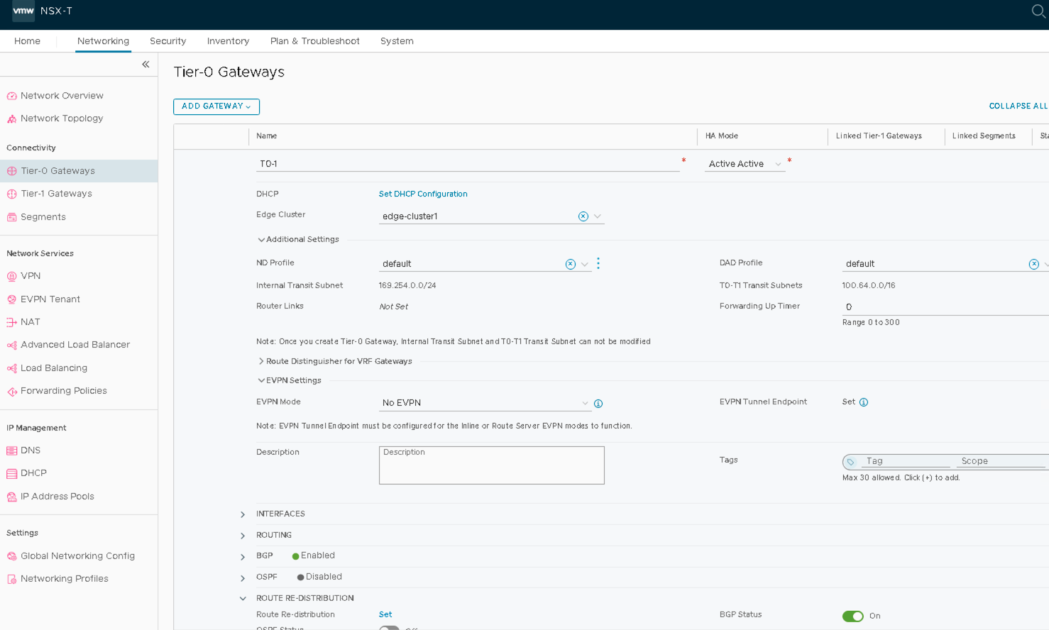
VMware NSX-T: Create Tier0 Gateways T0-1
A Tier-0 Gateway connects the NSX-T virtual fabric with the physical switch fabric. This is accomplished by using BGP to communicate with the Top of Rack (ToR) switches. In this document, each Transport Node is connected to a pair of QFX-5120 leaf switches, while the Edge VM host (Edge01) is connected to a pair of QFX5130 border leaf switches.
To add a Tier-0 Gateway:
- In NSX-T Manager, navigate to Networking > Connectivity > Tier-0 Gateways > ADD GATEWAY.
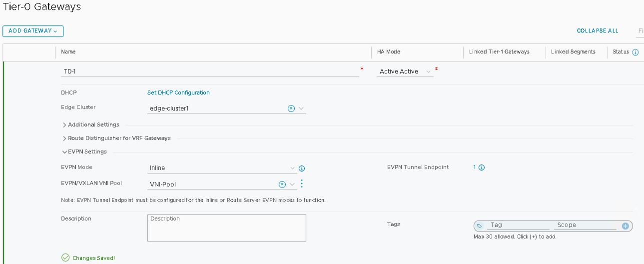
- Name the Tier-0 Gateway as T0-1.
- Set HA-Mode to Active-Active.
- Set the Edge-cluster on T0-1 to edge-cluster1.
- Save and proceed through the next steps to add interfaces, BGP, and route-redistribution.
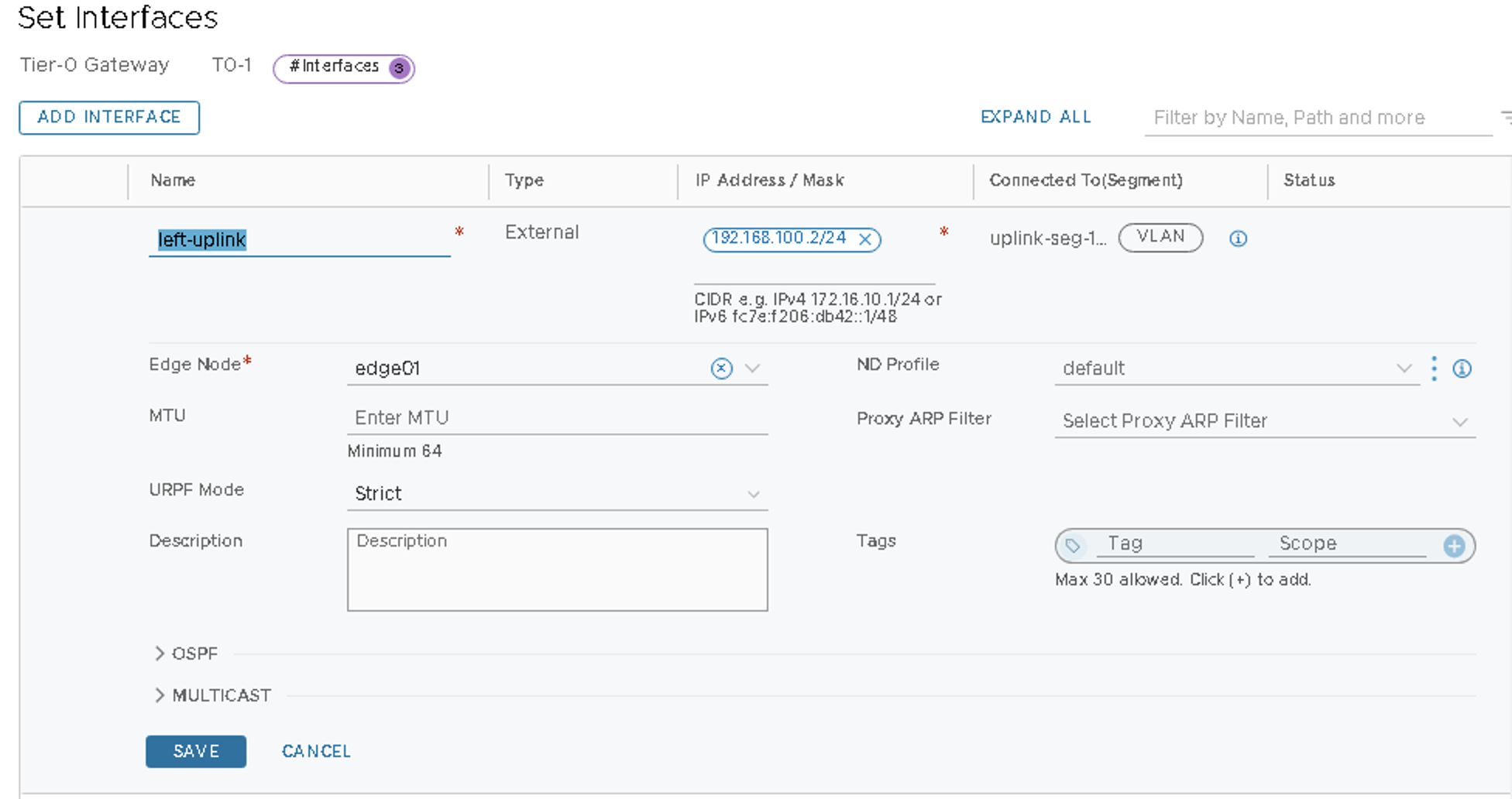
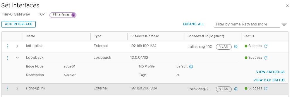
VMware NSX-T: Configure the Interfaces on the T0 Gateway
Tier-0 Gateway (T0-1 gateway) requires one interface for each uplink segment.
- In NSX-T Manager, navigate to Networking > Connectivity > Tier-0 Gateways > Edit T0-1.
- To add two external tnterfaces for the fabric within the Tier-0 Gateway screen for the
T0-1 Tier-0 Gateway created above:
- Click Set.
- Click ADD INTERFACE to add the first interface and configure the
following:
- Name the interface as left-uplink.
- Set type External.
- Set the IP Address/Mask as 192.168.100.2/24.
- Connect to segment as uplink-seg-100.
- Set the Edge Node as edge01.
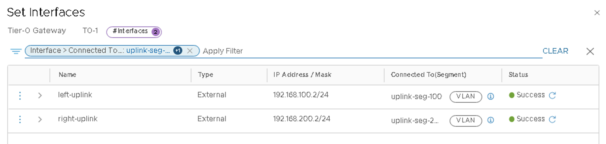
- Click ADD INTERFACE to add the second interface and configure the
following:
- Name the interface as right-uplink.
- Set type External.
- Set the IP Address/Mask as 192.168.200.2/24.
- Connect to segment as uplink-seg-200.
- Set the Edge Node as edge01.
VMware NSX-T: Configure Loopback Interface on T0 Gateway
The loopback interface is used to create a BGP session with switch Fabric border leaf switches.
- In NSX-T Manager, navigate to Networking > Connectivity > Tier-0 Gateways > Edit T0-1.
- To add loopback interface towards the Fabric within the Tier-0 Gateway page for the
T0-1 Tier-0 Gateway created above:
- Click Set.
- Click ADD INTERFACE to add loopback:
- Name the loopback interface as Loopback.
- Set type Loopback.
- Set the IP Address/Mask as 10.0.0.1/32.
Figure 47: Configure Loopback Interface to Connect to the Border leaf switches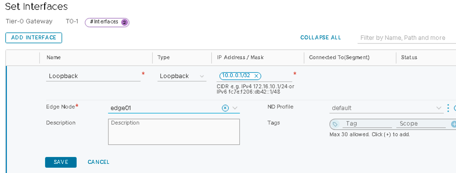
VMware NSX-T: Configure BGP on the T0 Gateway
In NSX-T Manager, navigate to Networking > Connectivity > Tier-0 Gateways > Edit T0-1
Configure BGP
- Within the Tier-0 Gateway page for the T0-1 Tier-0 Gateway created above:
- Click BGP.
- Set Local AS to 65000.
- Enable BGP.
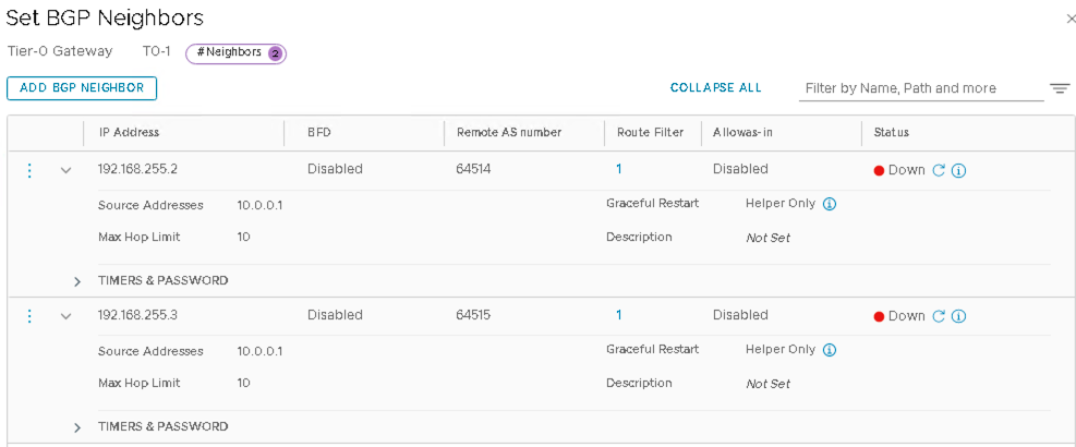
- Click Set next to BGP Neighbors.
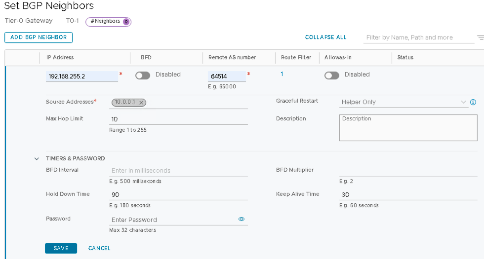
- Click ADD BGP NEIGHBOUR to add the first BGP neighbor.
Configure the Loopback IP Address of Border Leaf1
- In the Juniper Apstra UI navigate to Blueprints > <blueprint-name>
> Staged > Physical > Nodes.
- Refer to column name Loopback IPv4.
- In the following figures, the loopback IP Address from Juniper Apstra is 192.168.255.2, but this can vary.
- Set BFD to be Disabled.
Configure the Remote AS Number as Border Leaf1 ASN number
- In the Juniper Apstra UI navigate to Blueprints > <blueprint-name>
> Staged > Physical > Nodes.
- Refer to column name ASN.
- In the below figures the ASN from Juniper Apstra is 64514, but this can vary.
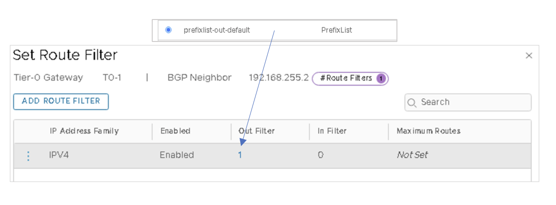
- Set Route Filter to be 1 with IPV4 Route Filter enabled and Out filter as
prefixlist-out-default.
Figure 55 Setting Route Prefix List
- Set Allowas-in as Disabled.
- Under Timers & Password, set Hold Down Time as 90 and Keep Alive Time as
30. Figure 48: Add Border Leaf1 Loopback as the Neighbor
- Click ADD BGP NEIGHBOUR to add the second BGP neighbor.
Configure the Loopback IP Address of Border Leaf2:
- In the Juniper Apstra UI navigate to Blueprints > <blueprint-name> > Staged > Physical > Nodes.
- In the following figures, the loopback IP Address from Juniper Apstra is 192.168.255.3, but this can vary.
- Set BFD to be Disabled.
Configure the Remote AS Number as Border Leaf2 ASN Number:
- In the Juniper Apstra UI navigate to Blueprints > <blueprint-name> > Staged > Physical > Nodes.
- Refer to column name ASN.
- In the following figures, the ASN from Juniper Apstra is 64554, but this can vary.
- Select 1 for Route Filter.
- Enable IPV4 Route Filter.
- Select prefixlist-out-default for Out Filter.
- Set Allowas-in as Disabled.
- Select Max Hop Limit as 10.
- Set Hold Down Time as 90 and Keep Alive Time as 30 under Timers & Password:
BGP status for the two neighbors will be down until Apstra is configured.
VMware NSX-T: Configure In-Line Mode and Route-Redistribution on the T0 Gateway
- In NSX-T Manager, navigate to Networking > Connectivity > Tier-0 Gateways > Edit T0-1.
- Within the Tier-0 Gateway, screen for the T0-1 Tier-0 Gateway created above:
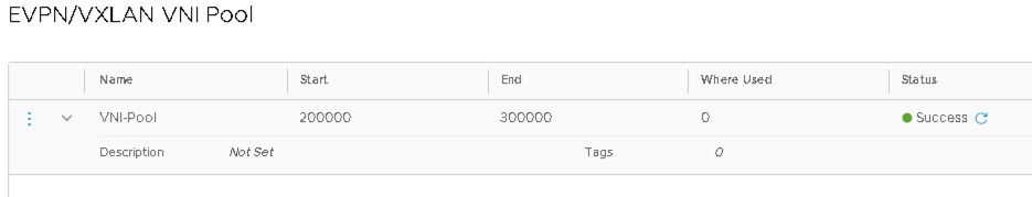
- Select EVPN Mode as inline.
- Click the three vertical dots and create a new VNI-Pool for the EVPN/VXLAN VNI-Pool.
Figure 50: T0 Gateway EVPN VXLAN VNI Pool
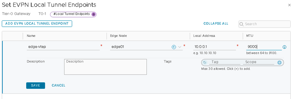
- Click Set near EVPN Tunnel Endpoint and configure the following:
- Name EVPN local tunnel endpoint as edge-vtep.
- Edge-Node name: edge01 (created as per VMware NSX-T: Deploy NSX Edge Node and Create an Edge Cluster).
- Local Address: 10.0.0.1 (this is the loopback address of T0 Gateway as configured in VMware NSX-T: Configure Loopback interface on T0 Gateway).
- MTU: 9000.
- Save changes to the Tier-0 Gateway.
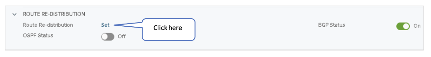
Within the Tier-0 Gateway screen for the T0-1 Tier-0 Gateway created above:
- Expand and click Route Re-Distribution. Figure 53: Configure Route Re-distribution
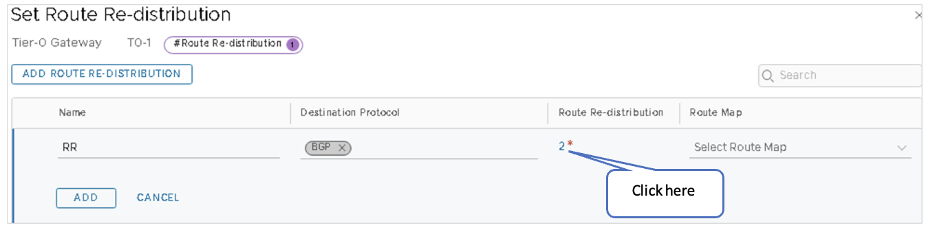
- Under Advertised Tier-1 Subnets, check only the following sources:
- Connected Interfaces & Segments
- Service Interface Subnet
- Static Routes
- Connected Segment
Ensure no other boxes are checked.
Figure 54: Set Route-Redistribution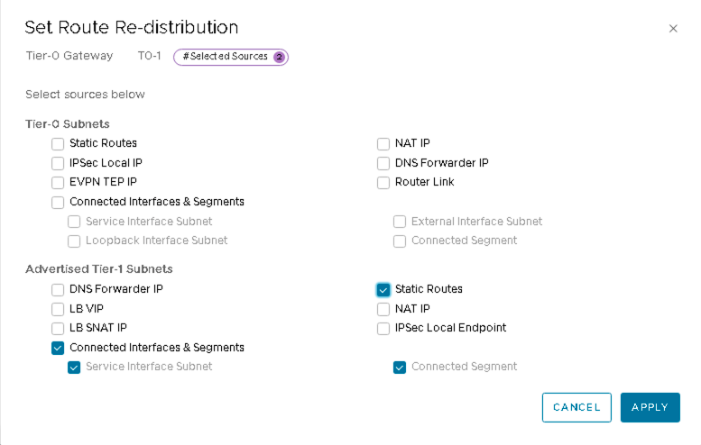
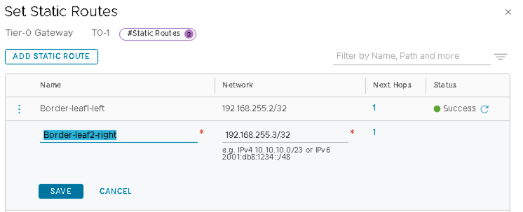
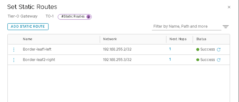
VMware NSX-T: Create a Static Route to Loopback on Border Leaf Switches
A static route needs to be created for the reachability of the loopbacks on the border leaf switches. These interfaces are used to establish BGP neighbors between NSX-T and the border leaf switches.
- In NSX-T Manager, navigate to Networking > Tier-0 Gateways.
- Select T0-1 Gateway and edit, then select Set.
- Add Loopback 192.168.255.2/32 of Border Leaf1 and 192.168.255.3/32 of Border Leaf2 as static routes.
Ensure to check Apstra for the correct loopbacks for the border leaf switches.
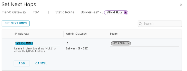
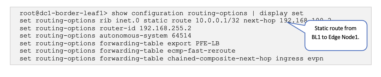
Static Route to Border Leaf1
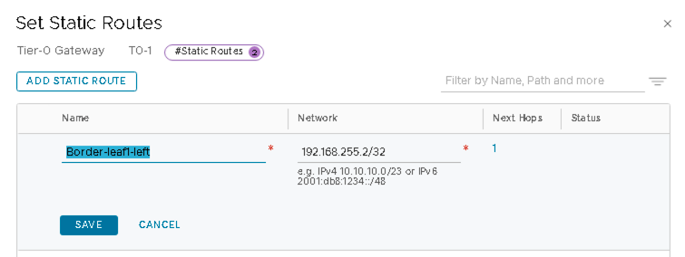
Click SET NEXT HOPS and add 192.168.100.1 (IP of the border leaf1 switch interface).
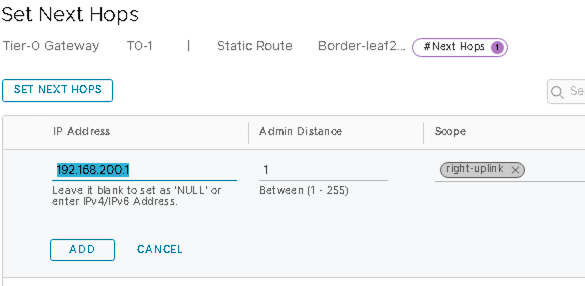
Static Route to Border Leaf2
For the static route to border leaf2, click SET NEXT HOPS and add 192.168.200.1 (IP of the border leaf2 switch interface).
VMware NSX-T: Create IP Prefix lists on T0 Gateway
The IP Prefix list must be set up not to allow advertising of the fabric IPs.
Add the IP Prefixes as below:
- In NSX-T Manager, navigate to Networking > Tier-0 Gateways.
- Select T0-1 Gateway, expand
Routing, and click on the number beside IP Prefix
Lists to add or edit the prefix list.
prefixlist-out-default is the prefix-list set on the T0 Gateway BGP, as mentioned in VMware NSX-T: Configure BGP on the T0 GW.
Figure 60: Adding Prefixes to prefixlist-out-default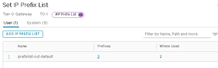
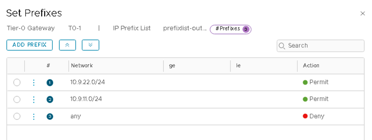
- Click on 1 (or any number) under Prefixes to add prefixes.
- Click Edit and add the following prefixes.
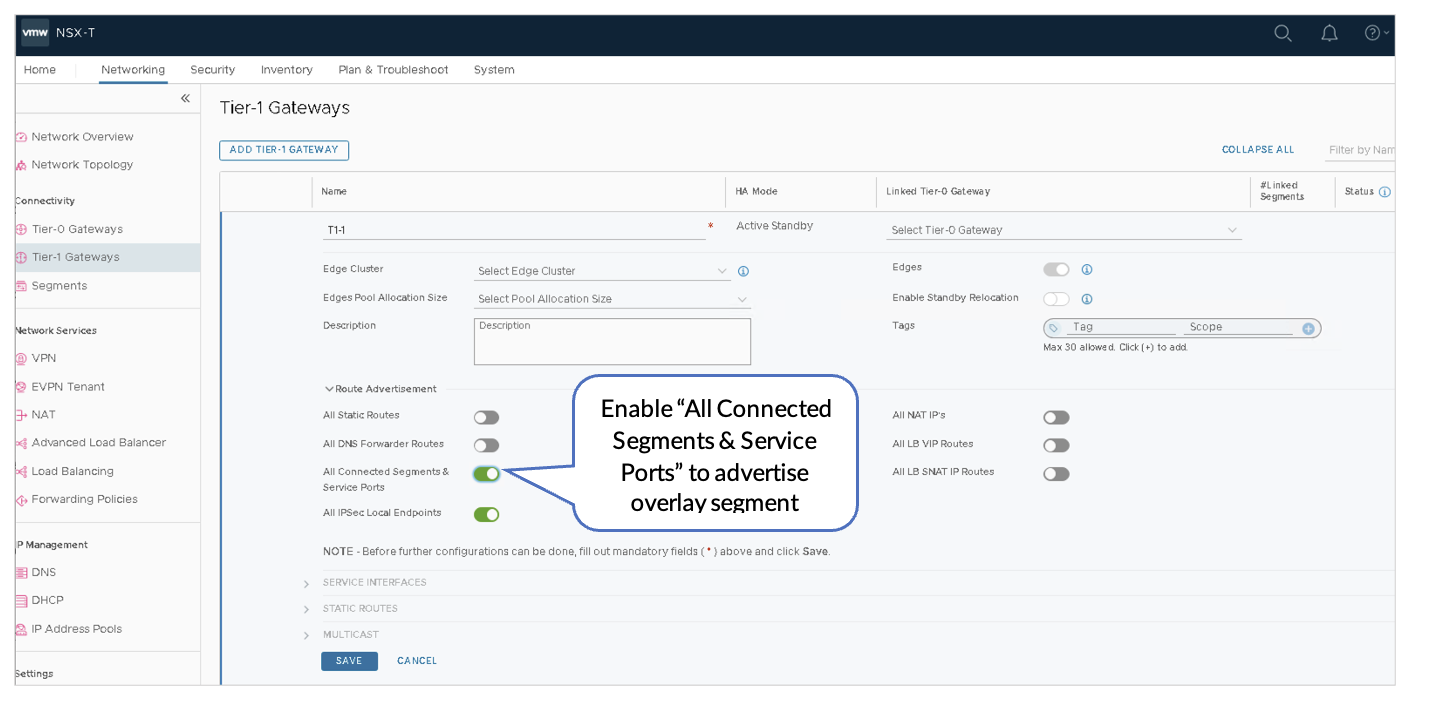
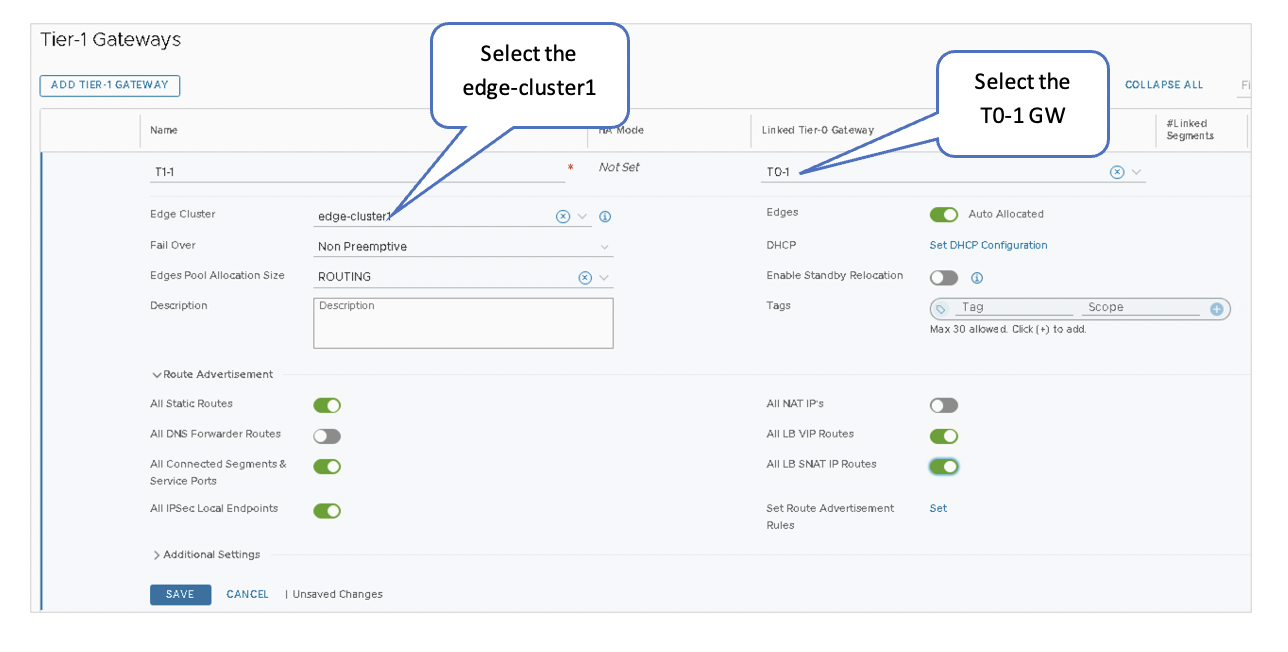
VMware NSX-T: Connect the T1 and T0 Gateways
Connecting the T1 and T0 Gateways enables east-west connectivity and north-south communication to the VMs in the NSX-T Domain.
Connect the Gateways
- In NSX-T Manager, navigate to Networking > Tier-1 Gateways.
- Select T1-1 Gateway.
- Under Linked Tier-0 Gateway, select T0-1.
- Add the edge-cluster1 setup in VMware NSX-T: Deploy NSX Edge Node and Create an Edge Cluster.
- Select the following under the Route Advertisement:
- All Static Routes
- All LB VIP Routes
- All LB SNAT IP Routes
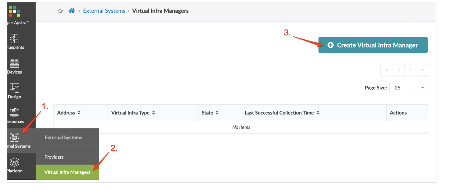
Juniper Apstra: Add the NSX-Manager
For Juniper Apstra to remediate inconsistencies between the virtual infrastructure and the physical IP fabric, the NSX-T manager should be added in Juniper Apstra.
In the Juniper Apstra UI, navigate to External Systems > Virtual Infra Managers > Create Virtual Infra Manager and add the NSX-T manager details and credentials.
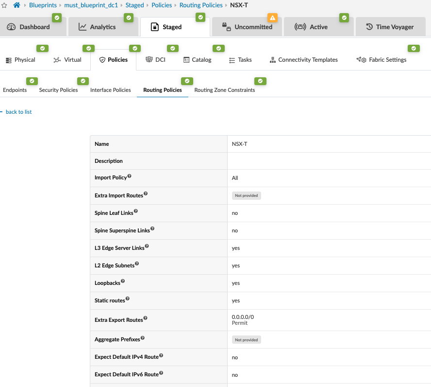
Juniper Apstra: Create a Routing Policy for NSX-T in the Blueprint
Add a Routing policy for the NSX-T routing zone created in the next step.
In the Juniper Apstra UI, navigate to Blueprints > <blueprint-name> > Staged > Policies > Routing Policies > Create Routing Policy.
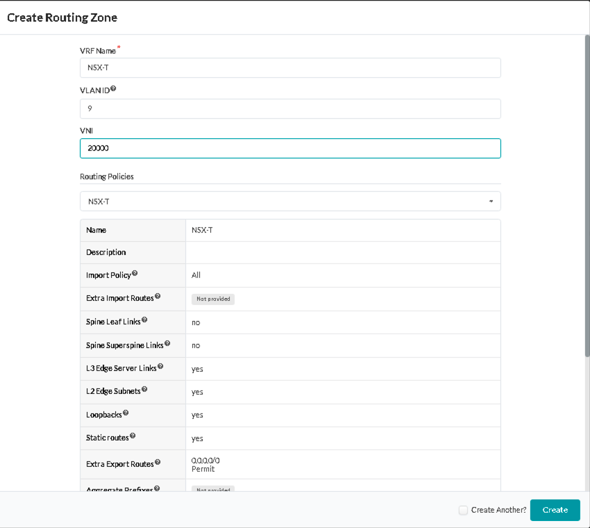
Juniper Apstra: Create a Routing Zone in the Blueprint
Add a Routing Zone That Maps to a VRF in the Blueprint:
- In the Juniper Apstra UI, navigate to Blueprints >
<blueprint-name>
> Staged > Virtual > Routing Zones > Create
Routing Zone and following details:
- VRF Name: NSX-T
- VLAN ID: 9
- VNI: 20000
- Route Target: 20000:1
- Routing Policies: NSX-T
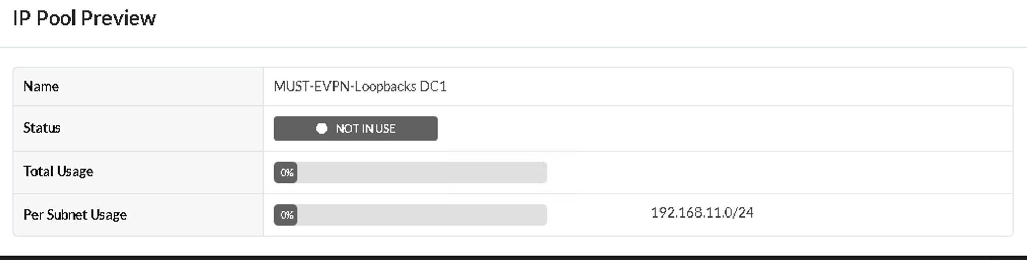
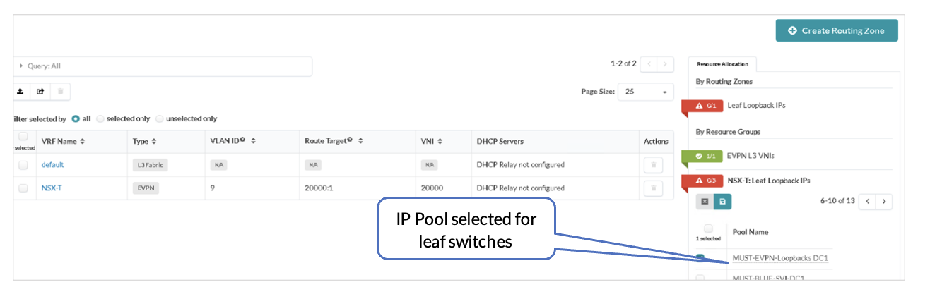
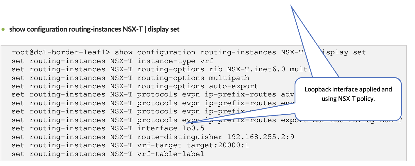
Juniper Apstra: Assign the Loopback IPs to the Routing Zone
After creating the NSX-T routing zone, assign the loopback IPs for the routing zone. The loopback IP is allocated from an IP Pool in Resources. In the following figures, the pool MUST-EVPN-Loopbacks DC1 is already created under Resources. This is as per the section Apstra Resources: ASN, Fabric, and Loopback IP Address.
The loopback IP is assigned to the routing instance and used to extend EVPN and the NSX-T overlay VLAN between the leaf switches.
Juniper Apstra: Add the NSX-Manager into the Blueprint
Add the NSX-Manager into the Blueprint that is managing the fabric:
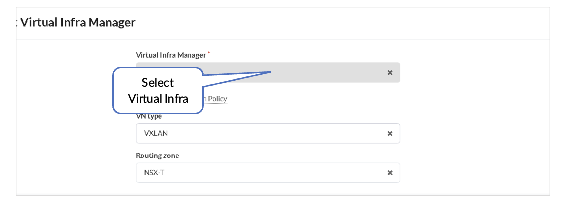
- In the Juniper Apstra UI navigate to Blueprints > <blueprint-name > > Staged > Virtual > Virtual Infra > Add Virtual Infra.
- From Virtual Infra Manager, select the vSphere added in Juniper Apstra: Add the NSX-Manager.
- Set the VLAN Remediation Policy VN Type as VXLAN.
- Set the Routing Zone as NSX-T.
Juniper Apstra: Add the NSX-T-Overlay as a VN
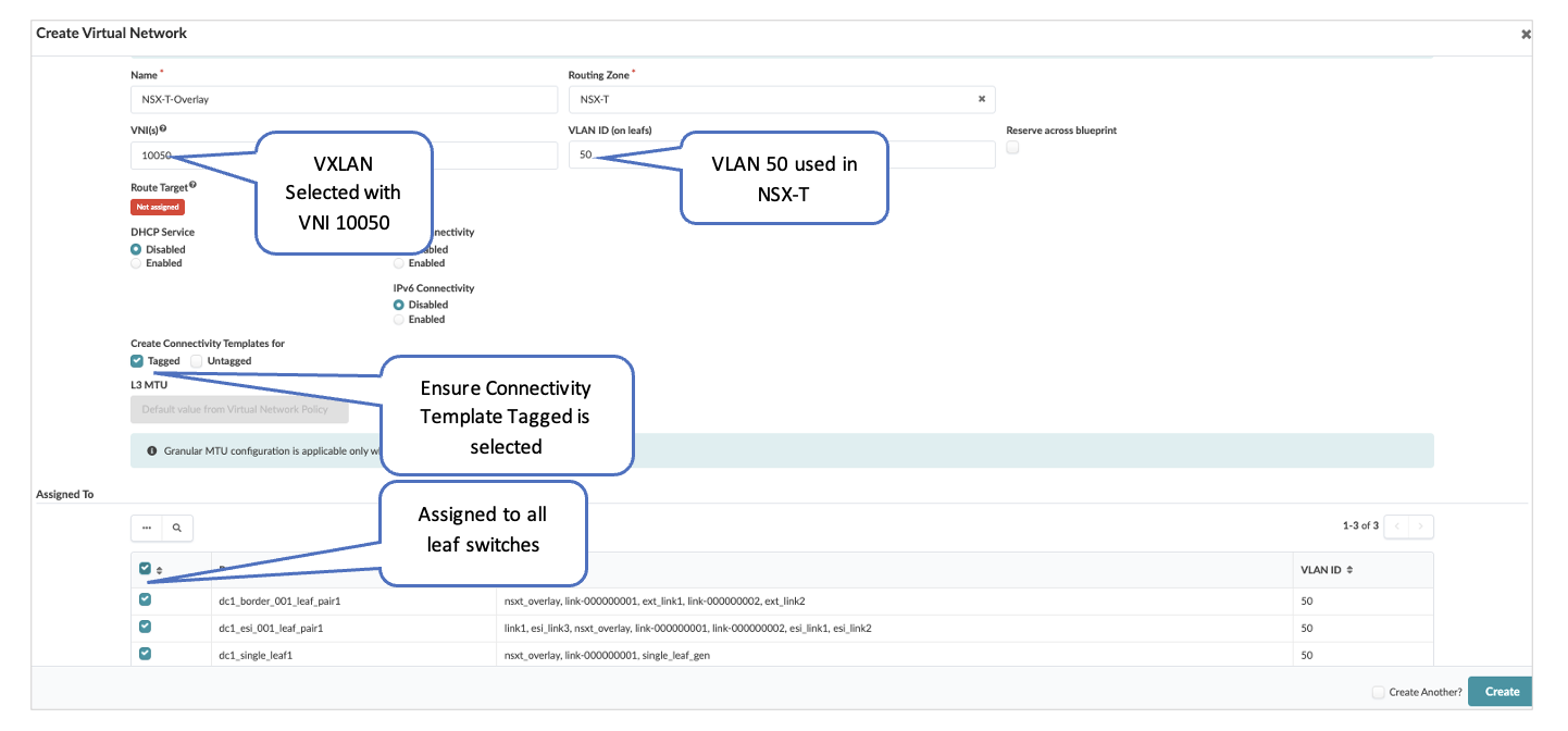
For the GENEVE Tunnels to come up between the Transport Nodes in NSX-T, connectivity needs to be established through Juniper Apstra Fabric. This is ensured by creating VXLAN Virtual Network in Apstra and assigning correct port mapping in ToR leaf switches towards Transport Node. Ensure that VLAN ID for Overlay VXLAN VN defined in Apstra match the one mapped in Overlay Profile in NSX-T for Transport Nodes.
VLAN 50 is configured in NSX-T Managed for Overlay, which maps to the VNI 10050. Connectivity Template Tagged should be selected while creating a virtual network. The virtual network is assigned to all leaf switches. The IPv4 subnet (IRB) is disabled as NSX-T is already assigning the TEPs to the hosts in NSX-T.
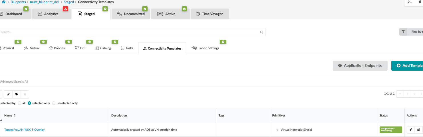
Juniper Apstra: Verify the Connectivity Templates
With the virtual network created, if you select Create Connectivity Templates, then a Connectivity Template type Virtual Network[Single] is created.
Verify the Creation of a Virtual Network:
- In the Juniper Apstra UI, navigate to Blueprints > <blueprint-name> > Staged > Connectivity Templates.
- Scroll to look for the connectivity template for the Virtual Network.
- Click Edit to view the connectivity template.
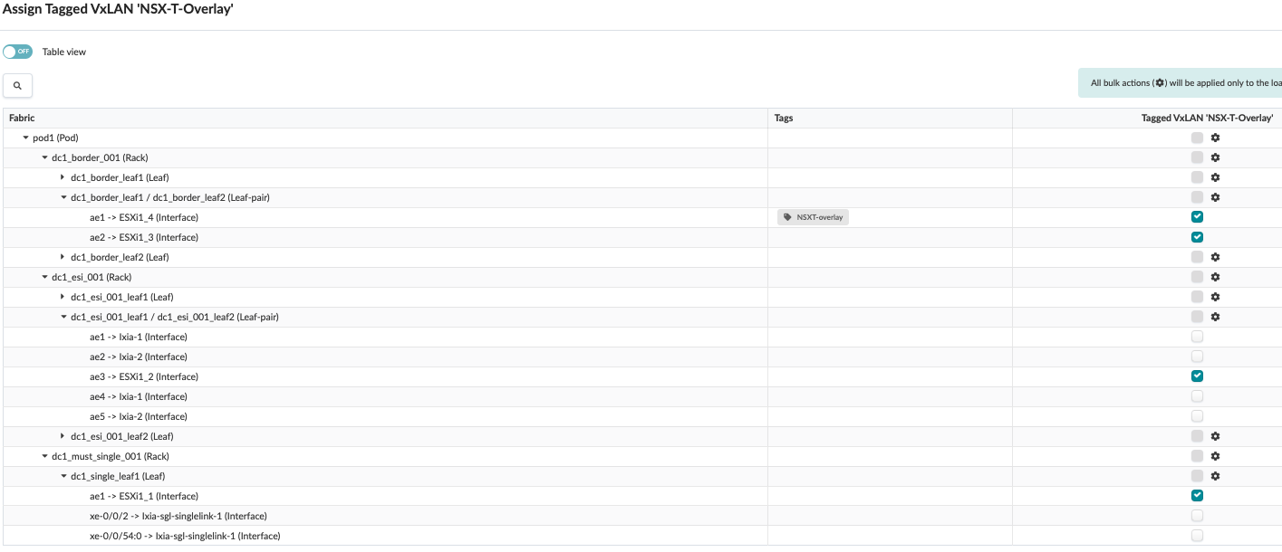
Juniper Apstra: Assign Interface to the Connectivity Templates
The connectivity template is assigned to the aggregate Ethernet (AE) interfaces facing the ESXi hosts.
Juniper Apstra: Commit the Configuration
From Blueprint, navigate to Blueprints > <blueprint-name> > Uncommitted and commit the configuration. This pushes the VN and routing zone to NSX-T to all the fabric devices.
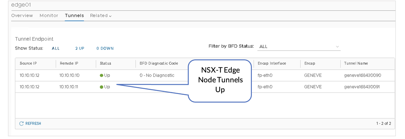
VMware NSX-T: GENEVE Tunnels
Once Juniper Apstra has pushed the configurations to the Junos OS devices, observe that the GENEVE tunnels between the Transport Nodes and the Edge Nodes are up:
- On the edge01 Edge-VM , view the Tunnel Endpoints and verify status is UP.
- In NSX-T Manager, navigate to NSX-T Manager > System > Fabric > Nodes > Edge Transport Nodes.
- Click edge01, then click Tunnels.
Juniper Apstra: Add Connectivity Templates for Connectivity from Edge Node to the Fabric
The connectivity templates specify the IP link for the connectivity from the Edge Node to the fabric and the BGP peering session with a user-specified BGP neighbor-addressed peer.
- In the Juniper Apstra UI, navigate to Blueprints > <blueprint-name> > Staged > Connectivity Templates.
- Click Add Template.
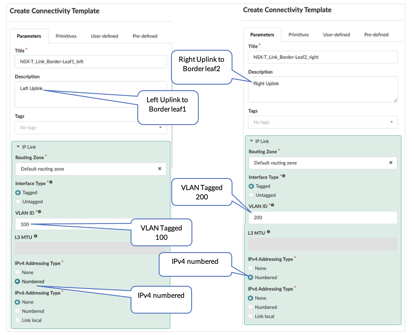
Juniper Apstra: Add IP Link, BGP Peering and Static Route
A Connectivity template is used to create the NSX-T uplinks towards NSX-T Edge Node edge01 for both left and right uplinks.
Here, the default routing zone is selected to connect to the Edge Nodes as the NSX-T traffic within the fabric is an overlay traffic. Once the traffic reaches NSX-T, it is an underlay traffic.
The peer ASN is the NSX-T T0-1 ASN 65000.
- Create Two IP Link Connectivity Templates for Left Uplink and Right Uplink
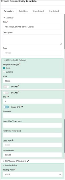
- Create BGP Peering and Assign NSX-T Routing Policy
- In the Juniper Apstra UI, navigate to Blueprints > <blueprint-name> > Staged > Connectivity Templates.
- Click Add Template.
- Create Connectivity Templates for BGP peering and assign the NSX-T routing policy.
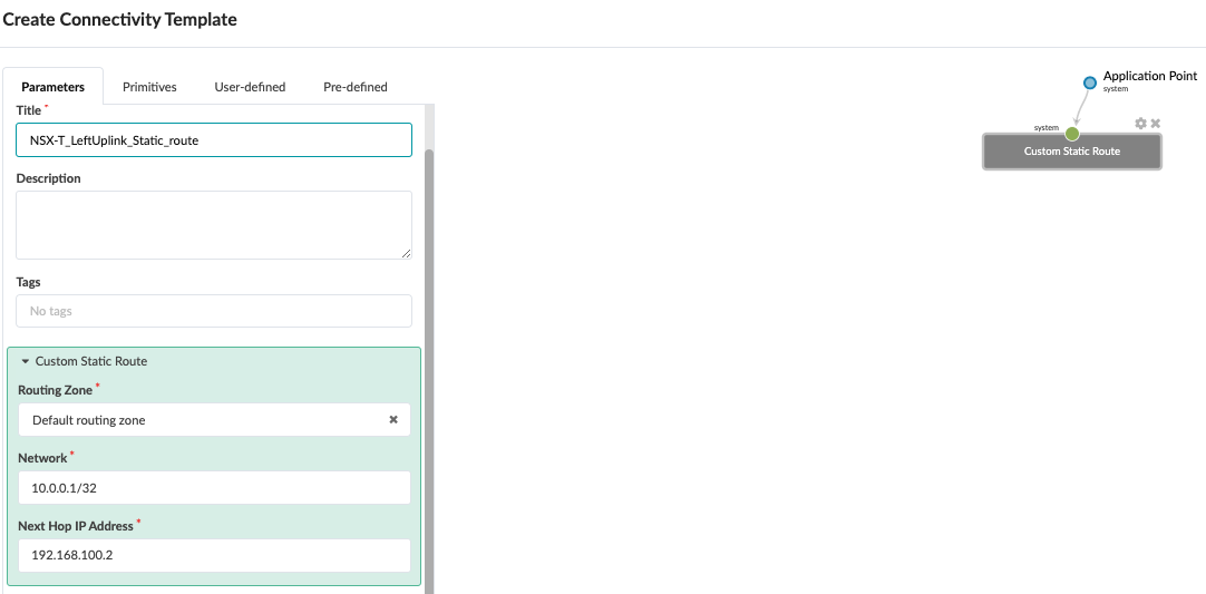
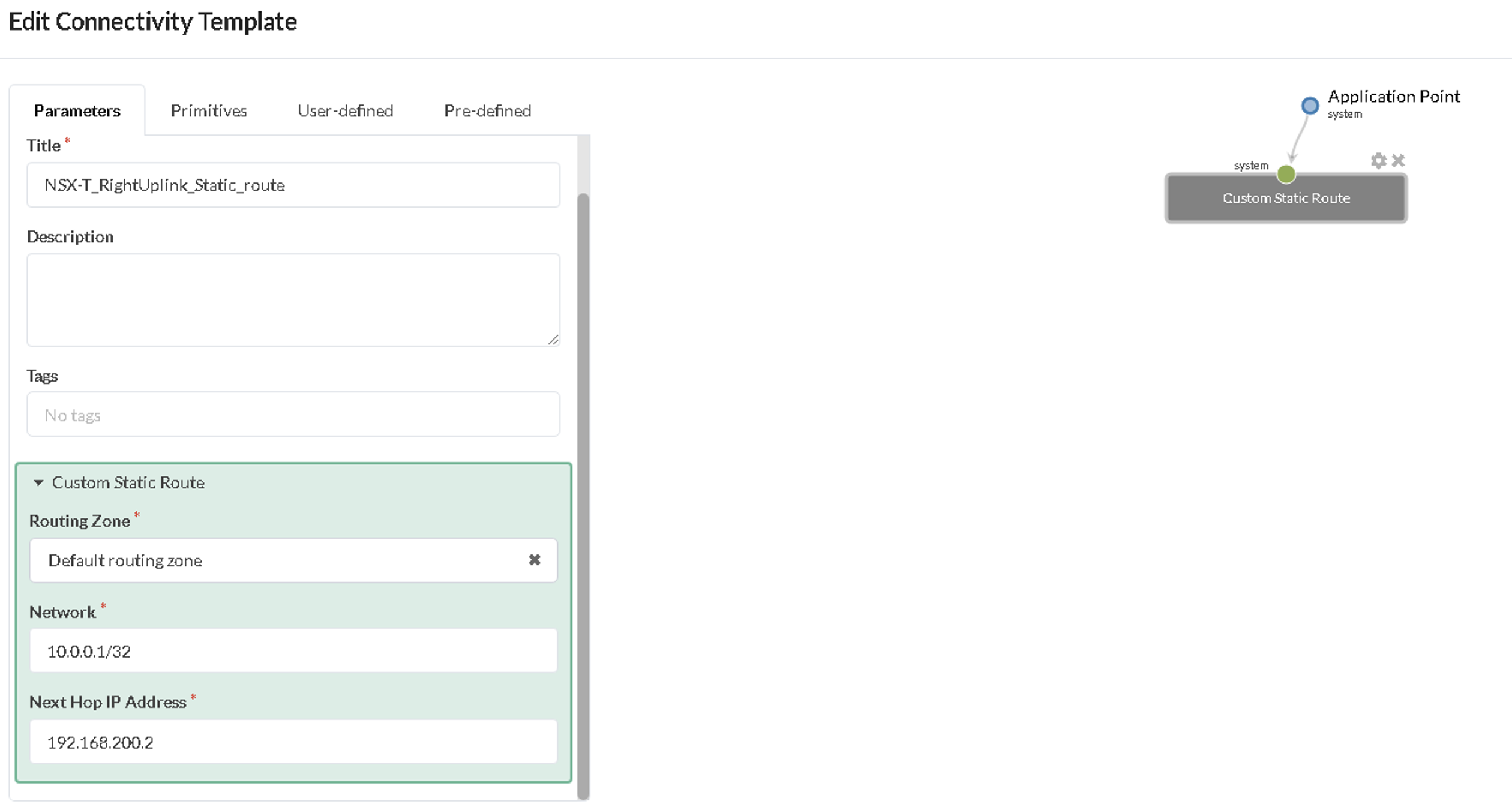
- Create Two Custom Static Route Connectivity Templates
The static route is created in a separate Connectivity Template as the primitive ‘Custom Static Route’ used here is generated at the system level (border-leaf level). The static route for the left uplink starts from Border Leaf1 to the Edge Node and for the right uplink from Border Leaf2 to the Edge Node.
- In the Juniper Apstra UI, navigate to Blueprints > <blueprint-name> > Staged > Connectivity Templates.
- Click Add Template. Repeat this process to create Connectivity Templates for the left and right uplinks.
-
Create Two Connectivity Templates for Static Route
- Left static route from the Border Leaf1 to the Edge Node.
- Right static route from the Border Leaf2 to the Edge Node.
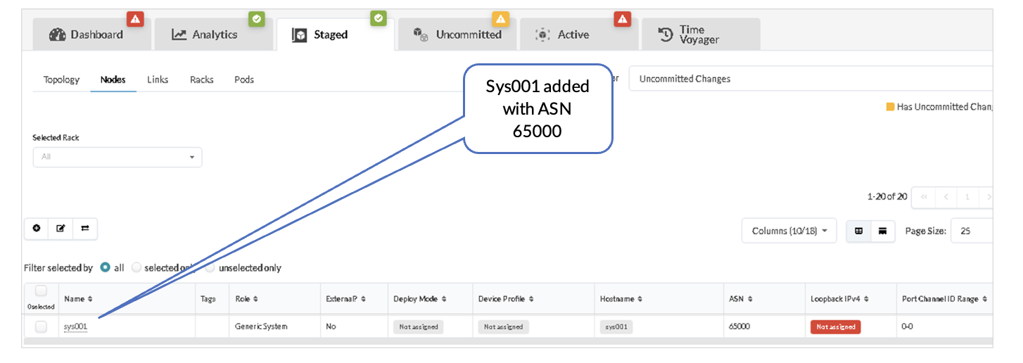
Juniper Apstra: Renaming the Generic System and Adding Links from Border Leaf switches
Once the connectivity template for IP_Link is created for the uplink from the Border leaf switches towards the NSX-T-Edge device, Apstra adds a generic system node with the ASN (65000 is allocated to T0 in the earlier steps).
- In the Juniper Apstra UI, navigate to Blueprints > <blueprint-name> > Staged > Physical > Nodes.
- Locate the generic system added as shown below. Click the pencil icon to change this name to NSXT-Edge-01.
After changing the generic system name, create links from both border leaf switches towards ESXi for the left and right uplink.
- In the Juniper Apstra UI, navigate to Blueprints > <blueprint-name> > Staged > Physical > Topology.
- Select Border leaf1, then select ‘Add links to a generic system’ and create a link from dc1_border_leaf1.
- For dc1_border_leaf2, the steps to create the right uplink link are similar.
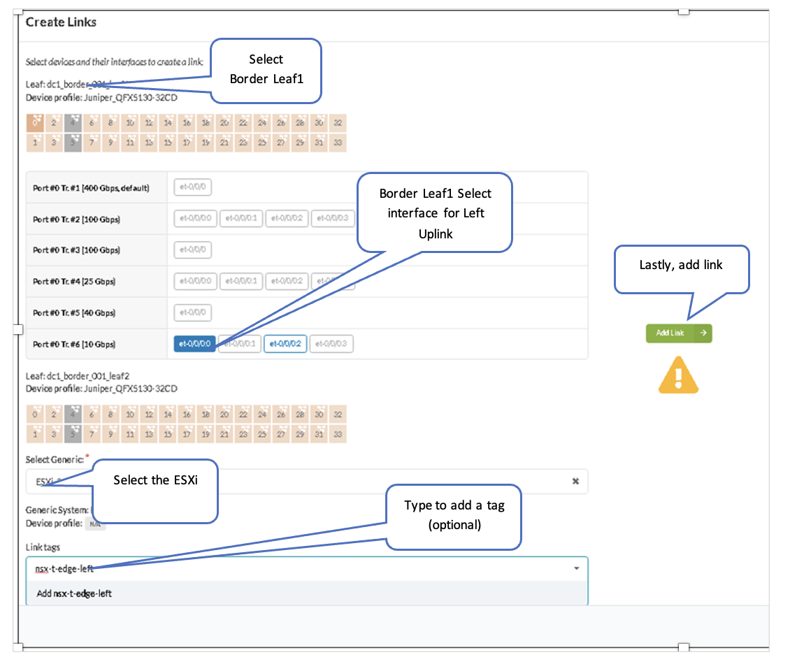
Once both border leaf switches uplinks are created, the links are shown on the topology. After this, interfaces can be assigned from the connectivity templates, as covered in the next steps.
Juniper Apstra: Assign the Interfaces to the Connectivity Template
Assign connectivity templates created in Juniper Apstra: Add IP Link, BGP Peering and Static Route section.
- Assign Uplinks.
- For Uplinks from the border leaf switches, assign the appropriate ethernet interface
for dc1_border_leaf1 and dc1_border_leaf2:
- Left uplink from dc1_border_leaf1
Figure 79: Left Uplink Interface on Border Leaf1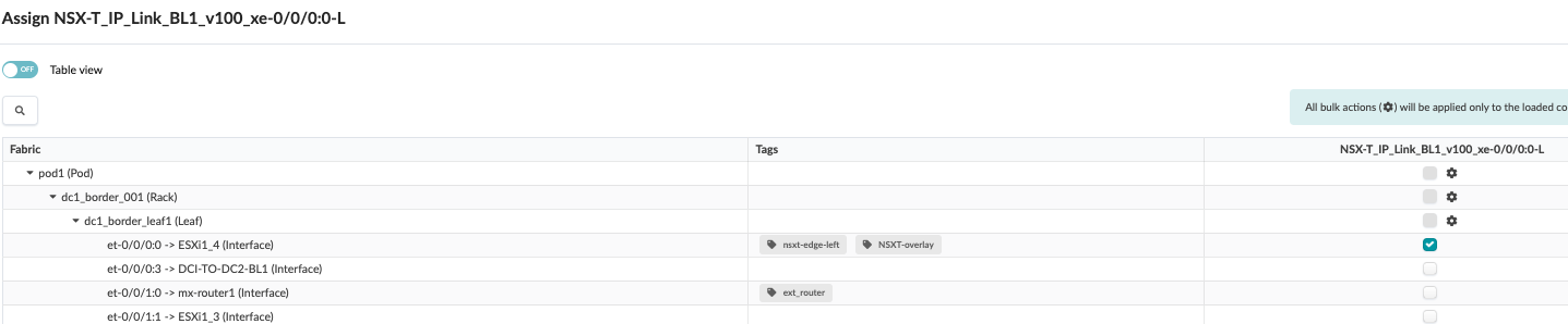
- Right uplink from dc1_border_leaf2
Figure 80: Right Uplink interface on Border Leaf2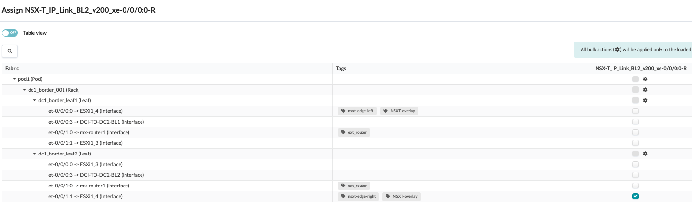
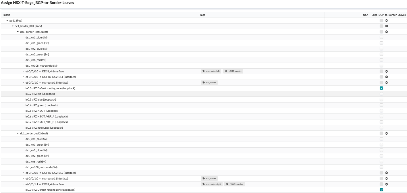
- Assign BGP.
- For BGP peering, select dc1_border_leaf1 and dc1_border_leaf2 loopback Interfaces lo0.0.
Figure 81: Assign BGP Peering to Both Border Leaf switches Default Loopback Interface for Left and Right Uplink
- Assign Static Routes
- Static route for left uplink to Border Leaf1
Figure 82: Assign Static Route for Left Uplink to Border Leaf1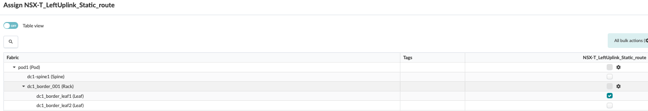
- Static route for right uplink to Border Leaf2
Figure 83: Assign Static Route for Right Uplink to Border Leaf2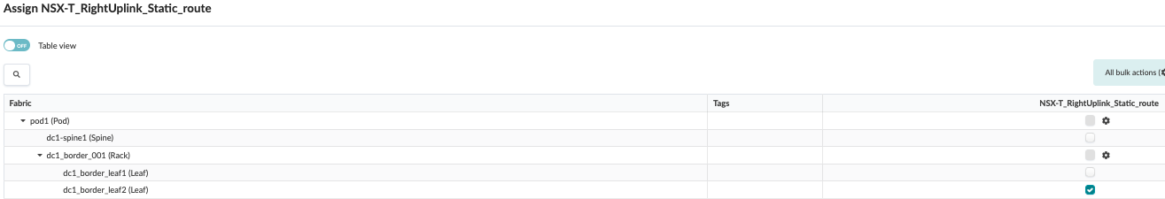
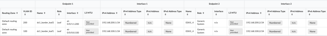
Juniper Apstra: Assign the IPs and VLAN IDs to the Interfaces
Now that a Connectivity Template has been created and physical interfaces are assigned, you must assign IP addresses and VLAN IDs to the interfaces.
Edit the Interface connecting the Border Leaf and the Edge Node:
- In the Juniper Apstra UI, navigate to Blueprints > <blueprint-name> > Staged > Virtual > Routing Zones > Default Routing Zone > Interfaces > Edit IP Addresses.
- Enter the IP address for Border Leaf switches and the IP address of the Edge node interfaces on the host.
Juniper Apstra: Commit the Configuration
Navigate to Blueprints > Uncommitted and commit the configuration. This pushes all the uplinks created using connectivity templates to the devices.
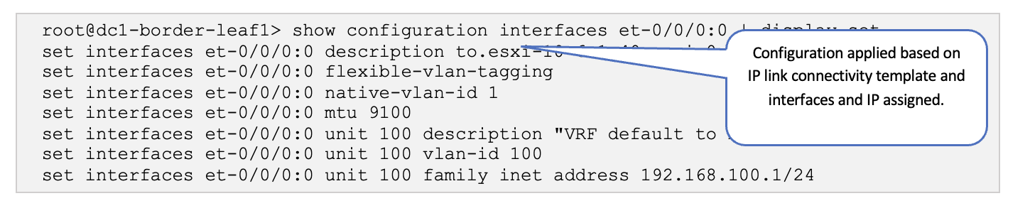
Juniper Junos OS: Verify Configs
Log onto one of the Border Leaf switches and verify that the configuration is being pushed.
Verify Physical Fabric Configuration
SSH into one of the Border Leaf switches and run the following commands:
-
show configuration interfaces et-0/0/0:0 | display set
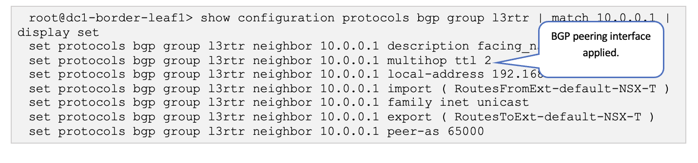
-
show configuration protocols bgp group l3rtr | match 10.0.0.1 | display set
-
show configuration routing-options | display set
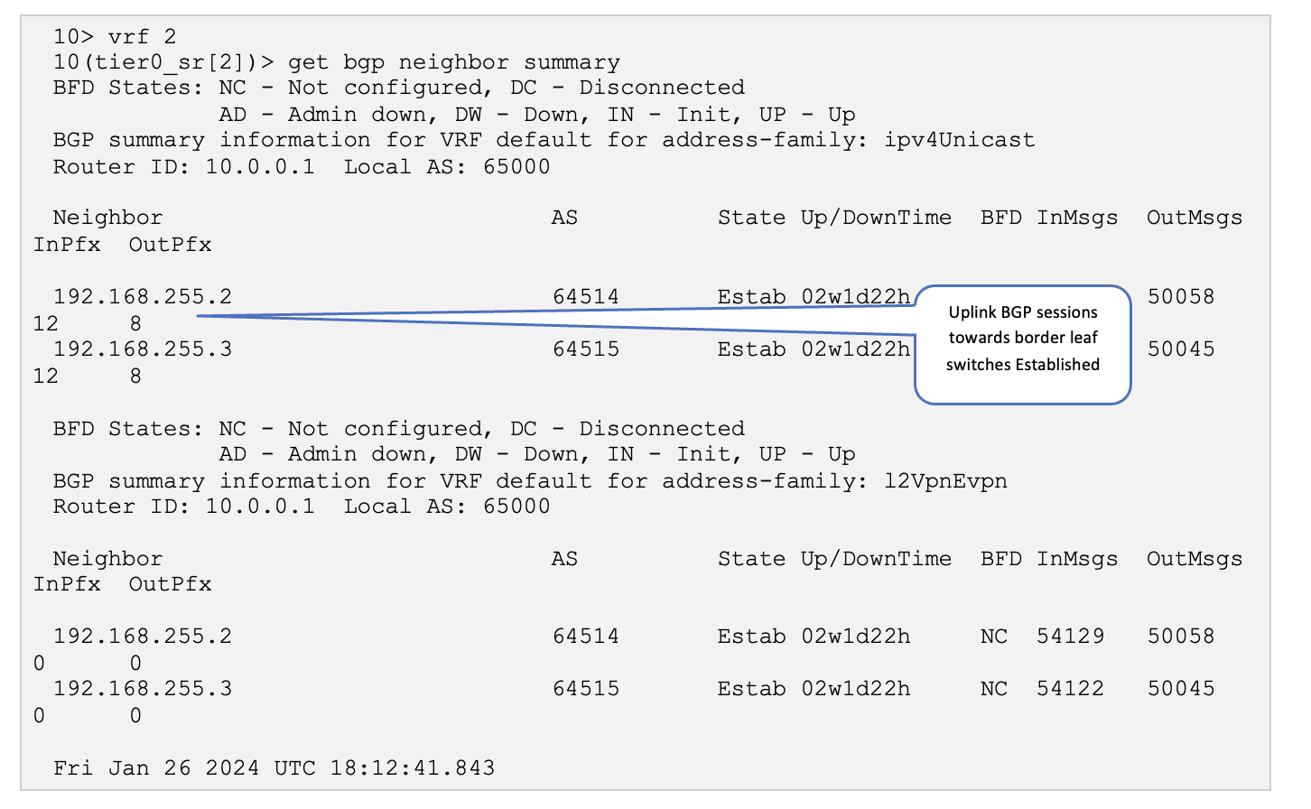
VMware NSX-T: Verify BGP Session on Edge
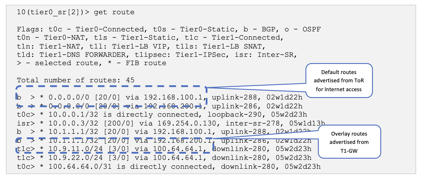
On the Edge Node, verify that the BGP sessions are established, and the overlay routes exchanged.
Verify NSX-T Configuration
SSH into the NSX-T edge01 Edge-VM and run the following commands:
- Firstly, to determine the VRF (SR-T0-1), run the command, get
logical-router and pick the one that has the name
“SR-T0-1”. (service router Tier0) The corresponding VRF
number is in the VRF column.
10> get logical-routers
Fri Jan 26 2024 UTC 18:11:32.003
Logical Router
UUID                                   VRF    LR-ID  Name                              Type                        Ports   Neighbors
736a80e3-23f6-5a2d-81d6-bbefb2786666   0      0                                        TUNNEL                      3       6/5000
c9b6e428-86e8-457a-b961-574e4222d62b   1      17     DR-T0-1                           DISTRIBUTED_ROUTER_TIER0    5       2/50000
5e7295b5-9370-4dcc-bfda-5c5d8c43a997   2      8193   SR-T0-1                           SERVICE_ROUTER_TIER0        9       3/50000
3468dc14-32f1-423c-ac4c-ebf9835deffd   4      8199   SR-VRF-VRF-B                      VRF_SERVICE_ROUTER_TIER0    5       0/50000
bb12844c-e93e-434c-a8a8-bc41f0a97559   5      2060   DR-VRF-VRF-B                      VRF_DISTRIBUTED_ROUTER_TIER0 4       0/50000
dbbb8e77-02c2-496b-b9f7-d14b95c360cd   6      8198   SR-VRF-VRF-A                      VRF_SERVICE_ROUTER_TIER0    6       0/50000
8f4fad8c-bb61-4b17-8772-7b1797f599eb   7      2058   DR-VRF-VRF-A                      VRF_DISTRIBUTED_ROUTER_TIER0 3       0/50000
d686dc86-3101-493f-9e21-65f94e45f73b   8      16     DR-T1-1                           DISTRIBUTED_ROUTER_TIER1    5       0/50000
9e796408-7732-4fdc-9de6-2d286572f89b   9      1025   SR-T1-1                           SERVICE_ROUTER_TIER1        5       2/50000
-
get bgp neighbor summary
-
get route
VMware NSX-T: Verify BGP Session on ToR
Juniper Apstra should detect the no BGP anomaly on the blueprint.
In the Juniper Apstra UI, navigate to Blueprints > <Blueprint-name> > Active.
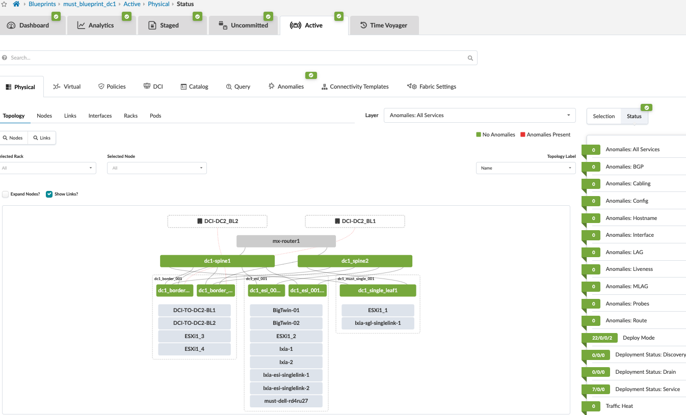
Log onto one of the border leaf switches and verify that the BGP sessions are up, and the overlay routes are exchanged.
Verify Physical Fabric Configuration
SSH into one of the border leaf switches and run the following commands:
-
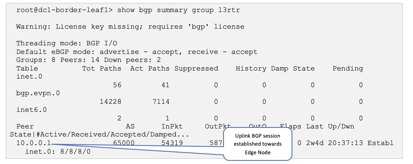
show bgp summary group l3rtr
-
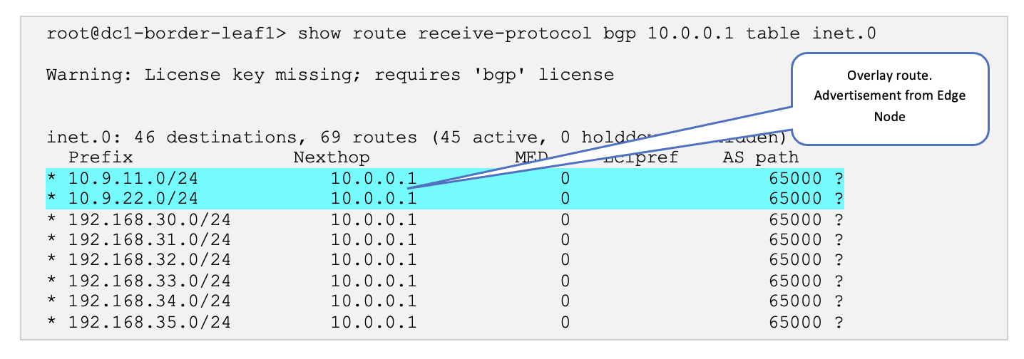
show route receive-protocol bgp 10.0.0.1 table inet.0
-
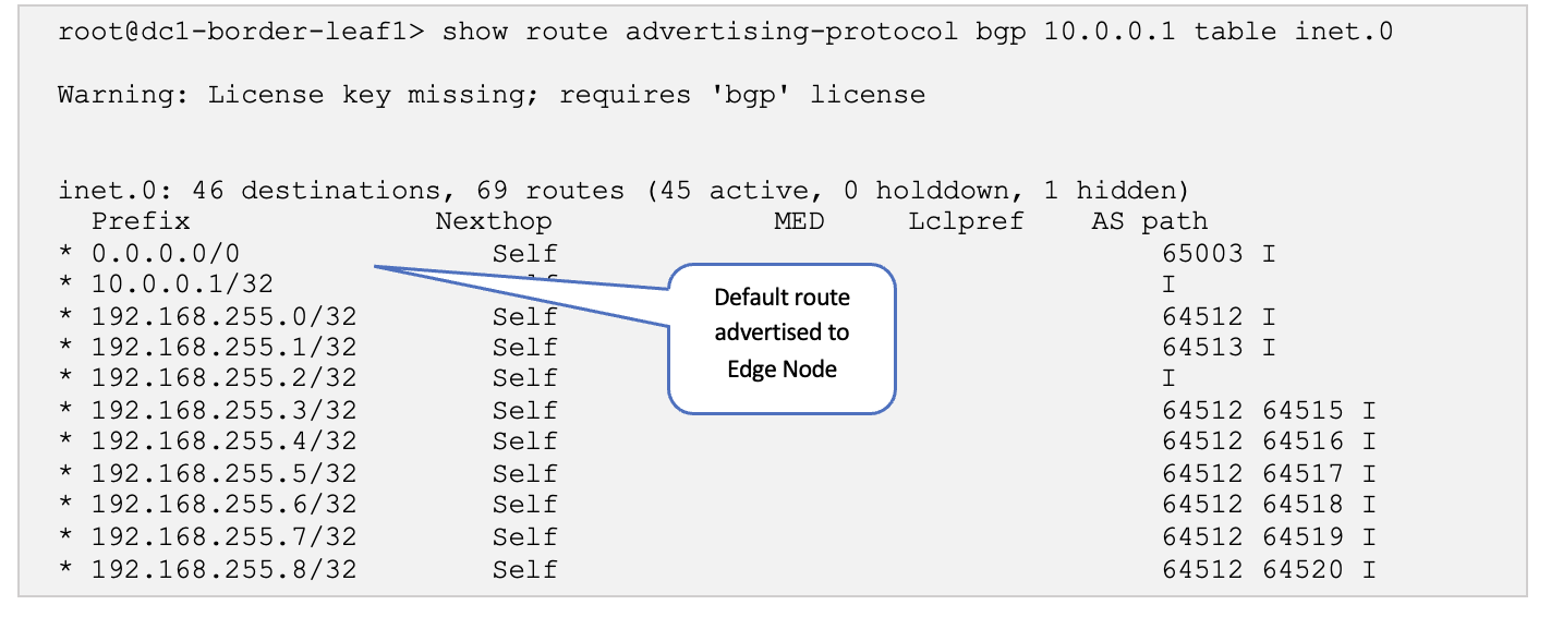
show route advertising-protocol bgp 10.0.0.1 table inet.0
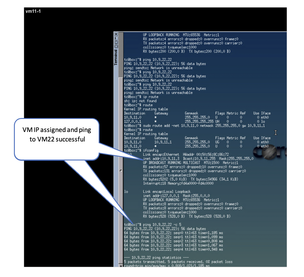
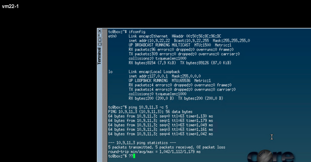
VMware NSX-T: Verify Overlay Connectivity (East-West)
To test east-west traffic, run ping tests between the VMs across segments and between the Linux VMs created in VMware vSphere: Create VMs in the Segments.
Following is the flow shown in Figure 86:
- The ping from VM11-1 (on ESXi1_2 host) traverses the Fabric from ESI leaf to reach Border Leaf1.
- From border-leaf, it’s sent towards the Edge nodes hosted on ESXi1_4.
- From Edge node the traffic is sent towards T1-GW which in turn sends the ping traffic using the TEP port on ESXi1_4 to reach TEP port of ESXi1_3, which then reaches the VM22-1.
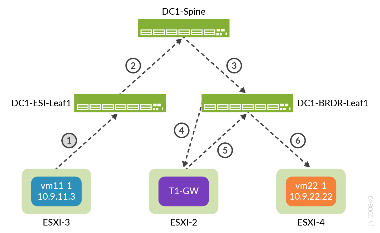
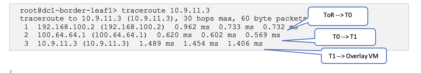
Traceroute to the overlay VMs from the Border Leaf Switches shows the path taken.
(Optional) Juniper Apstra: Adding vSphere Server to Juniper Apstra
This step is optional, but the integration of vSphere provides an added layer of visibility into MACs, VMs, and ARPs. It also enables you to view all underlying VMs and docker containers connected with each fabric leaf device connected through the ESXi server.
Add the vSphere server into the blueprint that is managing the fabric:
- In the Juniper Apstra UI, navigate to Blueprints > <blueprint-name> > Staged > Virtual > Virtual Infra > Add Virtual Infra.
- Set the VLAN Remediation Policy VN Type to VXLAN.
- Set the Routing Zone to NSX-T.
- Navigate to Blueprints > <blueprint-name> > Active > Query. All the VMs associated with the fabric can be viewed here. For more information, refer to the Juniper Apstra 4.2 User Guide.