Configure a WAN Edge Template
Streamline your configuration process by creating templates for your WAN Edge devices. For even quicker configuration, use pre-defined, device-specific templates.
By using WAN Edge templates, you can define common spoke characteristics such as WAN interfaces, traffic-steering rules, and access policies. When you assign a template to a site, Juniper Mist sends the configuration to the devices. When changes are needed, simply change the template, and all devices receive the new configurations. With this process you can easily configure and manage a large number of devices while ensuring consistency across your network infrastructure.
For hub-and-spoke configurations, you use WAN Edge templates to configure WAN Edge devices at spoke sites. You use hub profiles to configure WAN Edge devices at hub sites.
Before You Begin
Create a WAN Edge Template By Defining Your Own Settings
Create a template to define common spoke characteristics that you want to deploy across your organization. Associate templates with sites, and then onboard devices to sites. When onboarded, each device automatically gets the configuration from the associated template.
To configure a WAN Edge template:
-
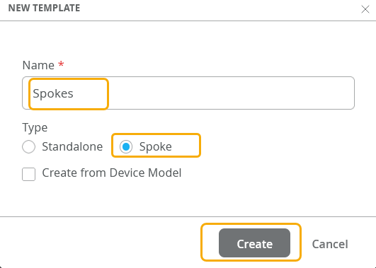
In the New Template window, enter a name for the template (up to 64
characters), click Spoke for the type, and then click
Create.
-
Work your way through the remaining sections of the template, saving your
work as you go.
Tips:
-
When a configuration panel appears at the side of the screen, enter the settings, and then click the Add or Save button at the bottom of the panel.
If you click a button in a panel and a new sub-section opens, enter the settings, and then click the check mark in the title bar of the sub-section.

In fields with a VAR label, you can enter variables to represent values such as IP addresses, VLAN IDs, and more. As you type, the field displays any matching variables as defined in site configurations across the organization.

For more information, see Use Site Variables to Streamline Configuration.
-
After completing each major section of a template, click Save at the top-right corner of the template page. When the page reloads, showing the list of templates, simply click the template to resume your work.
-
For help with the various sections of the template, see the Configuration Reference chapter of this guide.
-
Create a Template with Pre-Defined Device-Specific Settings
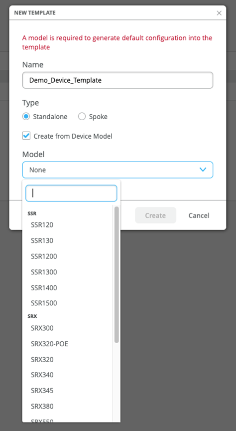
Create a template with predefined, device-specific settings to apply standard configurations for Juniper devices.
These templates are unique for each device model. After you name your template and select the device model, no additional input is needed.
The WAN Edge device specific templates provide basic network configuration in a single step. Templates also allow for re-usable and consistent configuration across your WAN Edge devices. The template provides device-specific, preconfigured WAN interfaces, LAN interfaces, a traffic steering policy, and an application policy. All you have to do is name the template and select the device type.
For example, SSR120 WAN Edge template generates several values, including Ethernet interfaces for LAN and WAN with relevant DHCP and IP values:
- wan ge-0/0/0
- wan2 ge-0/0/1
- wan3 ge-0/0/2
- lan ge-0/0/3
To select a device-specific WAN Edge template:
-
Select your device model.