Introduction to EVPN LAG Multihoming
Ethernet link aggregation remains a vital technology in modern data center networking. Link aggregation provides the technology to bundle interfaces and to increase bandwidth in a data center by adding new links to bundled interfaces. Link aggregation can significantly increase a network’s high availability by providing a redundant path or paths that traffic can utilize in the event of a link failure and has a variety of other applications that remain highly relevant in modern data center networks.
New EVPN technology standards—including RFCs 8365, 7432, and 7348—introduce the concept of link aggregation in EVPNs through the use of Ethernet segments. Ethernet segments in an EVPN collect links into a bundle and assign a number—called the Ethernet segment ID (ESI)—to the bundled links. Links from multiple standalone nodes can be assigned into the same ESI, introducing an important link aggregation feature that introduces node level redundancy to devices in an EVPN-VXLAN network. The bundled links that are numbered with an ESI are often referred to as ESI LAGs or EVPN LAGs. The EVPN LAGs term will be used to refer to these link bundles for the remainder of this document.
Layer 2 Multihoming in EVPN networks is dependent on EVPN LAGs. EVPN LAGs, which provide full active-active link support, are also frequently enabled with LACP to ensure multivendor support for devices accessing the data center. Layer 2 Multihoming with LACP is an especially attractive configuration option when deploying servers because the multihoming is transparent from the server point of view; the server thinks it is connected to a single networking device when it is connected to two or more switches.
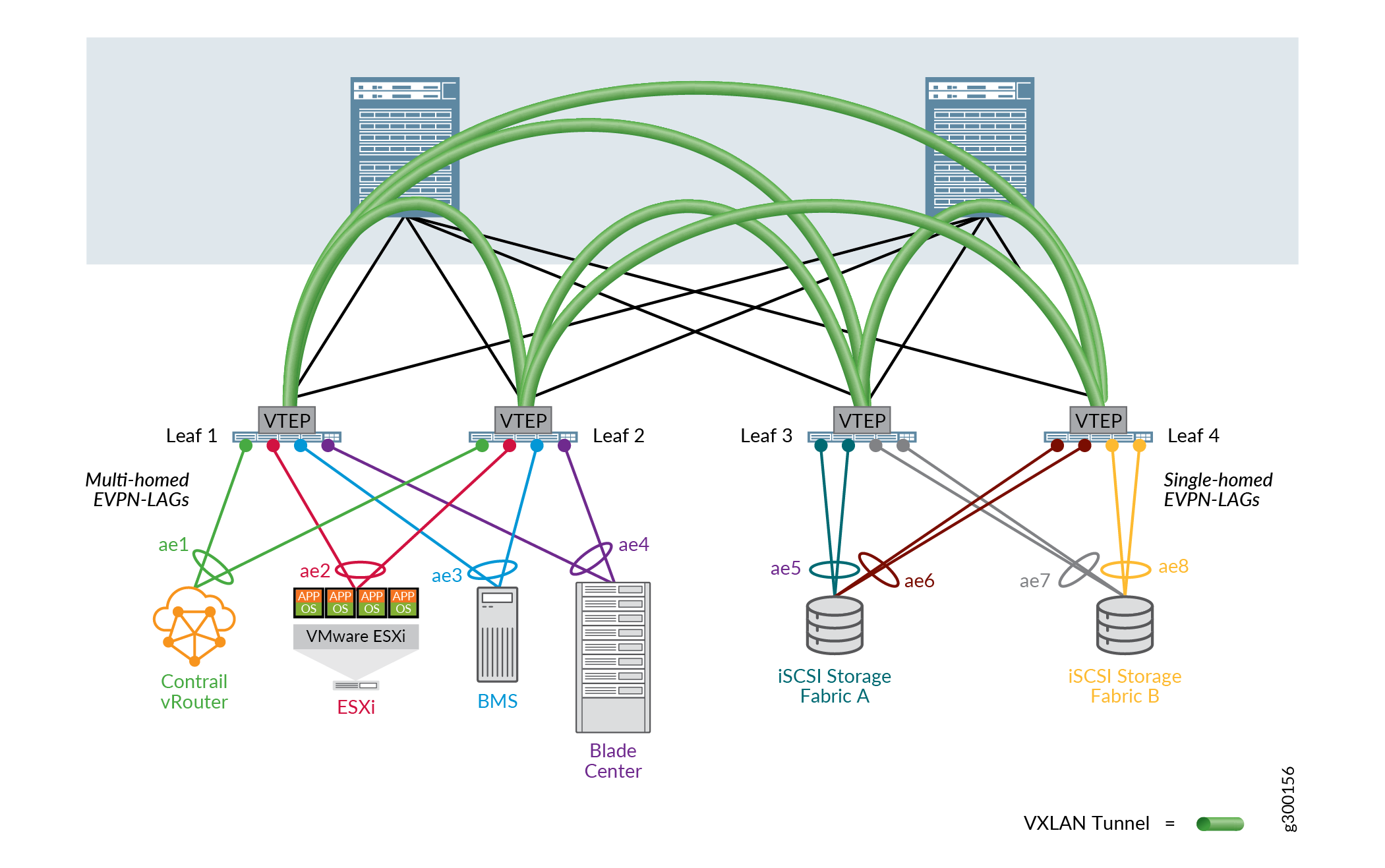
Figure 1 shows a fabric topology representing a standard 3 stage spine-leaf underlay architecture. An EVPN-VXLAN overlay offers link and node level redundancy and an active-active Layer 2 Ethernet extension between the leaf devices, without the need to implement a Spanning Tree Protocol (STP) to avoid loops. Different workloads in the data center are integrated into the fabric without any prerequisites at the storage system level. This setup would typically use QFX5110 or QFX5120 switches as leaf devices and QFX10002 or QFX10008 switches as spine devices.

Single-homed end systems are still frequently used in modern data center networks. The iSCSi storage array systems in the figure provide an example of single-homed end systems in an EVPN-VXLAN data center.
See the EVPN Multihoming Implementation section of the EVPN Multihoming Overview document for additional information related to ESIs and ESI numbering. See Multihoming an Ethernet-Connected End System Design and Implementation in the Cloud Data Center Architecture Guide for a step-by-step configuration procedure of an EVPN LAG implementation.
