Advanced Security and Data Center Interconnect Configurations
Use these examples to configure advanced security and DCI on your collapsed spine data center architecture.
Configure Advanced Security for Inter-Tenant Traffic
The SRX Series is a next-generation firewall that can provide advanced security services for inter-tenant traffic. Use this section to route inter-tenant traffic between JNPR_1 and JNPR_2 in DC1 through the SRX chassis cluster.
Requirements
The devices that you configured in How to Configure a Collapsed Spine with EVPN Multihoming.
The SRX chassis cluster must already be configured and running. See Configuring Chassis Clustering on SRX Series Devices for details about enabling a SRX chassis cluster.
Overview
The SRX Series Firewalls in your chassis cluster operate as a single device to provide device, interface, and service-level redundancy. Use this section to separate the chassis cluster into zones and configure the routing policies so that the correct traffic is routed through the security devices.
Topology
Both spine switches are physically connected to both SRX nodes as shown in Figure 1.

This example is based on SRX345 devices. Once placed into a HA cluster, the interfaces on node 1 are associated with FPC slot 5. This means the ge-0/0/11 interface shown for node 1 is actually configured as ge-5-0/11 once the cluster is formed. The FPC number for node 1 in a HA cluster can vary by SRX model type.
Reth1 is a logical interface in the SRX cluster. It is active on one of the nodes of the SRX cluster. If the primary node or interconnect link between the SRX devices and the spine switches fails, Reth1 will failover to the secondary node. Figure 2 shows the logical interfaces between the SRX devices and the spine switches.

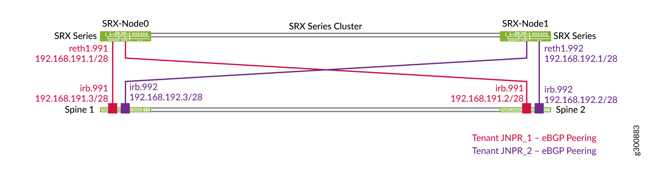
Each spine switch establishes separate EBGP peerings with the SRX cluster in each routing instance or tenant as shown in Figure 3. For example, Spine 1 has two peerings with the SRX cluster, one in each routing instance: JNPR_1 and JNPR_2. Reth1.991 peers with the JNPR_1 routing instance on the spine switches and belongs to the JNPR_1 security zone. Reth1.992 peers with the JNPR_2 routing instance on the spine switches and belongs to the JNPR_2 security zone.
The SRX Series Firewall advertises a summary route that covers all prefixes (for example, 192.168.0.0/16). The spine switches advertise specific subnets in each routing instance.
Configure the Interfaces
Configure the SRX Device
Step-by-Step Procedure
Configure the group for the logical interfaces on the SRX device.
set chassis cluster reth-count 3
set chassis cluster redundancy-group 0 node 0 priority 100
set chassis cluster redundancy-group 0 node 1 priority 1
set chassis cluster redundancy-group 1 node 0 priority 200
set chassis cluster redundancy-group 1 node 1 priority 100
set chassis cluster redundancy-group 1 preempt
set chassis cluster redundancy-group 1 interface-monitor ge-0/0/11 weight 255
set chassis cluster redundancy-group 1 interface-monitor ge-0/0/12 weight 255
set chassis cluster redundancy-group 1 interface-monitor ge-5/0/11 weight 255
set chassis cluster redundancy-group 1 interface-monitor ge-5/0/12 weight 255
Configure the logical interfaces. Reth1 is a tagged Layer 3 interface on the SRX cluster. Reth1.991 peers with the JNPR_1 routing instance on the spine switches. Reth1.992 peers with the JNPR_2 routing instance on the spine switches.
set interfaces reth1 vlan-tagging
set interfaces reth1 redundant-ether-options redundancy-group 1
set interfaces reth1 redundant-ether-options lacp active
set interfaces reth1 redundant-ether-options lacp periodic fast
set interfaces reth1 unit 991 description "Spine Interconnect for JNPR_1"
set interfaces reth1 unit 991 vlan-id 991
set interfaces reth1 unit 991 family inet address 192.168.191.1/28

set interfaces reth1 unit 992 description "Spine Interconnect for JNPR_2"
set interfaces reth1 unit 992 vlan-id 992
set interfaces reth1 unit 992 family inet address 192.168.192.1/28

set interfaces ge-0/0/11 description "To Spine1 | ge-0/0/10"
set interfaces ge-0/0/11 gigether-options no-auto-negotiation
set interfaces ge-0/0/11 gigether-options redundant-parent reth1

set interfaces ge-5/0/11 description "To Spine1 | ge-0/0/11"
set interfaces ge-5/0/11 gigether-options no-auto-negotiation
set interfaces ge-5/0/11 gigether-options redundant-parent reth1

set interfaces ge-0/0/12 description "To Spine2 | ge-0/0/10"
set interfaces ge-0/0/12 gigether-options no-auto-negotiation
set interfaces ge-0/0/12 gigether-options redundant-parent reth1

set interfaces ge-5/0/12 description "To Spine2 | ge-0/0/11"
set interfaces ge-5/0/12 gigether-options no-auto-negotiation
set interfaces ge-5/0/12 gigether-options redundant-parent reth1
Place the logical interfaces into separate security zones. Reth1.991 belongs in the JNPR_1 security zone and Reth1.992 belongs in the JNPR_2 security zone.
set security zones security-zone JNPR_1-Zone host-inbound-traffic system-services ping
set security zones security-zone JNPR_1-Zone host-inbound-traffic protocols bgp
set security zones security-zone JNPR_1-Zone interfaces reth1.991

set security zones security-zone JNPR_2-Zone host-inbound-traffic system-services ping
set security zones security-zone JNPR_2-Zone host-inbound-traffic protocols bgp
set security zones security-zone JNPR_2-Zone interfaces reth1.992
Check the status of the chassis cluster.
user@srx1> show chassis cluster status
Monitor Failure codes:
    CS  Cold Sync monitoring        FL  Fabric Connection monitoring
    GR  GRES monitoring             HW  Hardware monitoring
    IF  Interface monitoring        IP  IP monitoring
    LB  Loopback monitoring         MB  Mbuf monitoring
    NH  Nexthop monitoring          NP  NPC monitoring
    SP  SPU monitoring              SM  Schedule monitoring
    CF  Config Sync monitoring      RE  Relinquish monitoring

Cluster ID: 1
Node   Priority Status               Preempt Manual   Monitor-failures

Redundancy group: 0 , Failover count: 1
node0  100      primary              no      no       None
node1  1        secondary            no      no       None

Redundancy group: 1 , Failover count: 5
node0  200      primary              yes     no       None
node1  100      secondary            yes     no       None
Configure Spine 1
Step-by-Step Procedure
Configure the SRX Series Firewall interconnected interfaces on Spine 1.
set interfaces ge-0/0/10 ether-options 802.3ad ae11
set interfaces ge-0/0/11 ether-options 802.3ad ae12

set interfaces ae11 description "to SRX Cluster | SRX-0"
set interfaces ae11 mtu 9216
set interfaces ae11 esi 00:00:00:00:00:00:00:00:01:11
set interfaces ae11 esi all-active
set interfaces ae11 aggregated-ether-options lacp active
set interfaces ae11 aggregated-ether-options lacp periodic fast
set interfaces ae11 aggregated-ether-options lacp system-id 00:00:00:00:01:11
set interfaces ae11 unit 0 family ethernet-switching interface-mode trunk
set interfaces ae11 unit 0 family ethernet-switching vlan members VLAN-991

set interfaces ae12 description "to SRX Cluster | SRX-1"
set interfaces ae12 mtu 9216
set interfaces ae12 esi 00:00:00:00:00:00:00:00:01:12
set interfaces ae12 esi all-active
set interfaces ae12 aggregated-ether-options lacp active
set interfaces ae12 aggregated-ether-options lacp periodic fast
set interfaces ae11 aggregated-ether-options lacp system-id 00:00:00:00:01:12
set interfaces ae12 unit 0 family ethernet-switching interface-mode trunk
set interfaces ae12 unit 0 family ethernet-switching vlan members VLAN-992
Configure IRB interfaces.
set interfaces irb unit 991 description "Tenant1 SRX Interconnect"
set interfaces irb unit 991 family inet address 192.168.191.3/28
set routing-instances JNPR_1_VRF interface irb.991

set interfaces irb unit 992 description "Tenant2 SRX Interconnect"
set interfaces irb unit 992 family inet address 192.168.192.3/28
set routing-instances JNPR_2_VRF interface irb.992
Configure the VLANs.
set vlans VLAN-991 vlan-id 991
set vlans VLAN-991 l3-interface irb.991
set vlans VLAN-991 vxlan vni 5991

set vlans VLAN-992 vlan-id 992
set vlans VLAN-992 l3-interface irb.992
set vlans VLAN-992 vxlan vni 5992
Configure VNIs as part of the EVPN MP-BGP domain.
set protocols evpn extended-vni-list 5991
set protocols evpn extended-vni-list 5992
Configure Spine 2
Step-by-Step Procedure
Configure the SRX Series Firewall interconnected interfaces on Spine 2.
set interfaces ge-0/0/10 ether-options 802.3ad ae11
set interfaces ge-0/0/11 ether-options 802.3ad ae12

set interfaces ae11 description "to SRX Cluster | SRX-0"
set interfaces ae11 mtu 9216
set interfaces ae11 esi 00:00:00:00:00:00:00:00:01:11
set interfaces ae11 esi all-active
set interfaces ae12 aggregated-ether-options lacp active
set interfaces ae12 aggregated-ether-options lacp periodic fast
set interfaces ae11 aggregated-ether-options lacp system-id 00:00:00:00:01:11
set interfaces ae11 unit 0 family ethernet-switching interface-mode trunk
set interfaces ae11 unit 0 family ethernet-switching vlan members VLAN-991

set interfaces ae12 description "to SRX Cluster | SRX-1"
set interfaces ae12 mtu 9216
set interfaces ae12 esi 00:00:00:00:00:00:00:00:01:12
set interfaces ae12 esi all-active
set interfaces ae12 aggregated-ether-options lacp active
set interfaces ae12 aggregated-ether-options lacp periodic fast
set interfaces ae11 aggregated-ether-options lacp system-id 00:00:00:00:01:12
set interfaces ae12 unit 0 family ethernet-switching interface-mode trunk
set interfaces ae12 unit 0 family ethernet-switching vlan members VLAN-992
Configure IRB interfaces.
set interfaces irb unit 991 description "Tenant1 SRX Interconnect"
set interfaces irb unit 991 family inet address 192.168.191.2/28
set routing-instances JNPR_1_VRF interface irb.991

set interfaces irb unit 992 description "Tenant2 SRX Interconnect"
set interfaces irb unit 992 family inet address 192.168.192.2/28
set routing-instances JNPR_2_VRF interface irb.992
Configure the VLANs.
set vlans VLAN-991 vlan-id 991
set vlans VLAN-991 l3-interface irb.991
set vlans VLAN-991 vxlan vni 5991

set vlans VLAN-992 vlan-id 992
set vlans VLAN-992 l3-interface irb.992
set vlans VLAN-992 vxlan vni 5992
Configure VNIs as part of the EVPN MP-BGP domain.
set protocols evpn extended-vni-list 5991
set protocols evpn extended-vni-list 5992
Configure EBGP
- Configure the SRX Device
- Configure Spine 1
- Configure Spine 2
- Configure the SRX Series Firewall Security Policies
- Verify BGP on the SRX Chassis Cluster
Configure the SRX Device
Step-by-Step Procedure
Configure the EBGP interconnect.
set protocols bgp group INTERCONNECT type external
set protocols bgp group INTERCONNECT import INTERCONNECT-IMPORT
set protocols bgp group INTERCONNECT family inet unicast
set protocols bgp group INTERCONNECT authentication-key "$ABC123"
set protocols bgp group INTERCONNECT export INTERCONNECT-EXPORT
set protocols bgp group INTERCONNECT local-as 65200
set protocols bgp group INTERCONNECT multipath multiple-as
set protocols bgp group INTERCONNECT bfd-liveness-detection minimum-interval 1000
set protocols bgp group INTERCONNECT bfd-liveness-detection multiplier 3
set protocols bgp group INTERCONNECT neighbor 192.168.191.2 peer-as 65112
set protocols bgp group INTERCONNECT neighbor 192.168.191.3 peer-as 65113
set protocols bgp group INTERCONNECT neighbor 192.168.192.2 peer-as 65212
set protocols bgp group INTERCONNECT neighbor 192.168.192.3 peer-as 65213
Configure the routing options.
set routing-options static route 192.168.0.0/16 discard
Configure the policy options.
set policy-options policy-statement INTERCONNECT-EXPORT term Tenant_Aggregate from protocol static
set policy-options policy-statement INTERCONNECT-EXPORT term Tenant_Aggregate from route-filter 192.168.0.0/16 exact
set policy-options policy-statement INTERCONNECT-EXPORT term Tenant_Aggregate then accept
set policy-options policy-statement INTERCONNECT-EXPORT term Advertise_Loopback from protocol direct
set policy-options policy-statement INTERCONNECT-EXPORT term Advertise_Loopback from route-filter 192.168.255.1/32 exact
set policy-options policy-statement INTERCONNECT-EXPORT term Advertise_Loopback then accept
set policy-options policy-statement INTERCONNECT-EXPORT term Reject_All then reject

set policy-options policy-statement INTERCONNECT-IMPORT term Tenant_Routes from route-filter 192.168.0.0/16 longer
set policy-options policy-statement INTERCONNECT-IMPORT term Tenant_Routes then accept
set policy-options policy-statement INTERCONNECT-IMPORT term DEFAULT then reject
Configure Spine 1
Step-by-Step Procedure
Configure the EBGP peerings in the JNPR_1 routing instance.
set routing-instances JNPR_1_VRF protocols bgp group INTERCONNECT type external
set routing-instances JNPR_1_VRF protocols bgp group INTERCONNECT import Interconnect_JNPR_1-IMPORT
set routing-instances JNPR_1_VRF protocols bgp group INTERCONNECT family inet unicast
set routing-instances JNPR_1_VRF protocols bgp group INTERCONNECT authentication-key "$ABC123"
set routing-instances JNPR_1_VRF protocols bgp group INTERCONNECT export Interconnect_JNPR_1-EXPORT
set routing-instances JNPR_1_VRF protocols bgp group INTERCONNECT local-as 65113
set routing-instances JNPR_1_VRF protocols bgp group INTERCONNECT multipath multiple-as
set routing-instances JNPR_1_VRF protocols bgp group INTERCONNECT bfd-liveness-detection minimum-interval 1000
set routing-instances JNPR_1_VRF protocols bgp group INTERCONNECT bfd-liveness-detection multiplier 3
set routing-instances JNPR_1_VRF protocols bgp group INTERCONNECT neighbor 192.168.191.1 peer-as 65200
Configure the EBGP peerings in the JNPR_2 routing instance.
set routing-instances JNPR_2_VRF protocols bgp group INTERCONNECT type external
set routing-instances JNPR_2_VRF protocols bgp group INTERCONNECT import Interconnect_JNPR_2-IMPORT
set routing-instances JNPR_2_VRF protocols bgp group INTERCONNECT family inet unicast
set routing-instances JNPR_2_VRF protocols bgp group INTERCONNECT authentication-key "$ABC123"
set routing-instances JNPR_2_VRF protocols bgp group INTERCONNECT export Interconnect_JNPR_2-EXPORT
set routing-instances JNPR_2_VRF protocols bgp group INTERCONNECT local-as 65213
set routing-instances JNPR_2_VRF protocols bgp group INTERCONNECT multipath multiple-as
set routing-instances JNPR_2_VRF protocols bgp group INTERCONNECT bfd-liveness-detection minimum-interval 1000
set routing-instances JNPR_2_VRF protocols bgp group INTERCONNECT bfd-liveness-detection multiplier 3
set routing-instances JNPR_2_VRF protocols bgp group INTERCONNECT neighbor 192.168.192.1 peer-as 65200
Configure the import and export policies for interconnect with the SRX device.
set policy-options policy-statement Interconnect_JNPR_1-EXPORT term Tenant_Routes from route-filter 192.168.0.0/16 orlonger
set policy-options policy-statement Interconnect_JNPR_1-EXPORT term Tenant_Routes then accept
set policy-options policy-statement Interconnect_JNPR_1-EXPORT term DEFAULT then reject
set policy-options policy-statement Interconnect_JNPR_1-IMPORT term Tenant_Routes from route-filter 192.168.0.0/16 orlonger
set policy-options policy-statement Interconnect_JNPR_1-IMPORT term Tenant_Routes then accept
set policy-options policy-statement Interconnect_JNPR_1-IMPORT term DEFAULT then reject

set policy-options policy-statement Interconnect_JNPR_2-EXPORT term Tenant_Routes from route-filter 192.168.0.0/16 orlonger
set policy-options policy-statement Interconnect_JNPR_2-EXPORT term Tenant_Routes then accept
set policy-options policy-statement Interconnect_JNPR_2-EXPORT term DEFAULT then reject
set policy-options policy-statement Interconnect_JNPR_2-IMPORT term Tenant_Routes from route-filter 192.168.0.0/16 orlonger
set policy-options policy-statement Interconnect_JNPR_2-IMPORT term Tenant_Routes then accept
set policy-options policy-statement Interconnect_JNPR_2-IMPORT term DEFAULT then reject
Configure Spine 2
Step-by-Step Procedure
-
Configure the EBGP peerings in the JNPR_1 routing instance.
set routing-instances JNPR_1_VRF protocols bgp group INTERCONNECT type external
set routing-instances JNPR_1_VRF protocols bgp group INTERCONNECT import Interconnect_JNPR_1-IMPORT
set routing-instances JNPR_1_VRF protocols bgp group INTERCONNECT family inet unicast
set routing-instances JNPR_1_VRF protocols bgp group INTERCONNECT authentication-key "$ABC123"
set routing-instances JNPR_1_VRF protocols bgp group INTERCONNECT export Interconnect_JNPR_1-EXPORT
set routing-instances JNPR_1_VRF protocols bgp group INTERCONNECT local-as 65112
set routing-instances JNPR_1_VRF protocols bgp group INTERCONNECT multipath multiple-as
set routing-instances JNPR_1_VRF protocols bgp group INTERCONNECT bfd-liveness-detection minimum-interval 1000
set routing-instances JNPR_1_VRF protocols bgp group INTERCONNECT bfd-liveness-detection multiplier 3
set routing-instances JNPR_1_VRF protocols bgp group INTERCONNECT neighbor 192.168.191.1 peer-as 65200
-
Configure the EBGP peerings in the JNPR_2 routing instance.
set routing-instances JNPR_2_VRF protocols bgp group INTERCONNECT type external
set routing-instances JNPR_2_VRF protocols bgp group INTERCONNECT import Interconnect_JNPR_2-IMPORT
set routing-instances JNPR_2_VRF protocols bgp group INTERCONNECT family inet unicast
set routing-instances JNPR_2_VRF protocols bgp group INTERCONNECT authentication-key "$ABC123"
set routing-instances JNPR_2_VRF protocols bgp group INTERCONNECT export Interconnect_JNPR_2-EXPORT
set routing-instances JNPR_2_VRF protocols bgp group INTERCONNECT local-as 65212
set routing-instances JNPR_2_VRF protocols bgp group INTERCONNECT multipath multiple-as
set routing-instances JNPR_2_VRF protocols bgp group INTERCONNECT bfd-liveness-detection minimum-interval 1000
set routing-instances JNPR_2_VRF protocols bgp group INTERCONNECT bfd-liveness-detection multiplier 3
set routing-instances JNPR_2_VRF protocols bgp group INTERCONNECT neighbor 192.168.192.1 peer-as 65200
-
Configure the import and export policies for interconnect with the SRX device.
set policy-options policy-statement Interconnect_JNPR_1-EXPORT term Tenant_Routes from route-filter 192.168.0.0/16 orlonger
set policy-options policy-statement Interconnect_JNPR_1-EXPORT term Tenant_Routes then accept
set policy-options policy-statement Interconnect_JNPR_1-EXPORT term DEFAULT then reject
set policy-options policy-statement Interconnect_JNPR_1-IMPORT term Tenant_Routes from route-filter 192.168.0.0/16 orlonger
set policy-options policy-statement Interconnect_JNPR_1-IMPORT term Tenant_Routes then accept
set policy-options policy-statement Interconnect_JNPR_1-IMPORT term DEFAULT then reject

set policy-options policy-statement Interconnect_JNPR_2-EXPORT term Tenant_Routes from route-filter 192.168.0.0/16 orlonger
set policy-options policy-statement Interconnect_JNPR_2-EXPORT term Tenant_Routes then accept
set policy-options policy-statement Interconnect_JNPR_2-EXPORT term DEFAULT then reject
set policy-options policy-statement Interconnect_JNPR_2-IMPORT term Tenant_Routes from route-filter 192.168.0.0/16 orlonger
set policy-options policy-statement Interconnect_JNPR_2-IMPORT term Tenant_Routes then accept
set policy-options policy-statement Interconnect_JNPR_2-IMPORT term DEFAULT then reject
Configure the SRX Series Firewall Security Policies
Step-by-Step Procedure
Configure the security policies in Zone 1 for JNPR_1.
set security policies from-zone JNPR_1-Zone to-zone JNPR_2-Zone policy Allow_All match source-address any
set security policies from-zone JNPR_1-Zone to-zone JNPR_2-Zone policy Allow_All match destination-address any
set security policies from-zone JNPR_1-Zone to-zone JNPR_2-Zone policy Allow_All match application any
set security policies from-zone JNPR_1-Zone to-zone JNPR_2-Zone policy Allow_All then permit
Configure the security policies in Zone 1 for JNPR_2.
set security policies from-zone JNPR_2-Zone to-zone JNPR_1-Zone policy Allow_All match source-address any
set security policies from-zone JNPR_2-Zone to-zone JNPR_1-Zone policy Allow_All match destination-address any
set security policies from-zone JNPR_2-Zone to-zone JNPR_1-Zone policy Allow_All match application any
set security policies from-zone JNPR_2-Zone to-zone JNPR_1-Zone policy Allow_All then permit
Verify BGP on the SRX Chassis Cluster
Step-by-Step Procedure
Ensure that all BGP peering sessions with the spine switches are established.
user@srx> show bgp summary
Groups: 1 Peers: 4 Down peers: 0
Table          Tot Paths  Act Paths Suppressed    History Damp State    Pending
inet.0
                      26         14          0          0          0          0
Peer                     AS      InPkt     OutPkt    OutQ   Flaps Last Up/Dwn State|#Active/Received/Accepted/Damped...
192.168.191.2         65112        113        106       0      73       47:34 Establ
  inet.0: 4/7/7/0
192.168.191.3         65113        110        107       0      41       47:35 Establ
  inet.0: 4/7/7/0
192.168.192.2         65212        111        106       0      71       47:35 Establ
  inet.0: 3/6/6/0
192.168.192.3         65213        109        106       0      34       47:35 Establ
  inet.0: 3/6/6/0
Verify the SRX Series Firewall received the BGP routes from the JNPR_1 tenant.
user@srx> show route receive-protocol bgp 192.168.191.2
inet.0: 18 destinations, 35 routes (18 active, 0 holddown, 0 hidden)
  Prefix                  Nexthop              MED     Lclpref    AS path
  192.168.191.0/28        192.168.191.2                           65112 I
  192.168.191.1/32        192.168.191.2                           65112 I
  192.168.201.0/24        192.168.191.2                           65112 I
* 192.168.202.42/32       192.168.191.2                           65112 I
  192.168.202.0/24        192.168.191.2                           65112 I
* 192.168.251.12/32       192.168.191.2                           65112 I
  192.168.251.13/32       192.168.191.2                           65112 65100 I
user@srx> show route receive-protocol bgp 192.168.191.3
inet.0: 18 destinations, 35 routes (18 active, 0 holddown, 0 hidden)
  Prefix                  Nexthop              MED     Lclpref    AS path
  192.168.191.0/28        192.168.191.3                           65113 I
  192.168.191.1/32        192.168.191.3                           65113 I
* 192.168.201.0/24        192.168.191.3                           65113 I
  192.168.202.42/32       192.168.191.3                           65113 I
* 192.168.202.0/24        192.168.191.3                           65113 I
  192.168.251.12/32       192.168.191.3                           65113 65100 I
* 192.168.251.13/32       192.168.191.3                           65113 I
Verify the SRX Series Firewall received the BGP routes from the JNPR_2 tenant.
user@srx> show route receive-protocol bgp 192.168.192.2
inet.0: 18 destinations, 35 routes (18 active, 0 holddown, 0 hidden)
  Prefix                  Nexthop              MED     Lclpref    AS path
  192.168.192.0/28        192.168.192.2                           65212 I
  192.168.192.1/32        192.168.192.2                           65212 I
  192.168.211.0/24        192.168.192.2                           65212 I
  192.168.212.0/24        192.168.192.2                           65212 I
* 192.168.252.12/32       192.168.192.2                           65212 I
  192.168.252.13/32       192.168.192.2                           65212 65100 I
user@srx> show route receive-protocol bgp 192.168.192.3
inet.0: 18 destinations, 35 routes (18 active, 0 holddown, 0 hidden)
  Prefix                  Nexthop              MED     Lclpref    AS path
  192.168.192.0/28        192.168.192.3                           65213 I
  192.168.192.1/32        192.168.192.3                           65213 I
* 192.168.211.0/24        192.168.192.3                           65213 I
* 192.168.212.0/24        192.168.192.3                           65213 I
  192.168.252.12/32       192.168.192.3                           65213 65100 I
* 192.168.252.13/32       192.168.192.3                           65213 I
Verify that the SRX chassis cluster is advertising a summary route to the spine devices.
user@srx> show route advertising-protocol bgp 192.168.191.2
inet.0: 18 destinations, 35 routes (18 active, 0 holddown, 0 hidden)
  Prefix                  Nexthop              MED     Lclpref    AS path
* 192.168.0.0/16          Self                                    I
* 192.168.255.1/32        Self                                    I
user@srx> show route advertising-protocol bgp 192.168.191.3
inet.0: 18 destinations, 35 routes (18 active, 0 holddown, 0 hidden)
  Prefix                  Nexthop              MED     Lclpref    AS path
* 192.168.0.0/16          Self                                    I
* 192.168.255.1/32        Self                                    I
user@srx> show route advertising-protocol bgp 192.168.192.2
inet.0: 18 destinations, 35 routes (18 active, 0 holddown, 0 hidden)
  Prefix                  Nexthop              MED     Lclpref    AS path
* 192.168.0.0/16          Self                                    I
* 192.168.255.1/32        Self                                    I
user@srx> show route advertising-protocol bgp 192.168.192.3
inet.0: 18 destinations, 35 routes (18 active, 0 holddown, 0 hidden)
  Prefix                  Nexthop              MED     Lclpref    AS path
* 192.168.0.0/16          Self                                    I
* 192.168.255.1/32        Self                                    I
Verify inter-tenant traffic through the SRX chassis cluster.
In this example, Endpoint12 is part of VLAN 212 and tenant JNPR_2. Endpoint12 is pinging Endpoint2, which is part of VLAN 201 and tenant JNPR_1, as shown in Figure 4. Since this is inter-tenant traffic, this traffic goes through the active member of the SRX chassis cluster. SRX-Node0 is the active member of the SRX chassis cluster and SRX-Node1 is the passive member.
Figure 4: Inter-Tenant Traffic Through the SRX Cluster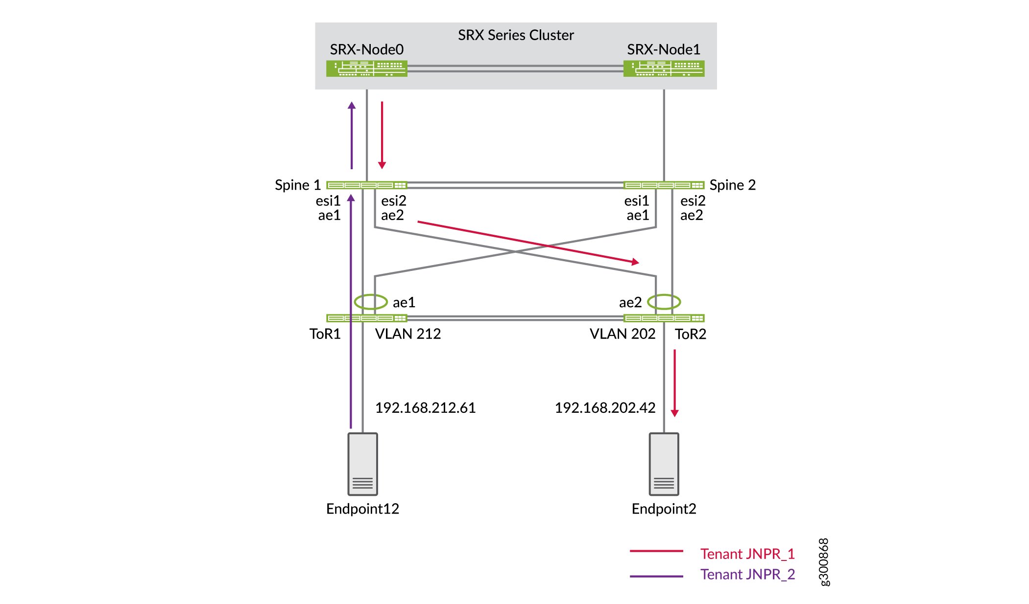
Confirm that the flow table on the SRX Series Firewall shows this traffic traversing the SRX chassis cluster.
user@srx> show security flow session destination-prefix 192.168.202.42
node0:
--------------------------------------------------------------------------

Session ID: 15548, Policy name: Allow_All/7, State: Active, Timeout: 2, Valid
  In: 192.168.212.61/623 --> 192.168.202.42/8204;icmp, Conn Tag: 0x0, If: reth1.992, Pkts: 1, Bytes: 84,
  Out: 192.168.202.42/8204 --> 192.168.212.61/623;icmp, Conn Tag: 0x0, If: reth1.991, Pkts: 1, Bytes: 84,

Session ID: 15551, Policy name: Allow_All/7, State: Active, Timeout: 2, Valid
  In: 192.168.212.61/624 --> 192.168.202.42/8204;icmp, Conn Tag: 0x0, If: reth1.992, Pkts: 1, Bytes: 84,
  Out: 192.168.202.42/8204 --> 192.168.212.61/624;icmp, Conn Tag: 0x0, If: reth1.991, Pkts: 1, Bytes: 84,

Session ID: 15555, Policy name: Allow_All/7, State: Active, Timeout: 4, Valid
  In: 192.168.212.61/625 --> 192.168.202.42/8204;icmp, Conn Tag: 0x0, If: reth1.992, Pkts: 1, Bytes: 84,
  Out: 192.168.202.42/8204 --> 192.168.212.61/625;icmp, Conn Tag: 0x0, If: reth1.991, Pkts: 1, Bytes: 84,
Total sessions: 3
You have configured advanced security for your data center and confirmed that inter-tenant traffic is routed through the SRX chassis cluster.
Configure Data Center Interconnect (DCI)
Requirements
The devices that you configured in How to Configure a Collapsed Spine with EVPN Multihoming and Configure Advanced Security for Inter-Tenant Traffic.
Overview
Now that you have configured a collapsed spine architecture for both data centers and added advanced security to DC1, it is time to connect DC1 and DC2 using Data Center Interconnect (DCI).
Topology
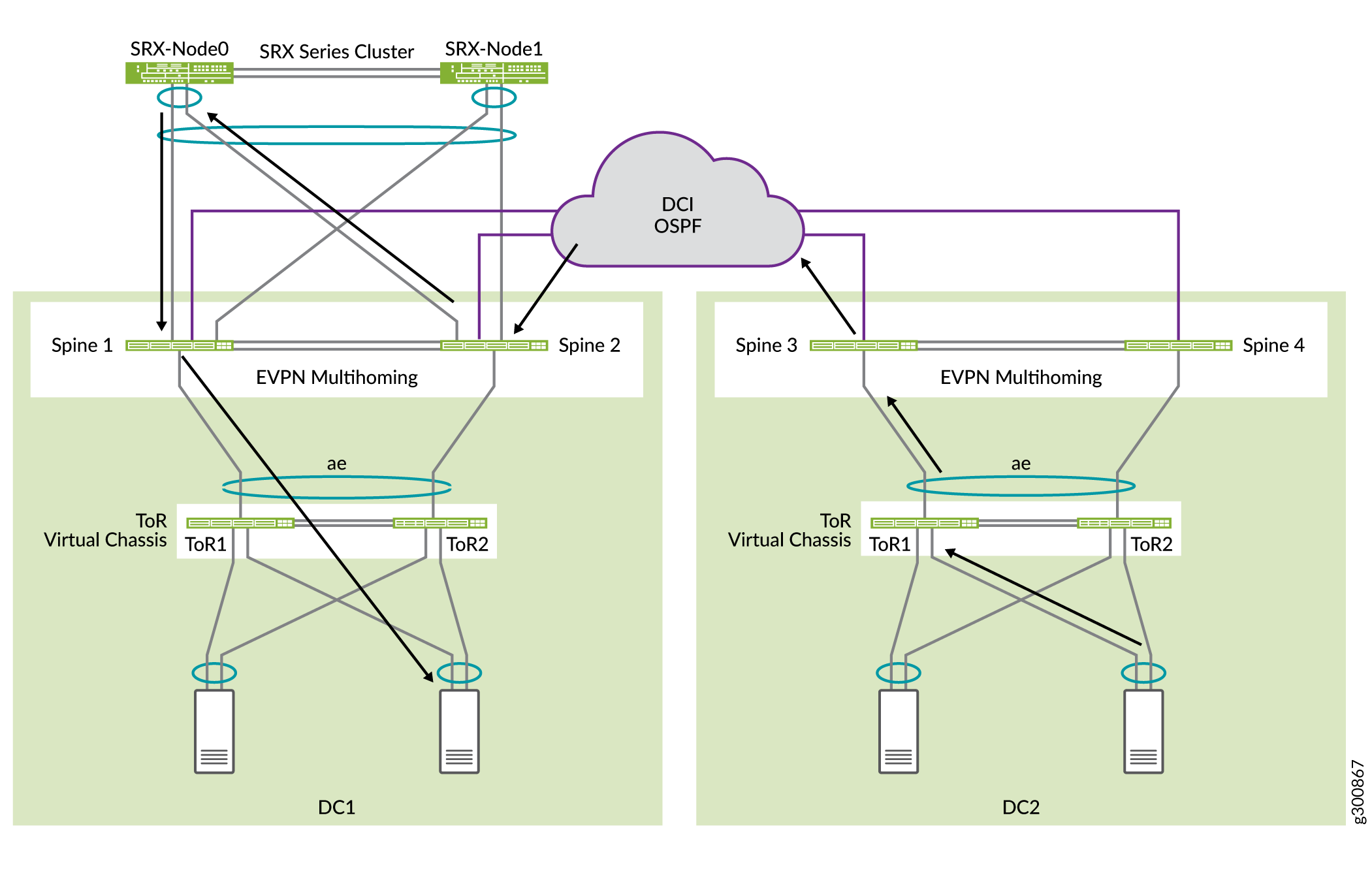
In this example, there is no need to stretch Layer 2 between data centers. Inter-data center communication is routed through the SRX chassis cluster in DC1, as shown in Figure 5. The spine switches each have a WAN routing instance and are connected to the WAN between data centers. The spine switches hand off the Layer 3 routes to the WAN router (not shown in this figure).
The SRX chassic cluster is advertising a 192.168.0.0/16 subnet. The DC2 spine switches Spine 3 and Spine 4 are advertising the two subnets 192.168.221.0/24 and 192.168.222.0/24.
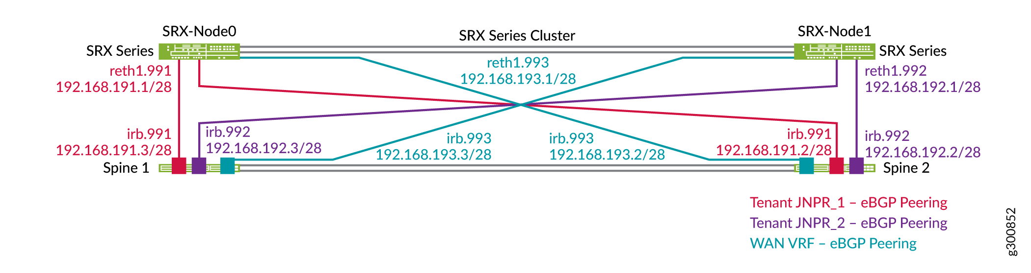
Each SRX Series Firewall is configured with three zones that correspond to the JNPR_1, JNPR_2, and WAN routing instances. All inter-tenant traffic between JNPR_1 and JNPR_2 is routed through the SRX chassis cluster. All traffic between DC1 and DC2 is routed through the SRX chassis cluster using the WAN routing instance. Each SRX Series Firewall has individual EBGP peering with Spine 1 and Spine 2 in each of the routing instances. Figure 6 shows the EBGP peering between the spine switches and the SRX chassis cluster in DC1.
Configuration
Configure the SRX Device
Step-by-Step Procedure
Each SRX Series Firewall must be divided into three zones that correspond to the three routing instances: JNPR_1, JNPR_2, and WAN. You already created the JNPR_1 zone and the JNPR_2 zone in Configure Advanced Security for Inter-Tenant Traffic.
Add a new sub interface on Reth1 for the WAN interconnect.
set interfaces reth1 unit 993 description "DC1 Spine Interconnect for WAN VRF"
set interfaces reth1 unit 993 vlan-id 993
set interfaces reth1 unit 993 family inet address 192.168.193.1/28
Configure the WAN security zone.
set security zones security-zone WAN-Zone host-inbound-traffic system-services ping
set security zones security-zone WAN-Zone host-inbound-traffic protocols bgp
set security zones security-zone WAN-Zone interfaces reth1.993
Configure EBGP for the WAN security zone.
set protocols bgp group INTERCONNECT neighbor 192.168.193.2 peer-as 65312
set protocols bgp group INTERCONNECT neighbor 192.168.193.3 peer-as 65313
Configure the security policies. For simplicity, the security policies in this example are open. In your setup, modify the security policies as necessary.
set security address-book global address 192.168.221.0/24 192.168.221.0/24
set security address-book global address 192.168.222.0/24 192.168.222.0/24
set security policies from-zone WAN-Zone to-zone JNPR_1-Zone policy ALLOW_ALL match source-address 192.168.221.0/24
set security policies from-zone WAN-Zone to-zone JNPR_1-Zone policy ALLOW_ALL match source-address 192.168.222.0/24
set security policies from-zone WAN-Zone to-zone JNPR_1-Zone policy ALLOW_ALL match destination-address any
set security policies from-zone WAN-Zone to-zone JNPR_1-Zone policy ALLOW_ALL match application any
set security policies from-zone WAN-Zone to-zone JNPR_1-Zone policy ALLOW_ALL then permit
set security policies from-zone WAN-Zone to-zone JNPR_2-Zone policy ALLOW_ALL match source-address 192.168.221.0/24
set security policies from-zone WAN-Zone to-zone JNPR_2-Zone policy ALLOW_ALL match source-address 192.168.222.0/24
set security policies from-zone WAN-Zone to-zone JNPR_2-Zone policy ALLOW_ALL match destination-address any
set security policies from-zone WAN-Zone to-zone JNPR_2-Zone policy ALLOW_ALL match application any
set security policies from-zone WAN-Zone to-zone JNPR_2-Zone policy ALLOW_ALL then permit
set security policies from-zone JNPR_1-Zone to-zone WAN-Zone policy ALLOW_ALL match source-address any
set security policies from-zone JNPR_1-Zone to-zone WAN-Zone policy ALLOW_ALL match destination-address 192.168.222.0/24
set security policies from-zone JNPR_1-Zone to-zone WAN-Zone policy ALLOW_ALL match destination-address 192.168.221.0/24
set security policies from-zone JNPR_1-Zone to-zone WAN-Zone policy ALLOW_ALL match application any
set security policies from-zone JNPR_1-Zone to-zone WAN-Zone policy ALLOW_ALL then permit
set security policies from-zone JNPR_2-Zone to-zone WAN-Zone policy ALLOW_ALL match source-address any
set security policies from-zone JNPR_2-Zone to-zone WAN-Zone policy ALLOW_ALL match destination-address 192.168.222.0/24
set security policies from-zone JNPR_2-Zone to-zone WAN-Zone policy ALLOW_ALL match destination-address 192.168.221.0/24
set security policies from-zone JNPR_2-Zone to-zone WAN-Zone policy ALLOW_ALL match application any
set security policies from-zone JNPR_2-Zone to-zone WAN-Zone policy ALLOW_ALL then permit
Configure Spine Switches
Step-by-Step Procedure
-
Configure the routing instances and irb interface on Spine 1.
set interfaces irb unit 993 family inet address 192.168.193.3/28
set routing-instances WAN_VRF description "VRF for tenant WAN"
set routing-instances WAN_VRF instance-type vrf
set routing-instances WAN_VRF interface et-0/0/48.0
set routing-instances WAN_VRF interface irb.993
set routing-instances WAN_VRF interface lo0.103
set routing-instances WAN_VRF route-distinguisher 192.168.253.13:103
set routing-instances WAN_VRF vrf-target target:3:65001
set routing-instances WAN_VRF vrf-table-label
set routing-instances WAN_VRF routing-options auto-export
set routing-instances WAN_VRF routing-options multipath
set routing-instances WAN_VRF protocols bgp group INTERCONNECT type external
set routing-instances WAN_VRF protocols bgp group INTERCONNECT import Interconnect_WAN-IMPORT
set routing-instances WAN_VRF protocols bgp group INTERCONNECT family inet unicast
set routing-instances WAN_VRF protocols bgp group INTERCONNECT authentication-key "$ABC123"
set routing-instances WAN_VRF protocols bgp group INTERCONNECT export Interconnect_WAN-EXPORT
set routing-instances WAN_VRF protocols bgp group INTERCONNECT local-as 65313
set routing-instances WAN_VRF protocols bgp group INTERCONNECT multipath multiple-as
set routing-instances WAN_VRF protocols bgp group INTERCONNECT bfd-liveness-detection minimum-interval 1000
set routing-instances WAN_VRF protocols bgp group INTERCONNECT bfd-liveness-detection multiplier 3
set routing-instances WAN_VRF protocols bgp group INTERCONNECT neighbor 192.168.193.1 peer-as 65200

set routing-instances WAN_VRF protocols bgp group WAN_UNDERLAY type external
set routing-instances WAN_VRF protocols bgp group WAN_UNDERLAY description "Connection to EBGP WAN_UNDERLAY"
set routing-instances WAN_VRF protocols bgp group WAN_UNDERLAY family inet unicast
set routing-instances WAN_VRF protocols bgp group WAN_UNDERLAY authentication-key "$ABC123"
set routing-instances WAN_VRF protocols bgp group WAN_UNDERLAY local-as 65313
set routing-instances WAN_VRF protocols bgp group WAN_UNDERLAY multipath multiple-as
set routing-instances WAN_VRF protocols bgp group WAN_UNDERLAY bfd-liveness-detection minimum-interval 350
set routing-instances WAN_VRF protocols bgp group WAN_UNDERLAY bfd-liveness-detection multiplier 3
set routing-instances WAN_VRF protocols bgp group WAN_UNDERLAY neighbor 192.168.100.2 peer-as 65300
Configure the routing instances on Spine 2.
set interfaces irb unit 993 family inet address 192.168.193.2/28
set routing-instances WAN_VRF description "VRF for tenant WAN"
set routing-instances WAN_VRF instance-type vrf
set routing-instances WAN_VRF interface et-0/0/48.0
set routing-instances WAN_VRF interface irb.993
set routing-instances WAN_VRF interface lo0.103
set routing-instances WAN_VRF route-distinguisher 192.168.253.12:103
set routing-instances WAN_VRF vrf-target target:3:65001
set routing-instances WAN_VRF vrf-table-label
set routing-instances WAN_VRF routing-options auto-export
set routing-instances WAN_VRF routing-options multipath
set routing-instances WAN_VRF protocols bgp group INTERCONNECT type external
set routing-instances WAN_VRF protocols bgp group INTERCONNECT import Interconnect_WAN-IMPORT
set routing-instances WAN_VRF protocols bgp group INTERCONNECT family inet unicast
set routing-instances WAN_VRF protocols bgp group INTERCONNECT authentication-key "$ABC123"
set routing-instances WAN_VRF protocols bgp group INTERCONNECT export Interconnect_WAN-EXPORT
set routing-instances WAN_VRF protocols bgp group INTERCONNECT local-as 65312
set routing-instances WAN_VRF protocols bgp group INTERCONNECT multipath multiple-as
set routing-instances WAN_VRF protocols bgp group INTERCONNECT bfd-liveness-detection minimum-interval 1000
set routing-instances WAN_VRF protocols bgp group INTERCONNECT bfd-liveness-detection multiplier 3
set routing-instances WAN_VRF protocols bgp group INTERCONNECT neighbor 192.168.193.1 peer-as 65200

set routing-instances WAN_VRF protocols bgp group WAN_UNDERLAY type external
set routing-instances WAN_VRF protocols bgp group WAN_UNDERLAY description "Connection to EBGP WAN_UNDERLAY"
set routing-instances WAN_VRF protocols bgp group WAN_UNDERLAY family inet unicast
set routing-instances WAN_VRF protocols bgp group WAN_UNDERLAY authentication-key "$ABC123"
set routing-instances WAN_VRF protocols bgp group WAN_UNDERLAY local-as 65312
set routing-instances WAN_VRF protocols bgp group WAN_UNDERLAY multipath multiple-as
set routing-instances WAN_VRF protocols bgp group WAN_UNDERLAY bfd-liveness-detection minimum-interval 350
set routing-instances WAN_VRF protocols bgp group WAN_UNDERLAY bfd-liveness-detection multiplier 3
set routing-instances WAN_VRF protocols bgp group WAN_UNDERLAY neighbor 192.168.100.0 peer-as 65300
Configure EBGP on Spine 3.
set protocols bgp group WAN_UNDERLAY type external
set protocols bgp group WAN_UNDERLAY description "Connection to EBGP WAN_UNDERLAY"
set protocols bgp group WAN_UNDERLAY family inet unicast
set protocols bgp group WAN_UNDERLAY authentication-key "$ABC123"
set protocols bgp group WAN_UNDERLAY export WAN_EXPORT
set protocols bgp group WAN_UNDERLAY local-as 65322
set protocols bgp group WAN_UNDERLAY multipath multiple-as
set protocols bgp group WAN_UNDERLAY bfd-liveness-detection minimum-interval 350
set protocols bgp group WAN_UNDERLAY bfd-liveness-detection multiplier 3
set protocols bgp group WAN_UNDERLAY neighbor 192.168.100.10 peer-as 65300

set policy-options policy-statement WAN_EXPORT term DIRECT_ROUTES from protocol direct
set policy-options policy-statement WAN_EXPORT term DIRECT_ROUTES from route-filter 192.168.221.0/24 exact
set policy-options policy-statement WAN_EXPORT term DIRECT_ROUTES from route-filter 192.168.222.0/24 exact
set policy-options policy-statement WAN_EXPORT term DIRECT_ROUTES then accept
Configure EBGP on Spine 4.
set protocols bgp group WAN_UNDERLAY type external
set protocols bgp group WAN_UNDERLAY description "Connection to EBGP WAN_UNDERLAY"
set protocols bgp group WAN_UNDERLAY family inet unicast
set protocols bgp group WAN_UNDERLAY authentication-key "$ABC123"
set protocols bgp group WAN_UNDERLAY export WAN_EXPORT
set protocols bgp group WAN_UNDERLAY local-as 65323
set protocols bgp group WAN_UNDERLAY multipath multiple-as
set protocols bgp group WAN_UNDERLAY bfd-liveness-detection minimum-interval 350
set protocols bgp group WAN_UNDERLAY bfd-liveness-detection multiplier 3
set protocols bgp group WAN_UNDERLAY neighbor 192.168.100.16 peer-as 65300

set policy-options policy-statement WAN_EXPORT term DIRECT_ROUTES from protocol direct
set policy-options policy-statement WAN_EXPORT term DIRECT_ROUTES from route-filter 192.168.221.0/24 exact
set policy-options policy-statement WAN_EXPORT term DIRECT_ROUTES from route-filter 192.168.222.0/24 exact
set policy-options policy-statement WAN_EXPORT term DIRECT_ROUTES then accept
Verify DCI Routes
Step-by-Step Procedure
Verify the routes on the SRX chassis cluster. The SRX should learn all the specific routes for the different subnets.
user@srx> show route
inet.0: 31 destinations, 37 routes (31 active, 0 holddown, 0 hidden)
+ = Active Route, - = Last Active, * = Both

192.168.201.0/24   *[BGP/170] 00:59:11, localpref 100
                  	AS path: 65113 I, validation-state: unverified
                	> to 192.168.191.3 via reth1.991
192.168.201.10/32  *[BGP/170] 00:00:07, localpref 100
                  	AS path: 65113 I, validation-state: unverified
                	> to 192.168.191.3 via reth1.991
192.168.201.81/32  *[BGP/170] 00:00:07, localpref 100
                  	AS path: 65113 I, validation-state: unverified
                	> to 192.168.191.3 via reth1.991
192.168.202.0/24   *[BGP/170] 00:59:11, localpref 100
                  	AS path: 65113 I, validation-state: unverified
                	> to 192.168.191.3 via reth1.991
192.168.202.61/32  *[BGP/170] 00:59:11, localpref 100
                  	AS path: 65113 I, validation-state: unverified
                	> to 192.168.191.3 via reth1.991
192.168.202.62/32  *[BGP/170] 00:59:11, localpref 100
                  	AS path: 65113 I, validation-state: unverified
                	> to 192.168.191.3 via reth1.991
192.168.203.0/24   *[BGP/170] 00:59:11, localpref 100
                  	AS path: 65113 I, validation-state: unverified
                	> to 192.168.191.3 via reth1.991
192.168.203.61/32  *[BGP/170] 00:15:09, localpref 100
                  	AS path: 65113 I, validation-state: unverified
                	> to 192.168.191.3 via reth1.991
192.168.211.0/24   *[BGP/170] 00:34:09, localpref 100
                  	AS path: 65213 I, validation-state: unverified
                	> to 192.168.192.3 via reth1.992
192.168.212.0/24   *[BGP/170] 00:34:09, localpref 100
                  	AS path: 65213 I, validation-state: unverified
                	> to 192.168.192.3 via reth1.992
192.168.221.0/24   *[BGP/170] 00:25:07, localpref 100
                  	AS path: 65313 65300 65322 I, validation-state: unverified
                	> to 192.168.193.3 via reth1.993
192.168.222.0/24   *[BGP/170] 00:25:07, localpref 100
                  	AS path: 65313 65300 65322 I, validation-state: unverified
                	> to 192.168.193.3 via reth1.993
Verify the routes on Spine 1 and Spine 2. The SRX cluster advertises the 192.168.0.0/16 summary route to the spine devices on all the VRFs. All inter-VRF traffic and DCI traffic goes through the SRX chassis cluster.
user@spine1> show route 192.168.0.0
JNPR_1_VRF.inet.0: 19 destinations, 23 routes (19 active, 0 holddown, 0 hidden)
+ = Active Route, - = Last Active, * = Both

192.168.0.0/16 	*[BGP/170] 01:05:15, localpref 100
                  	AS path: 65200 I, validation-state: unverified
                	>  to 192.168.191.1 via irb.991

JNPR_2_VRF.inet.0: 13 destinations, 16 routes (13 active, 0 holddown, 0 hidden)
+ = Active Route, - = Last Active, * = Both

192.168.0.0/16 	*[BGP/170] 00:40:12, localpref 100
                  	AS path: 65200 I, validation-state: unverified
                	>  to 192.168.192.1 via irb.992

WAN_VRF.inet.0: 12 destinations, 12 routes (12 active, 0 holddown, 0 hidden)
+ = Active Route, - = Last Active, * = Both

192.168.0.0/16 	*[BGP/170] 01:04:59, localpref 100
                  	AS path: 65200 I, validation-state: unverified
                	>  to 192.168.193.1 via irb.993
Verify the routes on Spine 3 and Spine 4. The DC2 spine devices receive the aggregate route from the WAN VRFs on the DC1 spine devices. All traffic between the two data centers is routed through the SRX chassis cluster.
user@spine3> show route 192.168.0.0
inet.0: 24 destinations, 26 routes (21 active, 0 holddown, 0 hidden)
+ = Active Route, - = Last Active, * = Both

192.168.0.0/16  	[BGP ] 00:11:47
                  	AS path: 65300 65313 65200 I, validation-state: unverified
                	>  to 192.168.100.10 via et-0/0/30.0
You have connected your collapsed spine data center networks with DCI.