Part 2: Configure and Manage the EX Switch and the Mist AP in the Juniper Mist Cloud
Day 0: Claim or Adopt an EX Switch into the Juniper Mist Cloud
- Overview
- How to Claim a Cloud-Ready Switch
- How to Adopt a Previously Deployed Switch
- Troubleshooting
Overview
In this section you adopt or claim your EX switch and Mist AP into the Juniper Mist Cloud.
With Juniper Mist Cloud services, you can use Juniper Mist Wired Assurance to centrally manage all your Juniper switches. Juniper Mist Wired Assurance gives you full visibility on the devices that comprise your network’s access layer. The Juniper Mist portal provides a user interface to access your architecture through the AI-driven cloud services with your Juniper Mist account. You can monitor, measure, and get alerts on key compliance metrics on the wired network including switch version and PoE compliance, switch-AP affinity, and VLAN insights.
Juniper switches and Juniper access points (APs) combine to support dense, heavily utilized networks that scale to support a large number of mobile devices, while providing end-user security and reliable performance.
We group the adoption and management of EX Series Switches into three categories:
Day 0 represents zero-touch switch provisioning with single-click activation to claim new switches, or to adopt existing switches into the Juniper Mist Cloud.
Tip:You claim Cloud-ready switches in the Juniper Mist Cloud. In contrast, you adopt previously deployed (brownfield) switches.
Day 1 represents template-based configuration for managing switch configurations across the organization, multiple sites, or individual switches.
Day 2 represents ongoing switch insights and intelligence, leveraging the Marvis Virtual Network Assistant driven by Mist AI.
How to Claim a Cloud-Ready Switch
You need an activation code to claim a cloud-ready switch. A cloud-ready switch is also referred to as a “Greenfield Switch”, which denotes a switch that is deployed for the first time. Juniper e-mails activation codes to the address on record at the time of purchase. You can also contact the Juniper Mist Customer Engagement team to get your activation code. Use the activation code to adopt any switches and access points that are part of the purchase order. You also use this code to claim any subscriptions included in your purchase.
A cloud-ready switch comes with a claim code and a cloud ready sticker on the packaging box. These switches also have a QR code on the front or back of the switch chassis, depending on the model type.

Claim a Cloud-Ready Switch
Step-by-step Procedure
This procedure describes how to claim a cloud-ready switch in the Juniper Mist Cloud.
-
Use a Web browser to log in to your Juniper Mist account. The Monitor page appears, showing an overview of the Juniper Mist Cloud and any connected Juniper access points and clients. Click on Organization > Inventory in the menu on the left to open the Juniper Mist Inventory Screen.

-
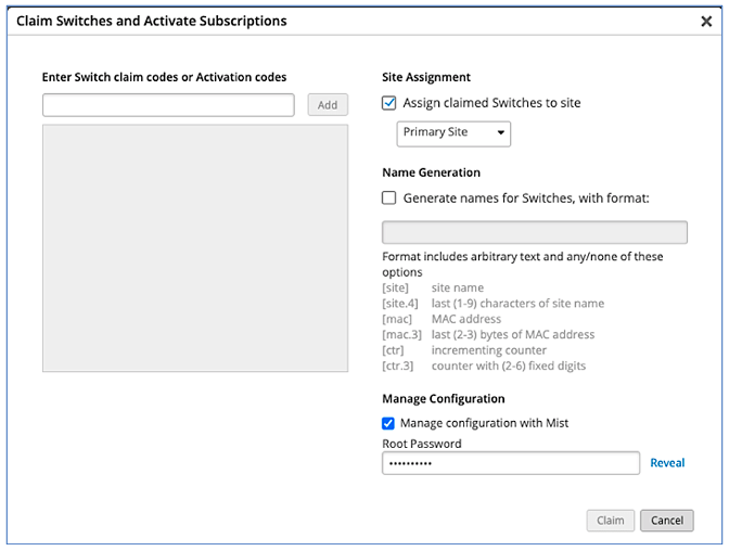
Select Switches at the top of the Inventory screen. Click the Claim Switches button and enter the activation or the claim code for the switch.
-
Complete the fields on the screen. Select the Manage configuration with Mist check box and enter a root password for the switch. Note that this choice puts the switch under the management of the Juniper Mist portal. As such, we recommend that local configuration using the CLI be restricted to prevent conflicts. For example, you might want to create a system login message on the switch to warn against making configuration changes locally, from the CLI.
-
Remove the switch from the box and provide the switch management port with Internet access. Next, power the switch on. As part of the zero touch provisioning (ZTP) process, the switch automatically accesses the phone home server (PHS) and connects to the Juniper Mist Cloud for configuration updates.
Once the ZTP process resolves, the switch automatically appears in the Inventory page. If the switch does not appear after a few minutes, despite refreshing the web page, try logging out and then logging back in. If you still do not see the switch, see Troubleshooting for information about how to confirm whether the device is connected to the cloud.
How to Adopt a Previously Deployed Switch
Here, the term “previously deployed” switch refers to older EX switches that do not ship with a cloud-ready activation code. Non cloud-ready switches called “brownfield” switches in this context.
We recommend that you back up the existing configuration on the switch before getting started if the switch is used as part of an existing deployment.
At this time the Juniper Mist Cloud does not support the import of a pre-existing brownfield switch configuration. Once adopted into the Mist Cloud you must reconfigure the switch through the cloud for the desired functionality.
To prevent users from using the CLI to configure the switch after adoption into the Juniper Mist Cloud, you might also want to create a system login message on the switch to warn against making configuration changes, or you can restrict their management access altogether by changing the password or by placing restrictions on the CLI user accounts.
Adopt a Brownfield Switch to the Juniper Mist Cloud
Step-by-step Procedure
This procedure describes how to set up a secure connection between a supported EX Series switch running a supported version of Junos OS. Also, be sure you can log in to the Juniper Mist portal.
You loaded a factory default configuration (or zeroized) the EX switch in a previous step. You also verified the switch has internet connectivity through the SRX device.
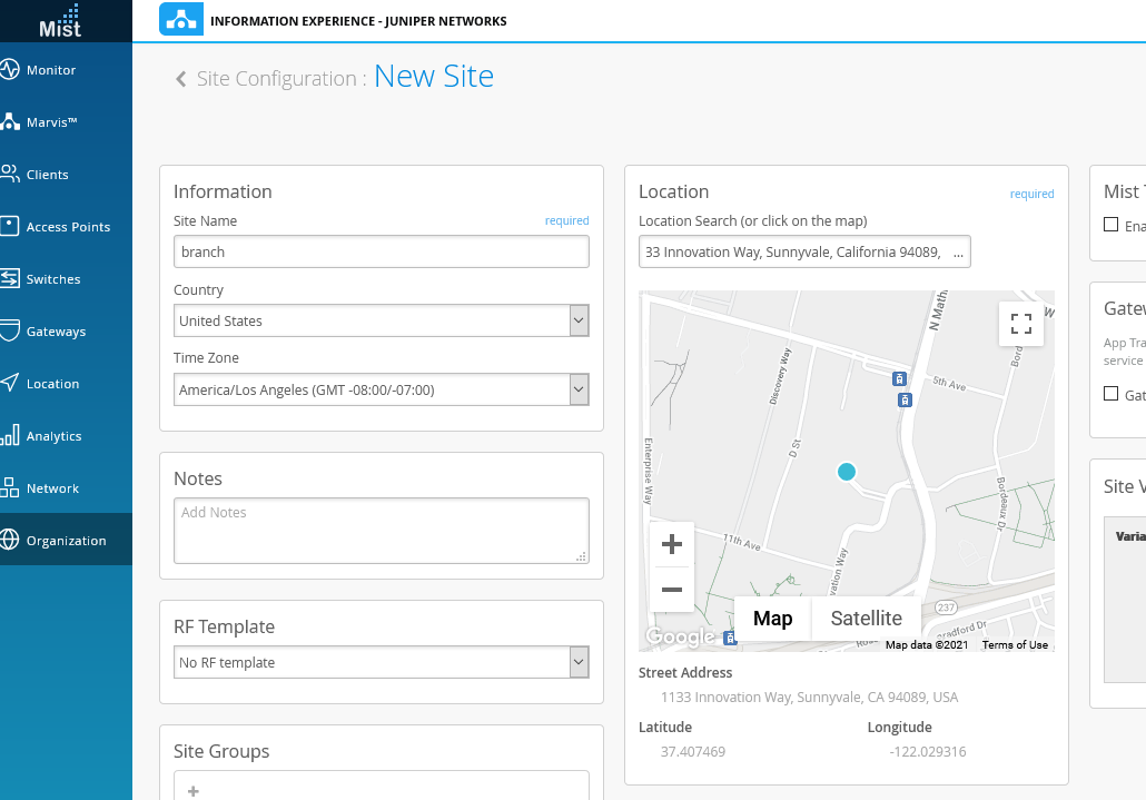
Create a branch site in Juniper Mist Cloud. Log in to your organization on Juniper Mist Cloud Click Organization > Site Configuration to open the Sites screen. Click on Create Site and assign the name branch to the new site. You must also enter a location for the site. In this case we enter the address for Juniper’s headquarters.
Scroll down to the section on switch management and add the desired root password. Later, when you enable configuration management, the Juniper Mist Cloud updates the switch configuration with the password specified. Click on Save to create the new branch location, as shown.
-
Adopt the brownfield switch. Click Organization > Inventory to open the Inventory screen. In this example both the Access Points and Switches tabs are empty. Depending on your organization’s login you might see devices that have already be claimed/adopted.

-
Select Switches at the top of the Inventory screen and click Adopt Switches in the upper-right corner to generate the Junos OS CLI commands needed to establish secure communications with the Juniper Mist Cloud.
-
The commands configure the switch with a Juniper Mist user account and enable SSH connectivity to the Juniper Mist Cloud. This SSH connectivity uses TCP over port 2200. This port is used for configuration updates and sending telemetry data to the cloud. If you later experience problems connecting to the Juniper Mist Cloud, check to ensure that your organization allows outbound connection requests and the matching return traffic for TCP port 2200 sent to and from the Juniper Mist service.
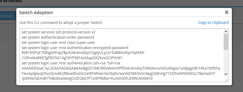
In the window that appears, click Copy to Clipboard to get the commands from the Juniper Mist Cloud.
On the console of the switch, type
.configurationto enter configuration mode and then paste the commands you just copied. Use thetopcommand if you are not already at the base level of the configuration hierarchy. Be sure to commit the changes-
While on the Juniper Mist portal, refresh your browser to update the screen. Within a few minutes the newly adopted switch appears in the inventory list.

-
Select the switch you just added and click the More drop-down list at the top right side of the screen, and then click Assign to Site to open the Assign Switches window. Select the branch site you created earlier, but do not click the Manage Configuration option yet. You enable configuration management later, after you have built the configuration template.

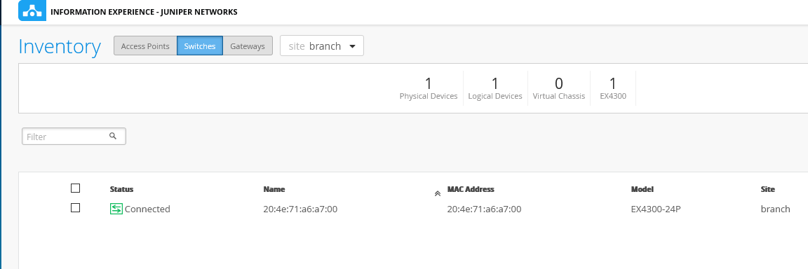
Click Assign to Site when done. The display confirms the switch belongs to the branch site. After dismissing the confirmation window the newly adopted switch appears in the inventory with a green status. You might need to refresh the page to see the expected switch status.
Troubleshooting
Confirm your connection from the switch to the Juniper Mist Cloud by running the Junos OS command below on your switch console.
user@host> show system connections | grep 2200
tcp4       0      0  192.168.1.3.54897         13.56.90.212.2200             ESTABLISHED
The command output shows the switch has successfully established a TCP connection to the Juniper Mist Cloud. It includes the IP address of the switch interface that is used to initiate the connection, the destination IP address of the Juniper Mist Cloud (which can vary due to load balancing), and the connection status. The 192.168.1.3 address is assigned by the SRX device to the ge-0/0/1 port on the EX switch via DHCP.
If you do not see the switch in the Inventory list, an external firewall might be blocking either the outgoing connection request or the returning acknowledgment messages. When communications are successful, the switch appears in Organization > Inventory > Switches.
In this example, console access is used for the EX switch. All Internet access provided by the SRX Services Gateway. If your switch has an Ethernet management link, it might obtain an IP address and default route over the management network once you activate the factory default configuration. This situation can result in two default routes, one pointing to the management network and one to the SRX. In this scenario you should confirm that both paths are open to TCP port 2200 in both the outgoing and incoming directions.
Day 1: Template-based EX Switch Configuration with Device and Port Profiles
Overview
A key feature of switch management through the Juniper Mist Cloud is the ability to use configuration templates and a hierarchical model to group switches to make bulk updates. Templates allow you to have consistent configurations across the organization, and to conveniently apply configuration with granularity to a particular switch, to a site, or at scale across your entire network.
You create a template configuration and then apply those settings to all the devices in a group. When a conflict occurs, the more narrow settings override the broader settings. For example, when settings at both the branch and organizational levels apply to the same device, the more narrow settings (in this case, branch) override the broader settings defined at the organization level.
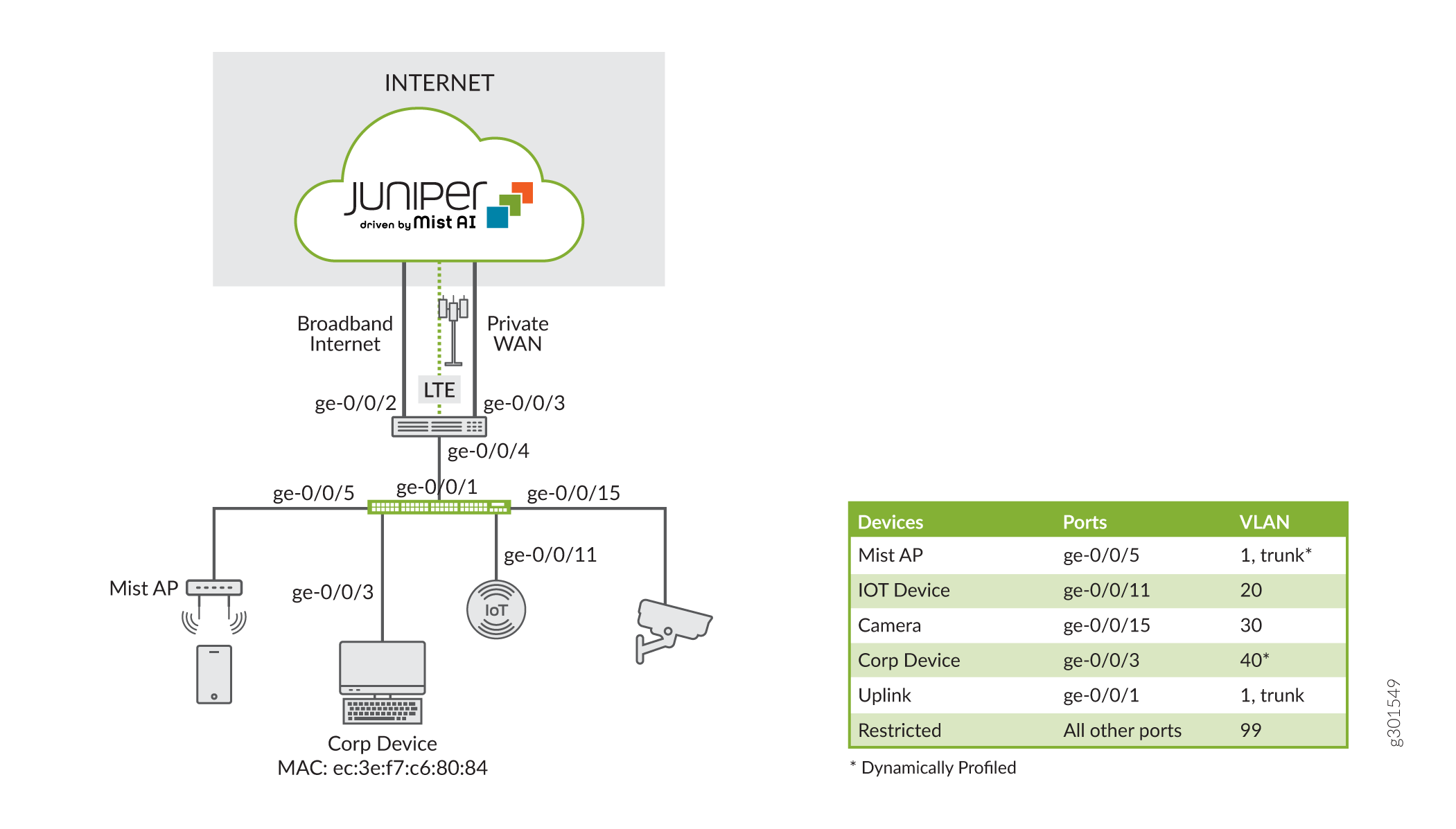
Figure 2 summarizes the example topology and highlights the VLANs/networks behind the SRX device.
Procedure
Follow this procedure to configure the EX switch for this configuration example using the Juniper Mist Cloud.
Step-by-step Procedure
-
A switch configuration template lets you define the standard configurations that are used for all the switches in the branch. The template also allows you to apply specific configurations to select switches when desired. Begin by creating a Switch Configuration template by clicking on Organization > Switch Template in the menu on the left. Use the Create Template button to create a template called branch_template.
In this example, you populate the template as shown below:
Click on the headings (All Switches Configuration, Shared Elements, and Select Switches Configuration) to expand a section, and the down arrow to collapse the section when done.
-
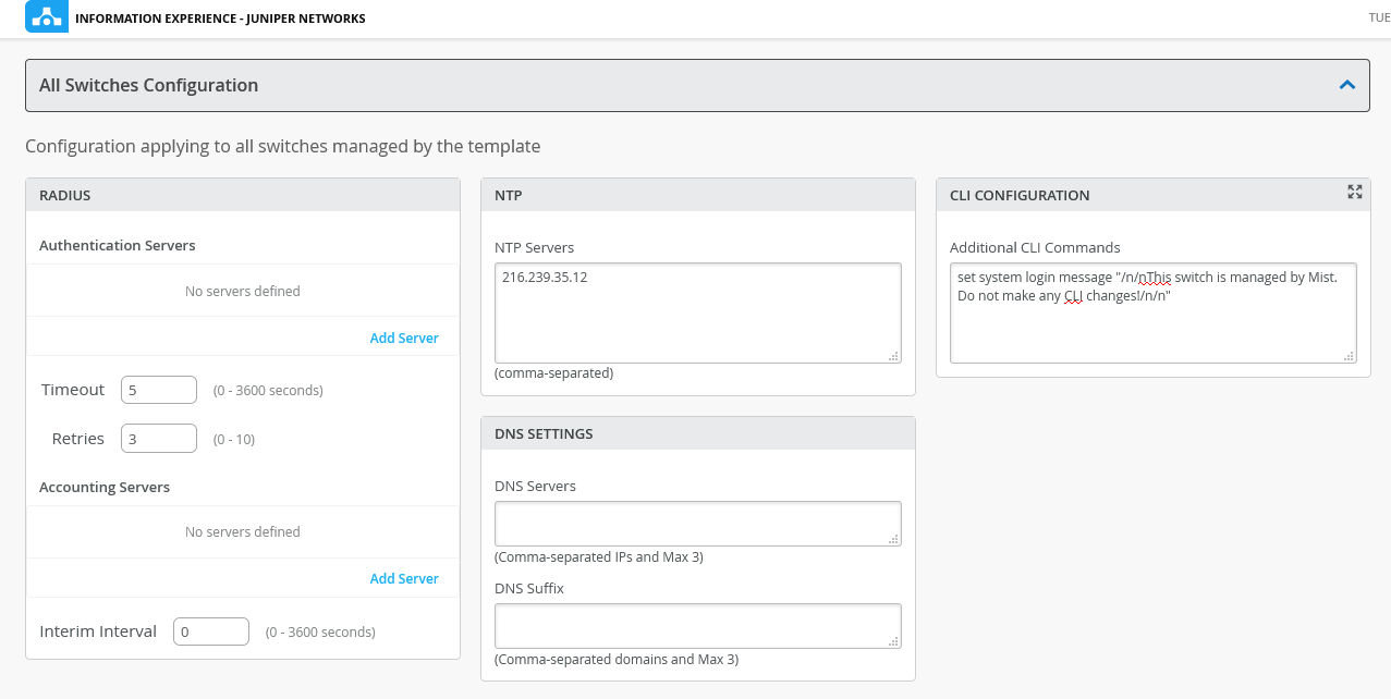
Under the All Switches Configuration, we will add the following parameters:
-
Configure an NTP server for the branch. You use the same public NTP address configured in the SRX.
-
Add a custom login banner to warn users the switch is under control of the Juniper Mist Cloud.
 Tip:
Tip:A configuration template supports both authorization and accounting services. These fields are left blank as nether is used in this example. The DNS fields are left blank. In this example the SRX assigns both a domain name and a DNS server to the EX switch and the Mist AP via DHCP.
-
-
Scroll down to Shared Elements to add the following:
-
Under NETWORKS define the branch office’s networks and the associated VLANs according to Table 1. In this example we use the system defined “default” network for the native VLAN on trunk interfaces.
Table 1: Network to VLAN Mapping Network Name
VLAN ID
iot_network
20
camera_network
30
corp_network
40
restricted
99
-
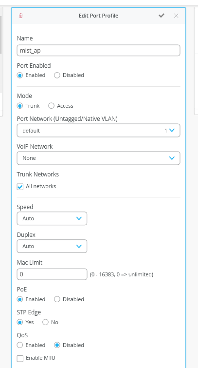
Under PORT PROFILES, create new port profiles with the names ”mist_ap”, “iot_device", “camera_device”, “corp_device”, and “restricted_device”, and map the port profiles to the above networks (VLANs). Use Table 2 to set port parameters such as trunk vs. access, STP, and POE. We enable STP on edge/access ports in this example as a best practice to guard against loops.
Table 2: Port Profile Settings Port Profile
Port Settings
mist_ap
Trunk (all), default (VLAN 1), POE, STP edge
iot_device
Access, VLAN 20, STP edge
camera_device
Access, VLAN 30, STP edge
corp_device
Access, VLAN 40, STP edge
restricted_device
Access, VLAN 99, POE, STP Edge
Note:Be sure to set the correct mode of operation (trunk vs. access) and POE for the port groups. The Mist AP in this example requires that POE be enabled. In addition, dynamic profiling is used for the Mist AP. This means the port attached to the Mist AP is initially placed in the restricted VLAN. The port is reassigned to the “mist_ap” profile once the device is recognized as a Mist AP. Therefore, you must enable POE for the “restricted_device” profile to ensure the Mist AP remains powered up and able to identify itself using LLDP.
The settings for the “mist_ap” port group are shown:
-
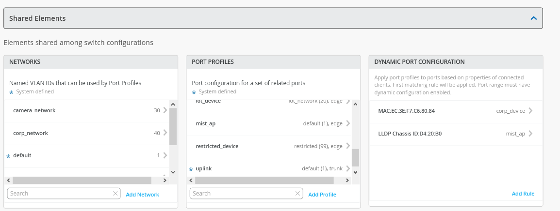
This example demonstrates a mix of static and dynamic port profiles. Dynamic profiling allows a device to be placed into a specific VLAN based on user authentication or identification of the device. In this step you define two dynamic port configuration profiles.
Under Dynamic Port Configuration, create a rule that assigns the port profile “mist_ap” to Juniper access points automatically. The rule uses LLDP to detect the chassis ID. When it identifies a device with the first three octets of the chassis ID matching our Juniper access point, it assigns the device to the “mist_ap” profile you created earlier. In this example we match on the value “D4:20:B0”.
Tip:Verify the MAC address of your Mist AP using the sticker on the chassis, or with a
show
                                                  lldp neighbors
command on the EX.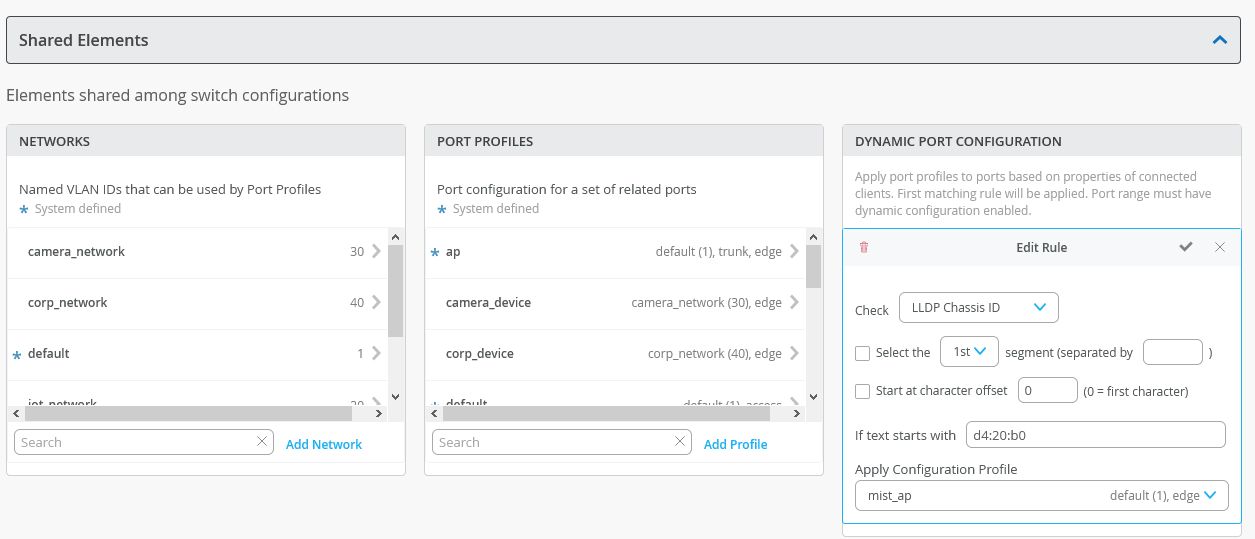
-
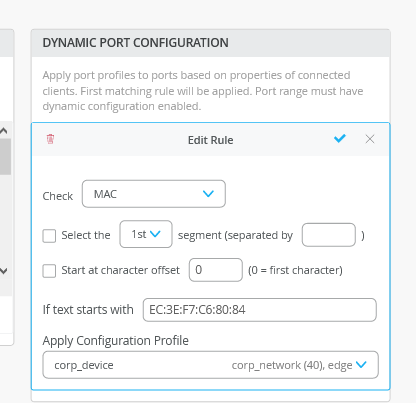
Under Dynamic Port Configuration, create a second rule that dynamically assigns the device with MAC address “ec:3e:f7:c6:80:84” to the “corp_network” profile. This MAC address is assigned to the wired client that is attached to the ge-0/0/3 interface of the EX switch.
The completed Shared Elements screen is shown:
-
-
Under Select Switches Configurations, we will add the following:
-
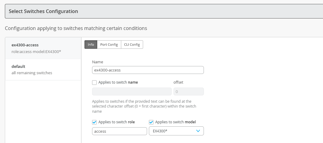
Under Info create a rule to associate a port profile with your switch. For this example you add a rule that maps the EX4300 switch to an "access" role.
-
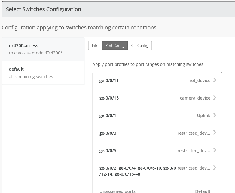
Click the Port Config tab and map the port profiles defined under Shared Elements to physical switch ports based on table Table 3. To better demonstrate dynamic port profiling, both the Mist AP and the corporate device are placed into a restricted VLAN with dynamic profiling enabled. The other devices are statically mapped to their associated networks.
Table 3: EX Switch Port Profiles Interface
Function
Profile-* indicates a system defined profile
ge-0/0/1
Trunk Uplink to SRX
*Uplink
ge-0/0/3
Roaming Corporate Device
restricted_device, dynamic profiling
ge-0/0/5
Trunk Uplink from Mist AP
restricted_device, dynamic profiling
ge-0/0/11
Wired IoT
iot_device
ge-0/0/15
Wired Camera
camera_device
All other ports
Restricted VLAN
restricted_device
Note:Ports that are not assigned a port profile inherit the system default profile. The default profile places these ports into VLAN 1, which allows attached devices to obtain a DHCP address from the SRX on the 192.168.1.0/24 network. In this example you define a port range that places all unused ports into the restricted VLAN with dynamic profiling disabled. This setting effectively places these unused ports into a quarantine network that cannot pass through the SRX. Recall that VLAN 99 is not configured on the SRX end of the trunk interface, and that no DHCP pool has been configured for this VLAN.
Recall that dynamic profiling is enabled for the Mist AP on ge-0/0/5 and the corporate device on ge-0/0/3. Be sure to select the Enable Dynamic Configuration option when you map these ports to the "restricted_device" profile as shown.
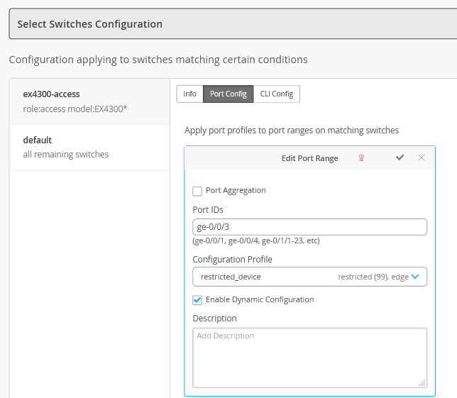
The completed port configuration is shown:
-
You can include configuration statements in the CLI Config tab when the configuration is not supported on the Juniper Mist Cloud. In this example, we have set a custom login banner that applies to all switches in the branch location using the All Switches Configuration portion of the template. This example does not require switch specific CLI configuration.
Note:When done mapping switch ports, be sure to click the check mark to save the port profile, and then click the Save button at the top of the page to save the changes to the branch template.
-
To map the switch template that you created to your branch site, click Network > Switch Configuration in the menu on the left. Select the check box next to your branch site and click the Assign to Template link to map the “branch” template to your site.

-
Assign your EX switch to the branch site. Click Switches in the menu on the left, then select the branch site in the site pull down menu. Next, select your switch and use the More pull down menu to select Assign to Site and add the switch to the branch site. Recall the EX switch current has a factory default modified with a root password. Also note this switch has not been under management by the Juniper Mist Cloud. Therefore, you select the Do not retain configuration option.
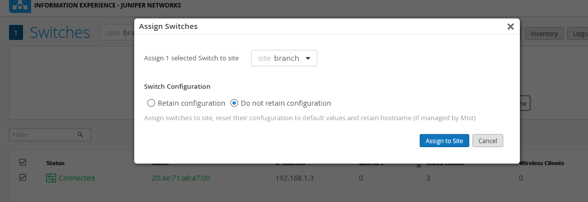
Next, click the Assign to Site button. The Assign Switches confirmation dialog box confirms the site assignment. Dismiss the window by clicking the Close button.

-
In this step you activate Juniper Mist Cloud configuration management for the EX switch. This causes the configuration settings in the “branch_template” to be activated in the switch.
Warning:Once under the control of the Juniper Mist Cloud you should not make any CLI changes directly. Manual CLI changes might conflict with the Mist managed configuration. In addition, manual changes might be overwritten when the cloud pushes an updated configuration.
While still on the Switches page and viewing the branch site, select your switch to view its details. Scroll down to the Switch Configuration section. At this time the switch is not .
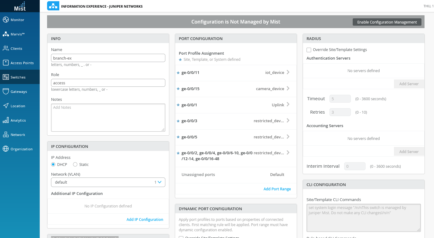
Before enabling configuration management, make the following changes to the switch configuration:
-
Assign the host name for your switch. In this example we use “branch-ex”
-
Assign a role of “access” to activate the select switches portion of your branch template. In the branch template you specified that the switch-specific port configuration is applied to any switch of type “EX4300*” with a role of “access”. Once you specify a role of “access”, the Port Configuration portion of the window should populate with the port settings from the branch template.
-
The rest of the settings are left at their defaults. When needed you can override many of the template settings. Alternatively, you can use the Additional CLI Commands box to include specific CLI commands for the selected switch. The CLI commands are merged with the template configuration before being sent to the switch.
Note:This example uses console access. If you plan to use an Ethernet based management network you can use the IP Configuration (Out of Band) section to specify the use of DHCP or a statically assigned management address. Make sure that the switch does not receive a default route when using DHCP based management. In this example default routes are used to direct traffic from the branch office to the WAN and the broadband Internet links. A default route on the management network can cause branch traffic to be sent over the management link.
Enable Juniper Mist management of the switch by clicking on the Enable Configuration Management box. Be sure to click on Save to activate the change. Dismiss the Confirm Configuration Management confirmation window.

-
Congratulations. Your switch is now managed by the Juniper Mist Cloud!
Verify Juniper Mist Cloud Management of the EX Switch
Purpose
Confirm the branch template has been pushed to the EX switch. Verify that dynamic port profiling works as expected.
It might take a few minutes for dynamic port profiling to take effect.
Action
Display information about VLANs and learned MAC addresses on the EX switch.
root@branch-ex> show vlans
Routing instance        VLAN name             Tag          Interfaces
default-switch          camera_network        30
                                                           ge-0/0/1.0*
                                                           ge-0/0/15.0
                                                           ge-0/0/5.0*
default-switch          corp_network          40
                                                           ge-0/0/1.0*
                                                           ge-0/0/3.0*
                                                           ge-0/0/5.0*
default-switch          default               1
                                                           ge-0/0/0.0
                                                           ge-0/0/1.0*
                                                           ge-0/0/5.0*
default-switch          iot_network           20
                                                           ge-0/0/1.0*
                                                           ge-0/0/11.0
                                                           ge-0/0/5.0*
default-switch          restricted            99
                                                           ge-0/0/1.0*
                                                           ge-0/0/10.0
                                                           ge-0/0/12.0
                                                           ge-0/0/13.0
. . .

root@branch-ex> show ethernet-switching table

MAC flags (S - static MAC, D - dynamic MAC, L - locally learned, P - Persistent static, C - Control MAC
           SE - statistics enabled, NM - non configured MAC, R - remote PE MAC, O - ovsdb MAC)


Ethernet switching table : 3 entries, 3 learned
Routing instance : default-switch
    Vlan                MAC                 MAC         Age    Logical                NH        RTR
    name                address             flags              interface              Index     ID
    corp_network        ec:3e:f7:c6:80:84   D             -   ge-0/0/3.0             0         0
    default             d4:20:b0:00:c3:37   D             -   ge-0/0/5.0             0         0
    default             f0:4b:3a:09:ca:04   D             -   ge-0/0/1.0             0         0
Meaning
The output confirms that the template based VLAN and port profile configuration is active on the switch. Recall that the switch was in a factory default, which has only a default VLAN defined. Also of note, is that the ge-0/0/5 interface (attached to the Mist AP) is a trunk interface for all VLANs. In similar fashion, the ge-0/0/3 interface (connected to a corporate device) is a member of the “corp_network” VLAN. Initially, these interfaces started in a “restricted” VLAN with dynamic profiling enabled. The ports are re-configured to the correct VLAN and interface mode (trunk vs. access) based on the dynamic profiling rules you defined in the configuration template.
The output shows that the statically defined IoT (ge-0/0/11) and camera device (ge-0/0/15) interfaces are associated with the desired VLANs.
The Ethernet switching table output confirms the MAC addresses of the Mist AP and the corporate device. The display further confirms placement of the associated devices/interfaces into the correct VLANs as a result of dynamic profiling.
You can display similar information in the Juniper Mist Cloud. Click on Switches in the left panel, select the “branch” site, and then select your switch to display font panel details. Click on the Port List tab to display port and VLAN membership information as shown.
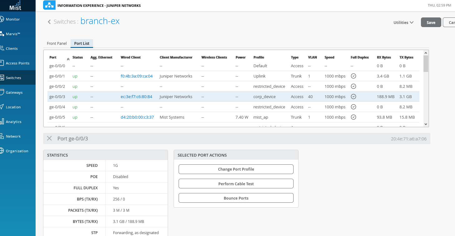
You have completed the configuration of the EX switch through the Juniper Mist Cloud. In the next section you claim and then configure your Mist AP in the Juniper Mist Cloud.
Day 1.5: Claim and Configure Mist AP in Juniper Mist Cloud
Overview of Mist Wi-Fi Assurance
Juniper Mist Wi-Fi Assurance, driven by machine learning on Juniper Mist, replaces manual troubleshooting tasks with automated wireless operations. This subscription service makes WLANs predictable, reliable, and measurable, all with unique visibility into the user experience. You can set up and track service-level thresholds for key wireless criteria connection metrics, such as time to connect, capacity, coverage, and throughput.
Juniper Mist Wi-Fi Assurance provides the industry’s most scalable guest access solution with flexible options including multiple language support, customizable branding, social login, external captive portal integration, and AAA/RADIUS integration.
Wireless Configuration on the Juniper Mist Cloud
Procedure
Step-by-step Procedure
You start by creating a wireless configuration template for the branch office. Click Organization > Config Templates in the left menu. Click the Create Template button and assign a template name. Here we again use the name “branch”.
Select whether you want to apply the template to the entire organization or to specific sites. For this example, we apply our configuration to the branch location.

-
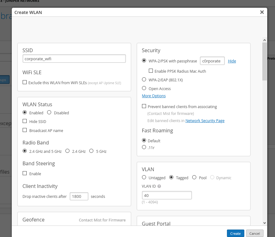
Create a WLAN template by clicking the Add WLAN button. We use this template to create an SSID (WLAN) for corporate devices in VLAN 40. Numerous options exist for a given SSID, to include a range of authentication mechanisms such as 802.1X, RADIUS, or a passphrase. For our example we use simple passphrase authentication. Be sure to select Tagged as the VLAN type and to specify a VLAN ID of 40.
-
Repeat the above step to define SSIDs for the IOT and the camera devices, using VLANs 20 and 30, respectively. When done your SSIDs should look like the example below:
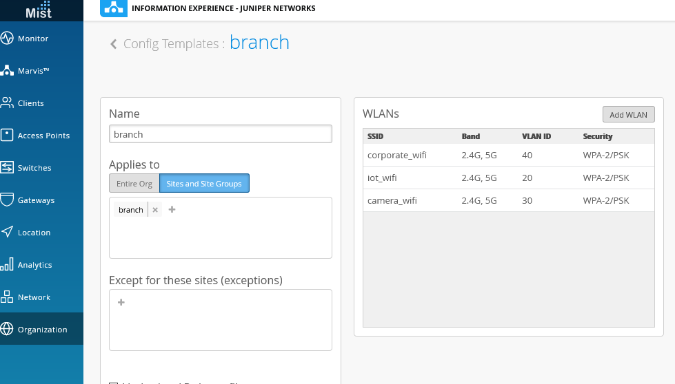
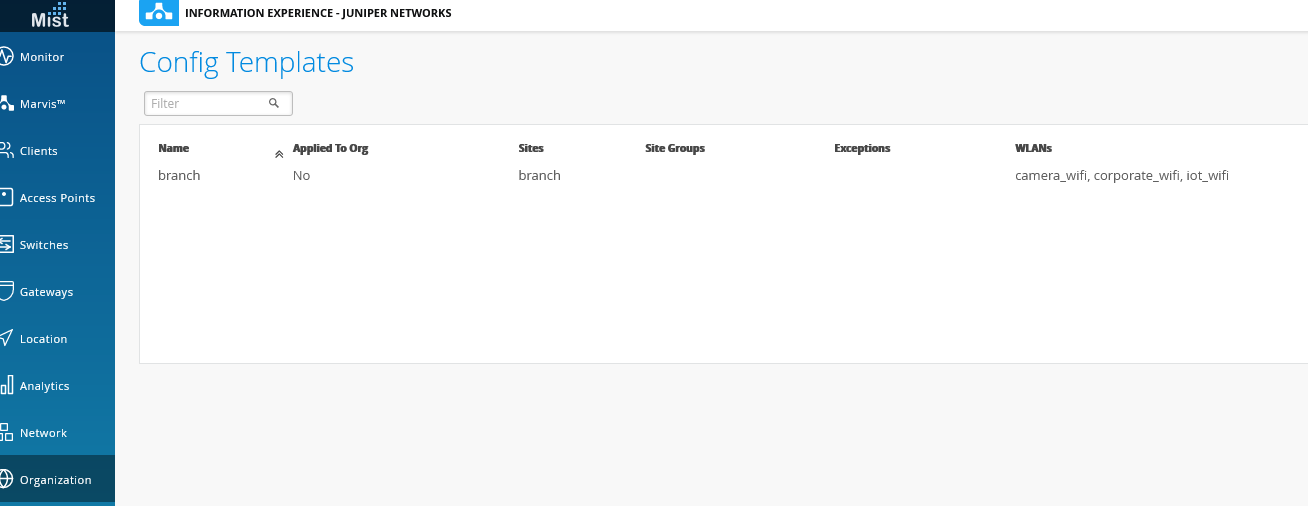
Be sure to save the changes to your template by clicking the Save button when finished. The display confirms that the configuration template is associated with the “branch” site.
-
In this step you claim the Mist AP to begin managing the device through the Juniper Mist Cloud. To claim an access point for the branch site, click on Access point in the menu on the left, and then on Claim APs. Enter the claim code on the Mist AP sticker, and add the AP to the “branch” site. When ready click on the Claim button. This displays the Claim Access Points and Activate Subscriptions confirmation dialog screen. Click Close to dismiss the confirmation window.
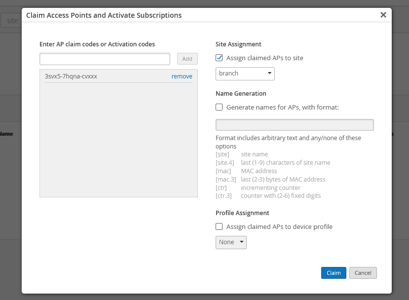
After a few moments the AP displays a green connected status. You might need to refresh your browser window.

If desired, click on the AP to view details about its configuration and operational status.
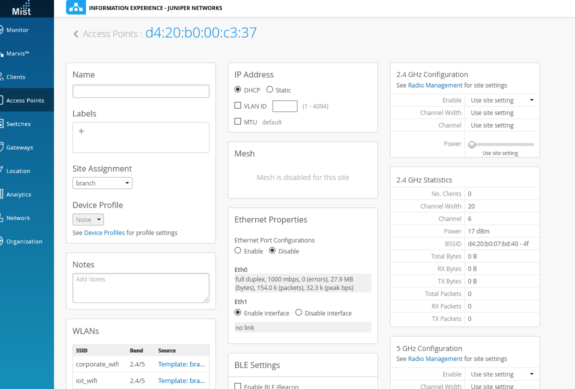
You have completed the configuration of the EX switch and the Mist AP through the Juniper Mist Cloud. In the next section you complete the configuration on the SRX to support the wired and wireless clients in addition to adding Application Quality Experience (AppQoE).
A Functional Branch Office
Congratulations! You have configured your SRX services gateway to support DHCP services and Internet access for the EX switch, the Mist AP, and the various corporate devices and their respective VLANs. You used this internet access to adopt/claim your switch and the AP into the Juniper Mist Cloud. You then configured both devices, leveraging the simplicity of configuration templates and the GUI interface.
You can view the resulting branch office topology by clicking on Switches in the left menu and then on the Topology tab. You can click on objects in the topology to display details about attached devices and their MAC addresses.
It might take some time for Juniper Mist Cloud to build up the topology through the exchange of analytical information with the site.
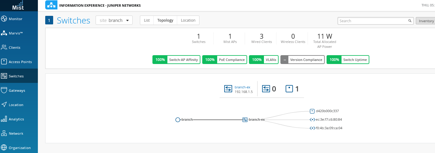
In the next section of this NCE you add sophisticated application based quality of services configuration to the SRX device to help ensure user experiences are compliant with your organizations SLAs.
