Unpack and Mount an ACX7100-32C Router
Unpack an ACX7100-32C Router
The ACX7100-32C router chassis is a rigid sheet-metal structure that houses the hardware components. An ACX7100-32C router is shipped in a cardboard carton, secured with foam packing material. The carton also contains an accessory box and quick start instructions.
ACX7100-32C routers are maximally protected inside the shipping carton. Do not unpack the router until you are ready to begin installation.
To unpack an ACX7100-32C router:
- Move the shipping carton to a staging area as close to the installation site as possible, where you have enough room to remove the system components.
- Position the carton so that the arrows are pointing up.
- Open the top flaps on the shipping carton.
- Remove the accessory box, and verify the contents against the inventory included in the box.
- Pull out the packing material that is holding the router in place.
- Verify the chassis components that you received.
- Save the shipping carton and packing materials in case you need to move or ship the router later.
Component |
Quantity |
|---|---|
Chassis with six fan modules and two PSMs |
1 |
AC power cord (generic, type C15 coupler) |
2 |
Power cord retainers |
2 |
Four-post rack mounting kit |
1 |
Documentation roadmap card |
1 |
We no longer include the RJ-45 console cable with the DB-9 adapter as part of the device package. If the console cable and adapter are not included in your device package, or if you need a different type of adapter, you can order the following separately:
-
RJ-45 to DB-9 adapter (JNP-CBL-RJ45-DB9)
-
RJ-45 to DB-9 adapter (JNP-CBL-RJ45-DB9)
-
RJ-45 to USB-C adapter (JNP-CBL-RJ45-USBC)
If you want to use RJ-45 to USB-A or RJ-45 to USB-C adapter you must have X64 (64-Bit) Virtual COM port (VCP) driver installed on your PC. See, https://ftdichip.com/drivers/vcp-drivers/ to download the driver.
Mount an ACX7100-32C Router in a Rack
You can mount an ACX7100-32C router on a rack using the mounting kit provided with the device.
Before You Begin Rack Installation
Before you begin mounting an ACX7100-32C router in the rack:
If you are mounting multiple units on a rack, mount the heaviest unit at the bottom of the rack and mount the other units from the bottom of the rack to the top in decreasing order of the weight of the units.
Install an ACX7100-32C Router in a Rack
To install the router in a four-post rack:
-
Align the holes in the front-mounting rails with the holes
on the side of the chassis (see Figure 1).
Figure 1: Install the Mounting Rails on an ACX7100-32C Router

-
Carefully slide the chassis with the rails attached on
to the rack rails (see Figure 2).
Figure 2: Install the ACX7100-32C Router in a Four-Post Rack

-
Install mounting screws into each of the front-mounting
bracket holes aligned with the rack, starting from the bottom, and
tighten the screws. Figure 3 shows the router fully secured to the front rails of the
four-post rack.
Figure 3: ACX7100-32C Router Secured by Front-Mounting Brackets

-
On the rear of the chassis, slide the rear-mounting blades
on either side of the chassis until the rear-mounting brackets at
the end of the blades contact the rack rails (see Figure 4).
The rear-mounting blades on each side of the chassis are movable. You can adjust the length of the blades according to the depth of the rack.
Figure 4: Install the Rear-Mounting Blades on an ACX7100-32C Router
-
Visually inspect the alignment of the chassis.
If you’ve installed the chassis properly in the rack, all the mounting screws on one side of the rack are aligned with the mounting screws on the opposite side, and the router is level. Figure 5 shows the router fully secured and installed in a four-post rack.
Figure 5: ACX7100-32C Router Installed in a Four-Post Rack
Mount an ACX7100-32C Router in a Rack or Cabinet by Using the JNP-4PST-RMK-1U-E Rack Mount Kit
You can mount ACX7100-32C Routers on a square hole or threaded hole four-post 19-in. racks using the partial tool less JNP-4PST-RMK-1U-E rack mount kit.
JNP-4PST-RMK-1U-E rack mount kit consists of the following parts:
-
A pair of front and rear mounting rails
-
A pair of mounting brackets
-
16 flat head M4 x 6mm Phillips screws
A four-post installation evenly supports the device by all four corners.
- Mount the Device by Using the JNP-4PST-RMK-1U-E Rack Mount Kit On a Square Hole Rack
- Mount the Device by Using the JNP-4PST-RMK-1U-E Rack Mount Kit On a Threaded Hole Rack
Mount the Device by Using the JNP-4PST-RMK-1U-E Rack Mount Kit On a Square Hole Rack
Ensure that you have the following tools and parts available:
-
An ESD grounding strap—not provided.
-
Number 2 Phillips (+) screwdriver—not provided
-
A pair of front and rear mounting rails that attach to the rack posts—provided with the rack mount kit
-
A pair of mounting brackets and 16 flat head M4 x 6mm Phillips screws. These brackets attach to the device if not pre-installed—provided with the rack mount kit
To mount the device on four posts in a rack by using the JNP-4PST-RMK-1U-E rack mount kit:
- Assemble the mounting rails.
-
Attach the mounting rails to the rack.
-
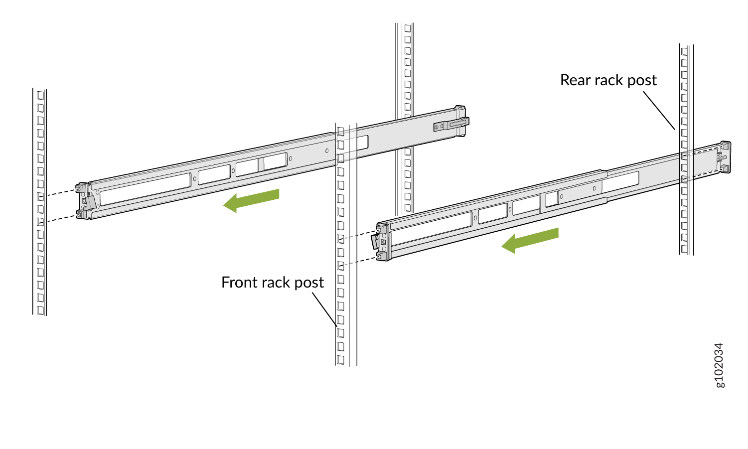
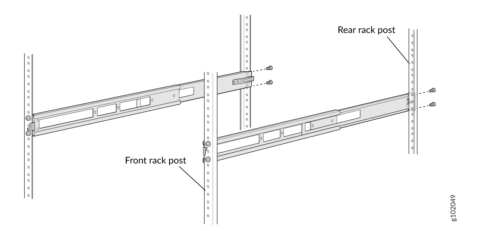
Align the guide blocks of the rear mounting rails with the rear-post holes. Pull
the rear mounting rails toward the front of the rack to lock the rails in place. You
will hear a click sound when the latch locks into the corresponding rack holes. See
Figure 8.
Figure 8: Install the Rear Floating Rails
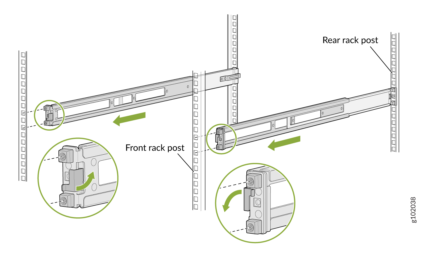
-
Move the latch lock on the front mounting rails to open position, slide the front
mounting rails, and insert the guide blocks into the front rack posts. See Figure 9.
Figure 9: Install the Front Mounting Rails
-
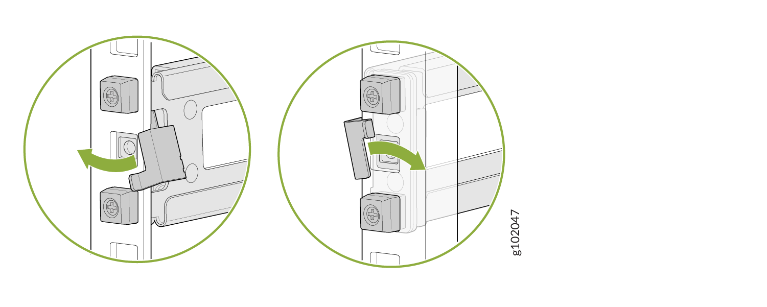
Push the lock latch to the locked position. See Figure 10.
Figure 10: Front Mounting Rails Lock Latch
-
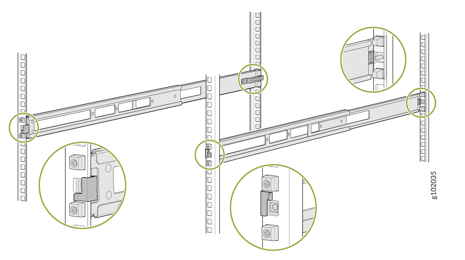
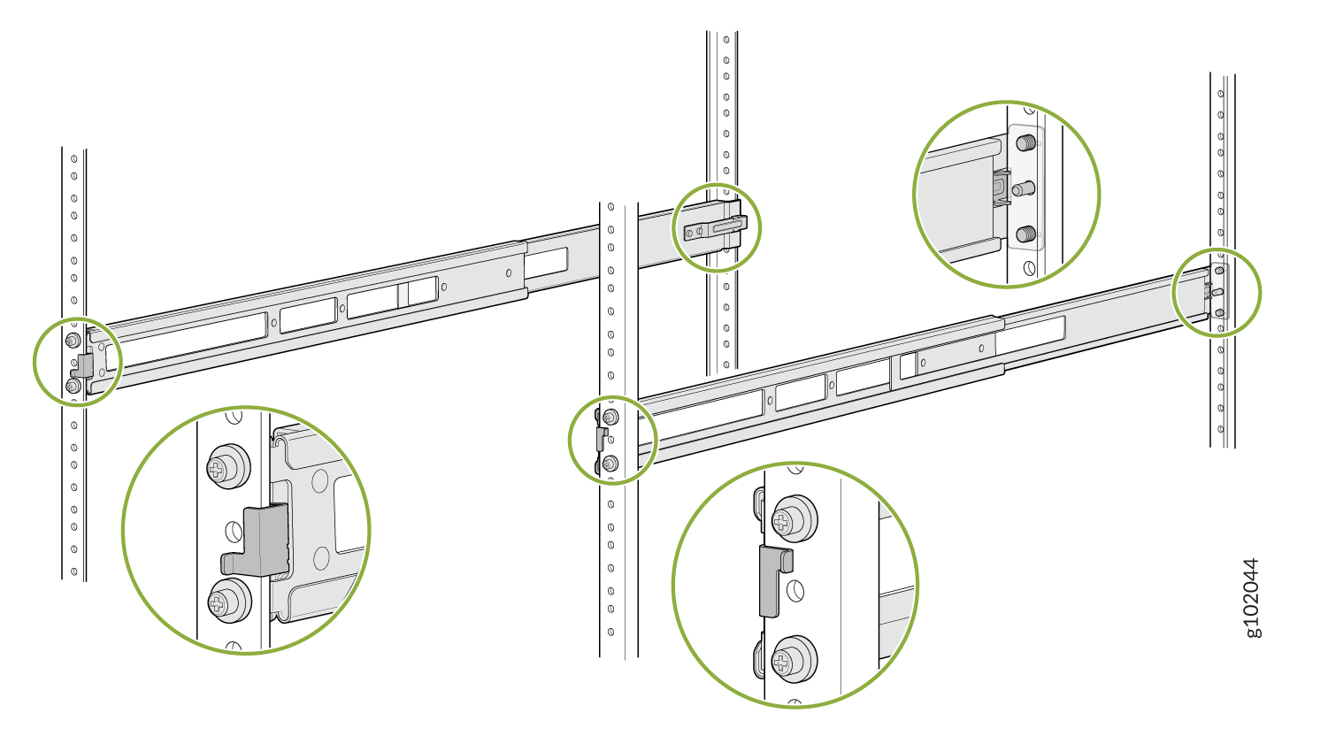
Visually ensure that the front and rear latches are locked into place on the
mounting rails. See Figure 11.
Figure 11: Mounting Rails Installed and Locked
-
Align the guide blocks of the rear mounting rails with the rear-post holes. Pull
the rear mounting rails toward the front of the rack to lock the rails in place. You
will hear a click sound when the latch locks into the corresponding rack holes. See
Figure 8.
-
Attach mounting brackets to the device if not pre-installed. If your device already has
the mounting brackets pre-installed than skip this step and move to the next step.
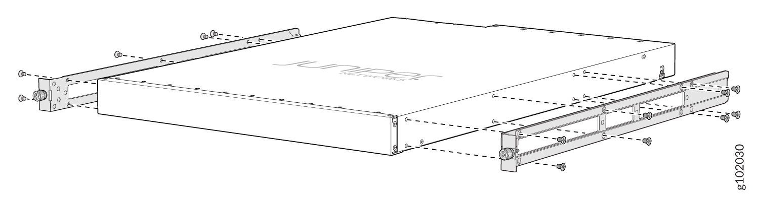
-
Insert the flat head M4 x 6mm Phillips screws to attach the mounting bracket into
the aligned holes on the chassis (see Figure 12). Tighten the screws.
Figure 12: Attach the Mounting Brackets to the Device
-
Insert the flat head M4 x 6mm Phillips screws to attach the mounting bracket into
the aligned holes on the chassis (see Figure 12). Tighten the screws.
-
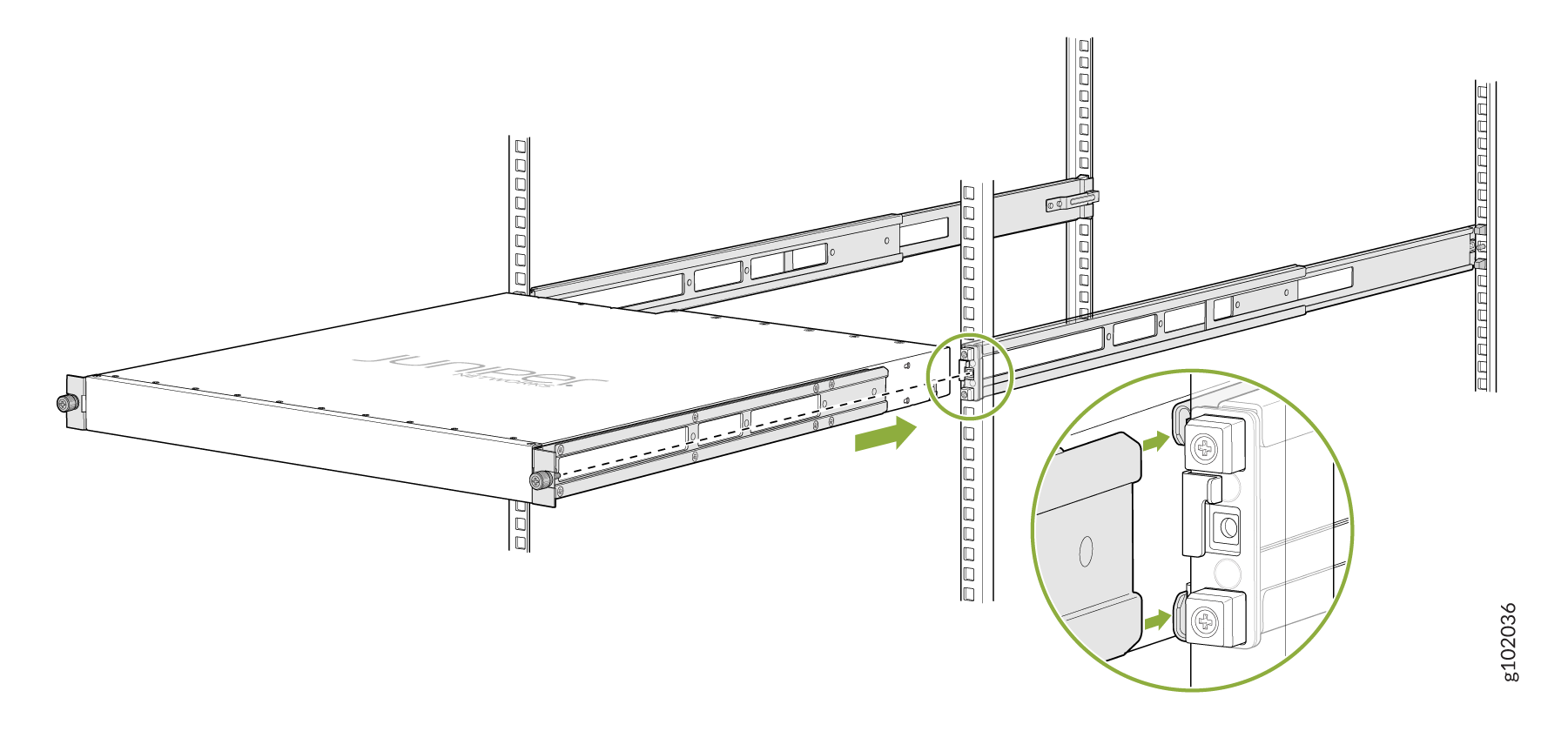
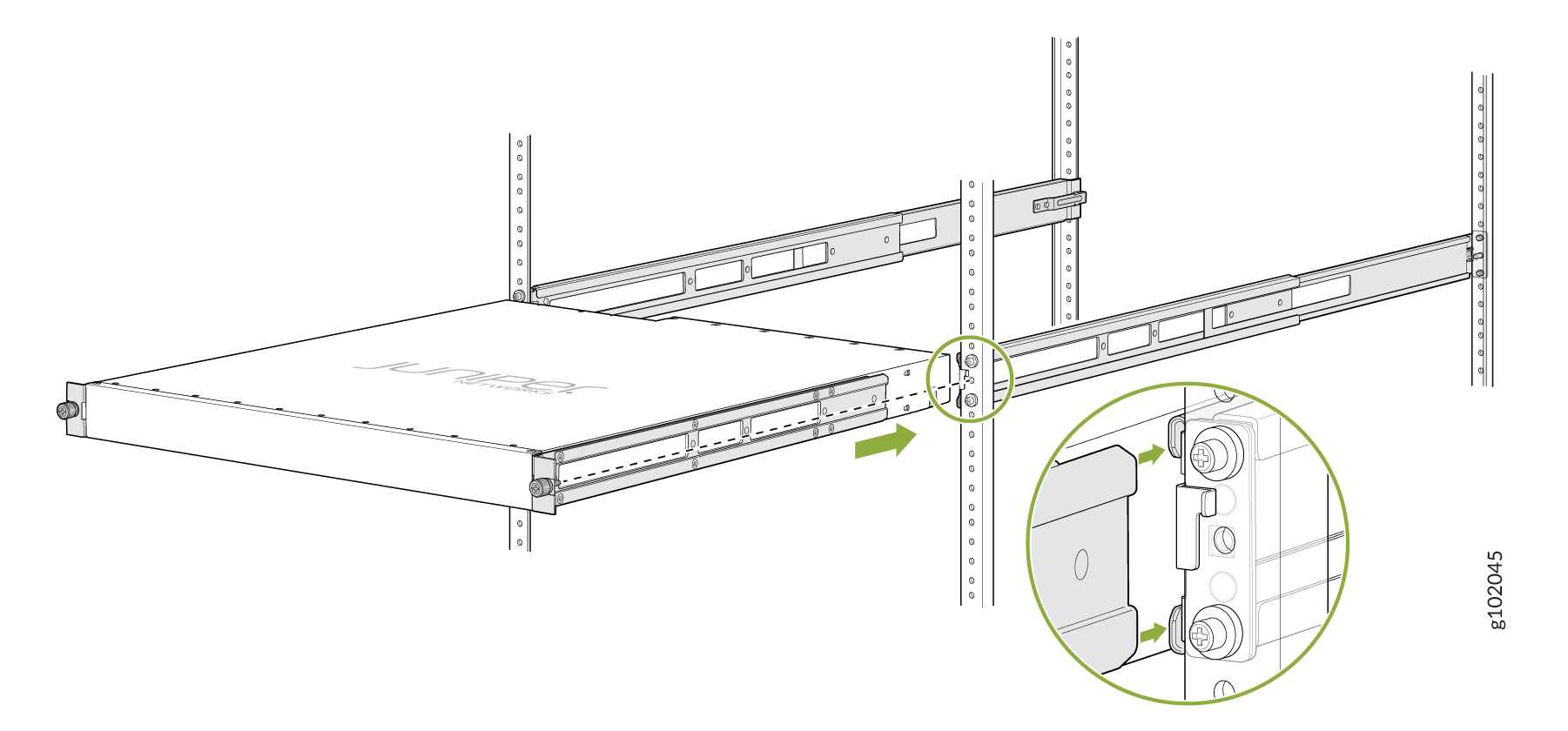
Grasp both sides of the device, lift it, and position the device such that the mounting
rails slide into the channels of the mounting brackets. See Figure 13.
Figure 13: Slide the Device into the Rack
-
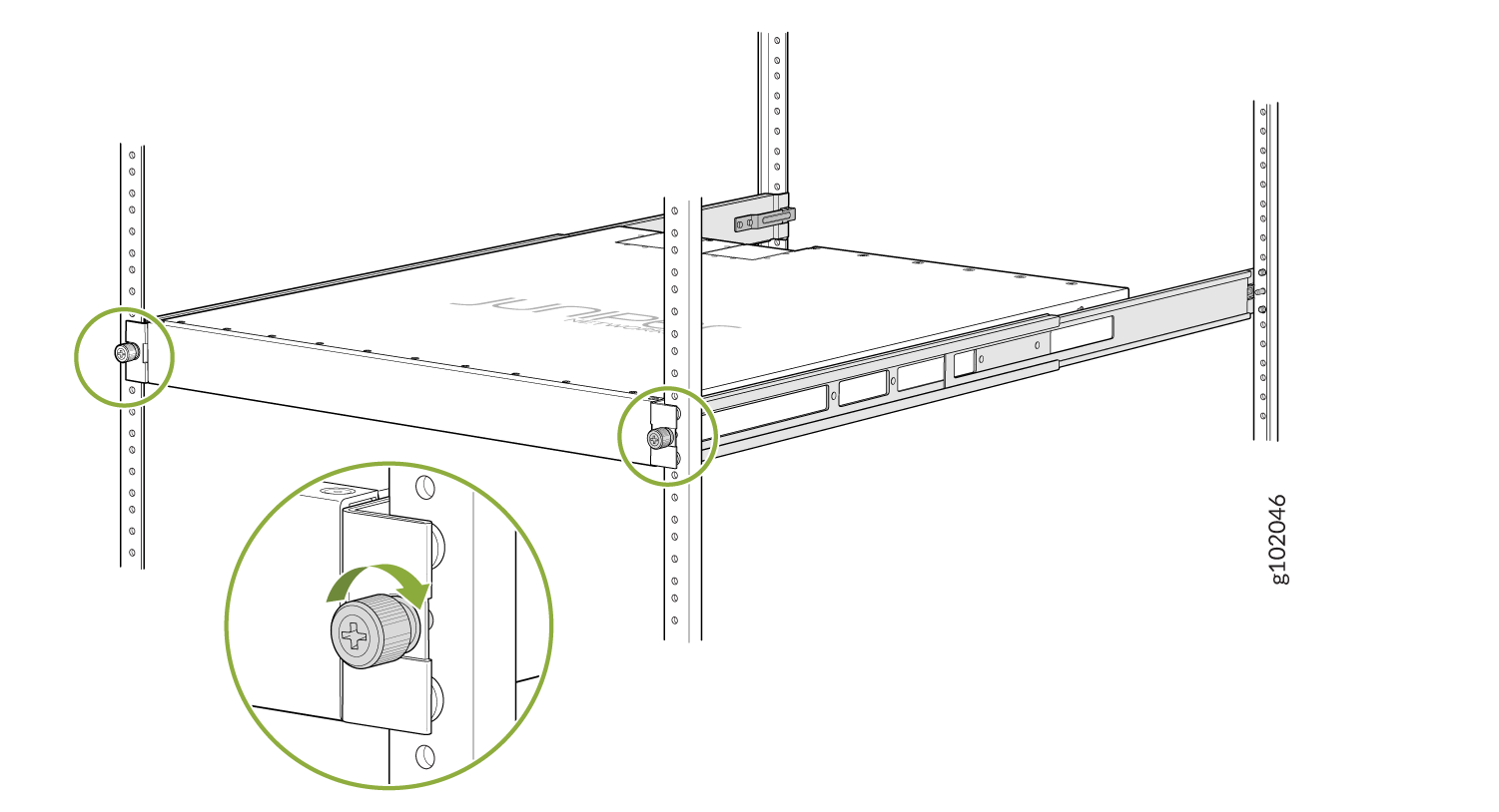
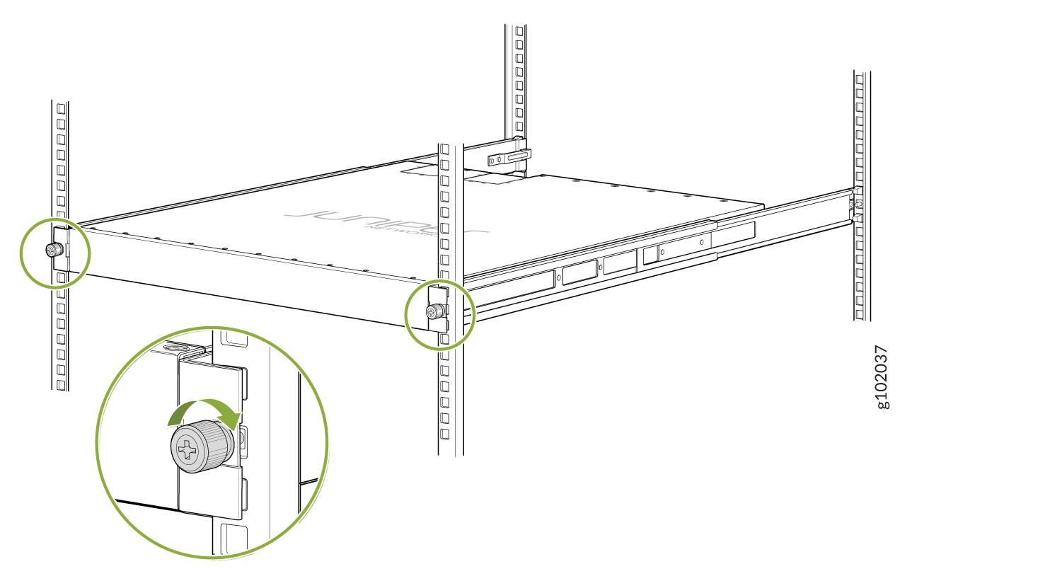
Tighten the two thumbscrews to secure the device. See Figure 14.
Figure 14: Tighten the Thumb Screws
Mount the Device by Using the JNP-4PST-RMK-1U-E Rack Mount Kit On a Threaded Hole Rack
Ensure that you have the following tools and parts available:
-
An ESD grounding strap—not provided
-
Number 2 Phillips (+) screwdriver—not provided
-
A pair of front and rear mounting rails that attach to the rack posts—provided with the rack mount kit
-
A pair of side mounting brackets and 16 flat head M4 x 6mm Phillips screws. These brackets attach to the device if not pre-installed—provided with the rack mount kit
To mount the device on four posts in a threaded hole rack by using the JNP-4PST-RMK-1U-E rack mount kit:
-
Assemble the mounting rails.
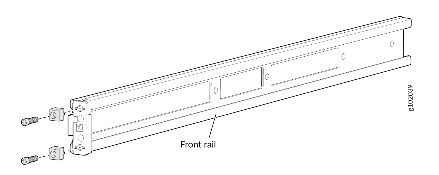
-
Remove the guide blocks from the front mounting rails by loosening the screws and
preserve them for later use. See Figure 15.
Figure 15: Remove Guide Blocks from Front Mounting Rail
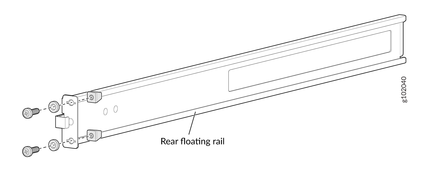
-
Remove the guide blocks from the rear floating rails by loosening the screws and
washers. Preserve the guide blocks, screws, and washers for later use. See Figure 16
Figure 16: Remove Guide Blocks from Rear Floating Rail
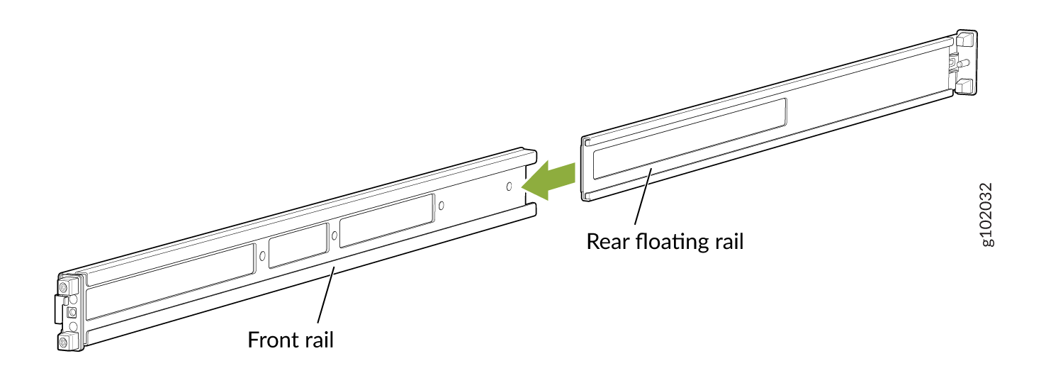
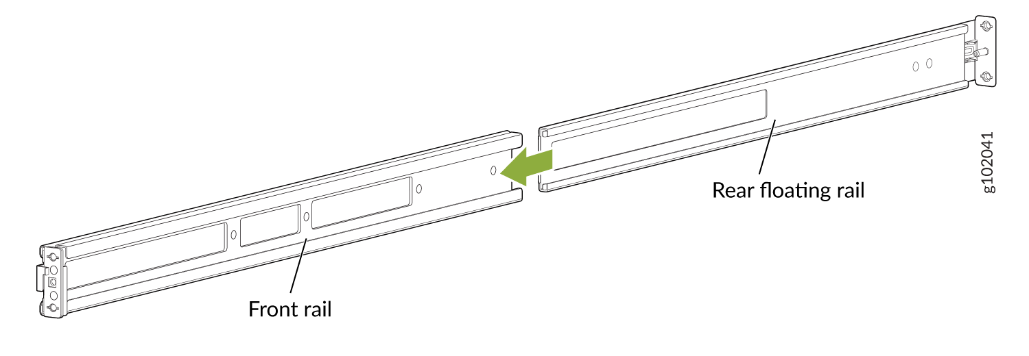
-
Slide the rear floating rails into the front mounting rails. See Figure 17.
Figure 17: Slide Rear Floating Rail into Front Mounting Rail
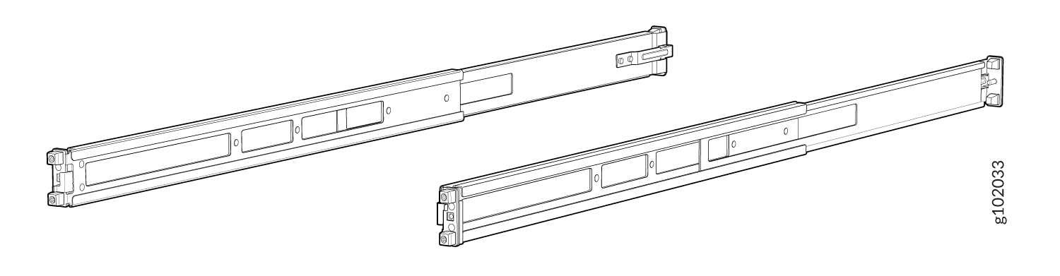
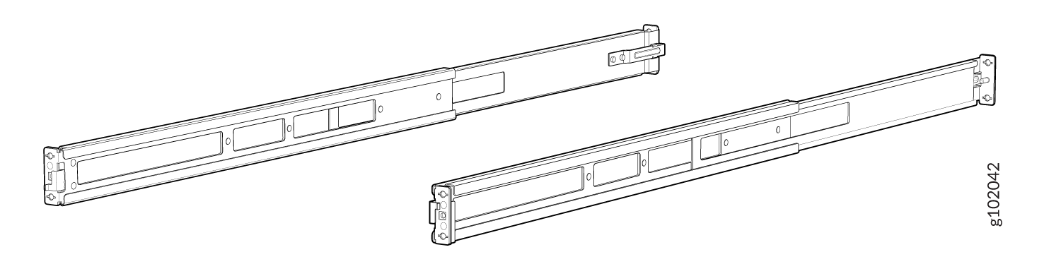
-
Mounting rails assembled. See Figure 18.
Figure 18: Front and Rear Rails Assembled
-
Remove the guide blocks from the front mounting rails by loosening the screws and
preserve them for later use. See Figure 15.
-
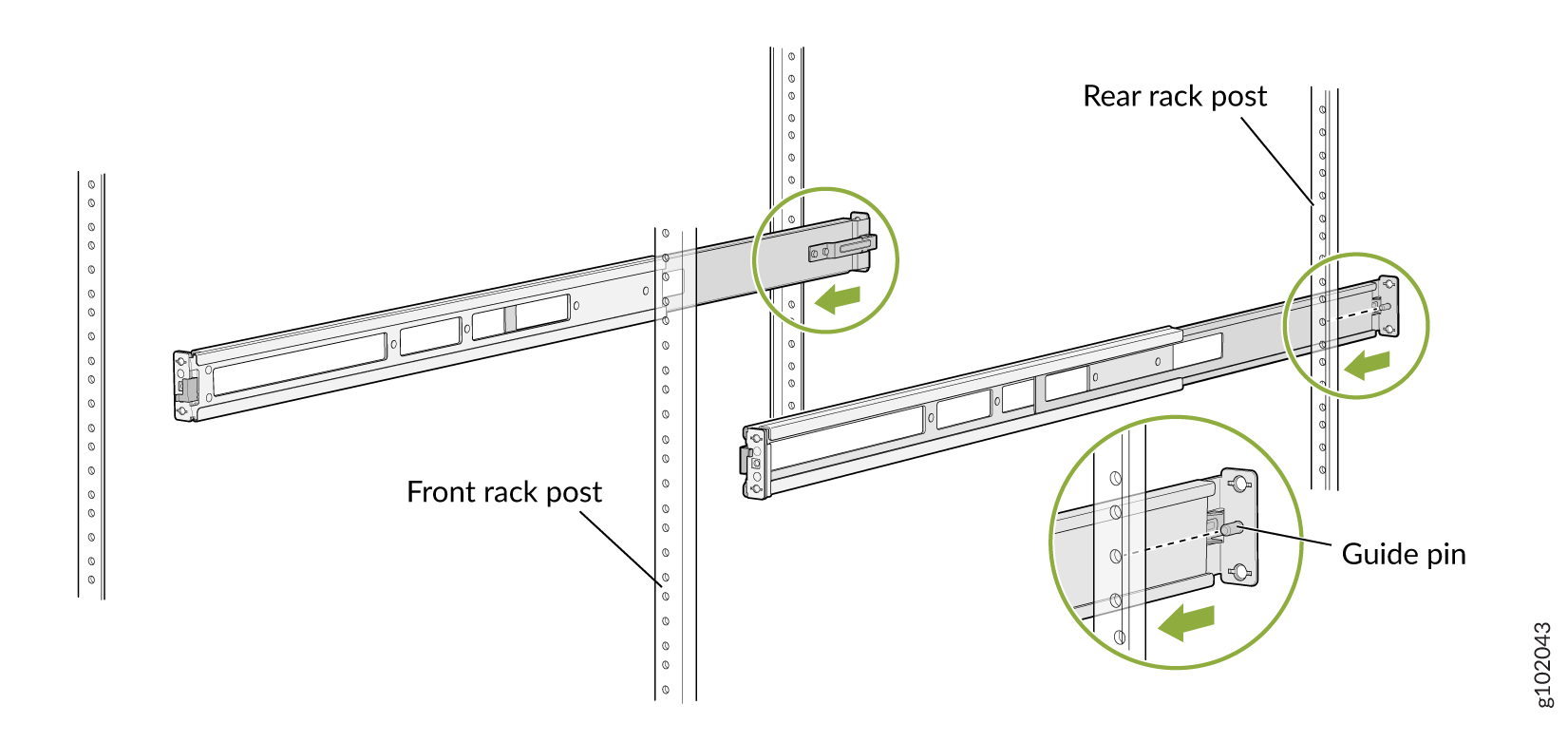
Attach the mounting rails to the threaded hole rack.
-
Align the guide blocks of the rear mounting rails with the rear-post holes. Pull
the rear mounting rails toward the front of the rack to lock the rails in place. You
will hear a click sound when the latch locks into the corresponding rack holes. See
Figure 19.
Figure 19: Install the Rear Floating Rails
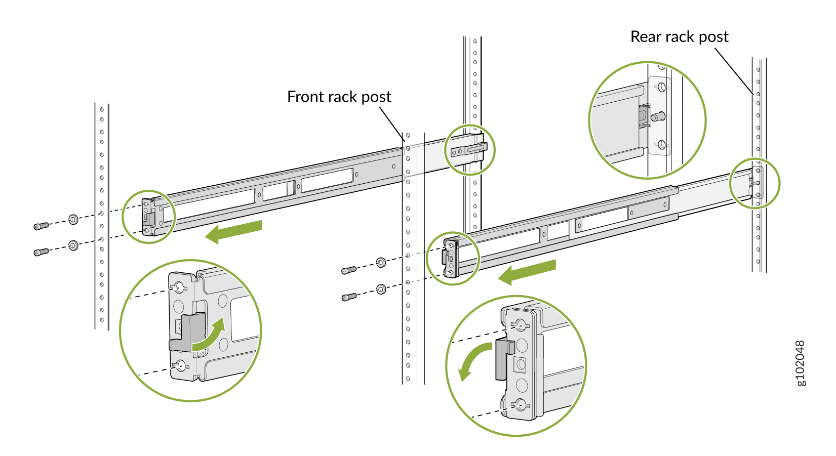
-
Move the latch locks on the front mounting rails to open position, slide the front
mounting rails and align them to the front rack post. Push the lock latch to locked
position and using the screws removed in step 2.a and
the washers removed in step 2.b,
secure the front mounting rails to the front rack post. See Figure 20.
Figure 20: Install the Front Mounting Rails
-
Secure the rear floating rails to the rear rack post by using screws (not provided)
appropriate for your rack threaded size. See Figure 21.
Figure 21: Secure the Rear Floating Rails
-
Visually ensure that the front and rear latches are locked into place on the
mounting rails. See Figure 22.
Figure 22: Mounting Rails Installed and Secured
-
Align the guide blocks of the rear mounting rails with the rear-post holes. Pull
the rear mounting rails toward the front of the rack to lock the rails in place. You
will hear a click sound when the latch locks into the corresponding rack holes. See
Figure 19.
-
Attach mounting brackets to the device if not pre-installed. If your device already has
the mounting brackets pre-installed than skip this step and move to the next step.
-
Insert the flat head M4 x 6mm Phillips screws to attach the mounting bracket into
the aligned holes on the chassis (see Figure 23). Tighten the screws.
Figure 23: Attach the Mounting Brackets to the Device
-
Insert the flat head M4 x 6mm Phillips screws to attach the mounting bracket into
the aligned holes on the chassis (see Figure 23). Tighten the screws.
-
Grasp both sides of the device, lift it, and position the device such that the mounting
rails slide into the channels of the mounting brackets. See Figure 24.
Figure 24: Slide the Device into the Rack
-
Tighten the two thumbscrews to secure the device. See Figure 25.
Figure 25: Tighten Thumb Screws