CTP2008 Platform
The Juniper Networks CTP2008 Circuit to Packet platform has one removable interface module and one removable processor module, and is available in both AC-powered and DC-powered versions. Fans are located at the sides of the chassis and hence the airflow is side-to-side. Unlike CTP2024 and CTP2056 chassis, the CTP2008 fans are fixed in the chassis and not part of a removable tray.
PP310 is a Generation 1 or Gen 1 CPU.PP332 is a Generation 2 or Gen 2 CPU.PP833 is a Generation 3 or Gen 3 CPU.PPF84 is a Generation 4 or Gen 4 CPU.
The generation of the CTP system (that is, which CPU was in the purchased CTP2000 system) is indicated in the suffix of the model number. Example: CTP2008-AC-04 is a Gen 4 system with PPF84 CPU.
Figure 2, Figure 3, and Figure 4 show the CTP2008 chassis containing the PP332 (Gen 2 CPU) processor (which requires an RTM card for Ethernet and console port accesses). The new PPF84 (Gen 4 CPU) Figure 1 or PP833 (Gen 3 CPU) processor module does not require an RTM card as the module itself contains Ethernet and USB-connector-type Console ports. If you are upgrading from the old PP310 (Gen 1 CPU) or PP332 (Gen 2 CPU) processor to the PPF84 (Gen 4 CPU) or PP833 (Gen 3 CPU) processor, the RTM card may be left in the node. But, none of the interfaces (Ethernet or serial ports) on the RTM panel are functional. If you want to upgrade from PP833 (Gen 3 CPU) processor to PPF84 (Gen 4 CPU) processor, see Upgrading from PP833 to PPF84 Processor.
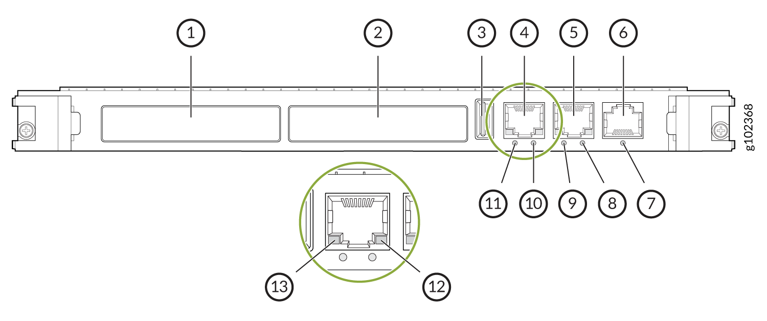
The front panel of the PPF84 processor comprises the following components:
1 — XMC1—Both XMC slots are available to support compatible fiber XMC modules. For more information about the XMC module, see CTP2000 XMC Module and Installing and Removing XMC Module. | 7 — LED indicating the status of the COM 1 port. This LED is used when the board is hot-swapped, and lights blue to indicate when the board can be safely removed from the chassis. |
2 — XMC2 | 8 — LED indicating the status of the Ethernet-2 port speed. This LED lights yellow when there is activity on the M.2 interface if supported by the M.2 module fitted. This LED is driven by a signal from the M.2 module but not all M.2 modules drive the signal. |
3 — USB 2.0 | 9 — LED indicating the status of the Ethernet-2 port link/activity. This LED flashes red rapidly when the CPU reaches it maximum specified operating temperature |
4 — Ethernet port 1—Provides the 1-Gbps Ethernet connection to the IP network by means of a local Ethernet switch or router. | 10 — LED indicating the status of the Ethernet-1 port speed. This POST LED is used to indicate that a power on self-test has failed. This LED will also flash when outputting sound on the speaker. The LED will be OFF when the board is in reset, power cycling or powered down/in sleep state. |
5 — Ethernet port 2 | 11 — LED indicating the status of the Ethernet-1 port link/activity. This Run LED lights green to indicate and assess processor activity. |
6 — COM 1—(RJ45) Provides an asynchronous tty connection for locally configuring the CTP Series device. |
The PPF84 processor does not support PMC card.
The front panel comprises the following components (see Figure 2):
-
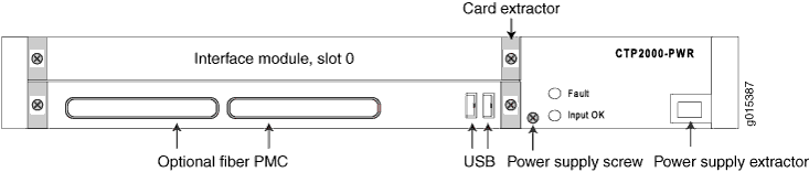
Interface module—Include customer facing revenue interfaces, with frame processing and forwarding engines.
-
Processor module—This is the system controller. There are two optional fiber PMC (PCI mezzanine card) locations at the top for inserting SFP PMC modules. For more information about the PMC module, see CTP2000 PMC Module and Installing a PMC on CTP2000 Platforms.
-
Power supply—To extract, loosen power supply screw, push the extractor button, and lift lever to eject the power supply module.
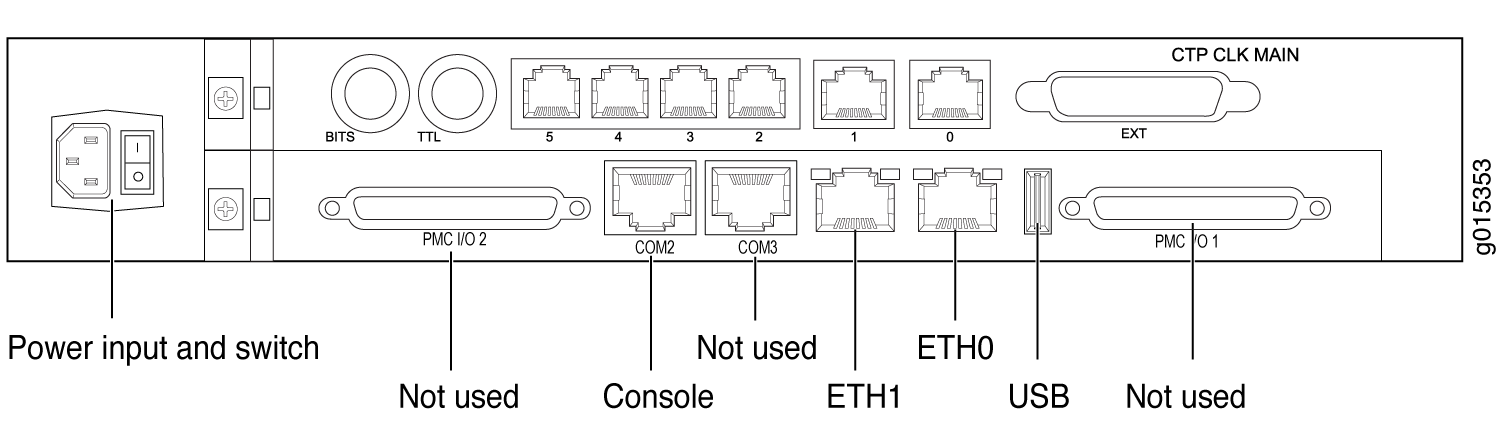
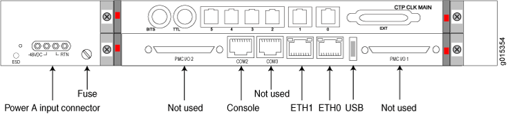
The rear panel comprises the following components (see Figure 3 and Figure 4):
-
CPU RTM module—This Rear Transition Module (RTM) goes behind PP310/PP332 (Gen1/Gen2) CPU card only. Otherwise, it is not used and can be removed. If used, it has the following interfaces:
-
Ethernet connection—Provides the 1-Gbps Ethernet connection to the IP network by means of a local Ethernet switch or router.
-
Console connection—Provides an asynchronous tty connection for locally configuring the CTP Series device. On the PP310 and PP332 processors, you can connect a console directly to the COM2 port (which is an RJ-45 type connector) found on the RTM panel.
Note:The CPU RTM RJ45 console pinout is different from other RJ45 console pinouts. See CTP2000 Series Console Cable Pinouts
-
USB: Can be used for software updates.
-
-
Clock module—This Rear Transition Module (RTM) goes behind interface module slot 0, and provides RS422, BITS, and TTL clock inputs for physical clock references. It also provides clock distribution between modules when the backplane is in use by voice applications.
-
Power input—Use a standard IEC power cord for the AC version. Use a 22-AWG fork terminal connector for the DC version. There is no power redundancy for the AC version and the DC version.
Note:There are no power switches on CTP2000 Series DC models, so a readily accessible disconnect device must be provided as part of the electrical installation of the unit. We recommend the 22-AWG wire for DC power terminals.