Dynamic Load Balancing (DLB)
Learn about Dynamic load balancing (DLB) and how to configure DLB. This topc also includes how to configure DLB for ECMP and LAG.
Dynamic Load Balancing (DLB) Overview
Load balancing ensures that network traffic is distributed as evenly as possible across members in a given equal-cost multipath (ECMP) routing group or LAG. In general, load balancing is classified as either static or dynamic. Static load balancing (SLB) computes hashing solely based on the packet contents (for example, source IP, destination IP, and so on). The biggest advantage of SLB is that packet ordering is guaranteed as all packets of a given flow take the same path. However, because the SLB mechanism does not consider the path or link load, the network often experiences the following problems:
-
Poor link bandwidth utilization
-
Elephant flow on a single link completely dropping mice flows on it.
Dynamic load balancing (DLB) is an improvement on top of SLB.
For ECMP, you can configure DLB globally, whereas for LAG, you configure it for each aggregated Ethernet interface (aex). You can apply DLB on selected ether-type (Dynamic Load Balancing) (IPv4, IPv6, and MPLS) based on configuration. If you don't configure any ether-type (Dynamic Load Balancing), then DLB is applied to all EtherTypes. Note that you must explicitly configure the DLB mode as default mode is absent.
Use Feature Explorer to confirm platform and release support for specific features.
-
You cannot configure both DLB and resilient hashing at the same time. Otherwise, a commit error will be thrown.
-
DLB is applicable only for unicast traffic.
-
DLB is not supported when the LAG is one of the egress ECMP members.
-
DLB is not supported for remote LAG members.
-
DLB is not supported on Virtual Chassis and VCF.
-
DLB on LAG and HiGig-trunk are not supported at the same time.
Following are the important behaviors of DLB:
-
DLB is applicable for incoming EtherTypes only.
-
From a DLB perspective, both L2 and L3 LAG bundles are considered the same.
-
The link utilization will not be optimal if you use DLB in asymmetric bundles—that is, on ECMP links with different member capacities.
-
With DLB, no reassignment of flow happens when a new link is added in per packet and assigned flow modes. This can cause suboptimal usage in link flap scenarios where a utilized link might not be utilized after it undergoes a flap if no new flow or flowlets are seen after the flap.
Benefits
-
DLB considers member bandwidth utilization along with packet content for member selection. As a result, we achieve better link utilization based on real-time link loads.
-
DLB ensures that links hogged by elephant flows are not used by mice flows. Thus, by using DLB, we avoid hash collision drops that occur with SLB. That is, with DLB the links are spread across, and thus the collision and the consequent drop of packets are avoided.
DLB Modes
You can use the following DLB modes to load-balance traffic:
-
Per packet mode
In this mode, DLB is initiated for each packet in the flow. This mode makes sure that the packet always gets assigned to the best-quality member port. However, in this mode, DLB might experience packet reordering problems that can arise due to latency skews.
-
Flowlet mode
The flowlets mode assigns links based on "flowlets," which are essentially bursts of data within a single traffic flow. This happens because upper-layer protocols, like TCP, often pause and restart the data transmission, creating these bursts.
Inactivity interval
The pause between each flowlet is called the inactivity interval. You can configure this setting, and it tells the system when a new flowlet has begun. This allows the system to initiate load balancing for both new and existing flows that have been inactive for a while.
Avoid packet reordering
A key benefit of this method is that it prevents packet reordering. All packets within a single flowlet are sent over the same link. By setting the inactivity-interval value to be higher than the maximum latency, you can avoid reordering across different flowlets while making full use of all available links.
-
Assigned flow mode
You can use assigned flow mode to selectively disable rebalancing for a period of time to isolate problem sources. You cannot use this mode for real-time DLB. You cannot predict the egress ports that will be selected using this mode because assigned flow mode does not consider port load and queue size.
Configuring Dynamic Load Balancing
This topic describes how to configure dynamic load balancing (DLB) in flowlet mode.
Configure DLB for ECMP (Flowlet mode)
To configure dynamic load balancing for ECMP with flowlet mode (QFX5120-32C, QFX5120-48Y, and QFX5220 switches):
Similarly, you can configure DLB for ECMP with Per packet or Assigned flow mode.
Configure DLB for LAG (Flowlet mode)
Before you begin, create an aggregated Ethernet bundle by configuring a set of router interfaces as aggregated Ethernet and with a specific aggregated Ethernet group identifier.
To configure dynamic load balancing for LAG with flowlet mode (QFX5120-32C and QFX5120-48Y):
Enable dynamic load balancing with flowlet mode:
[edit interfaces ae-x aggregated-ether-options]
user@router# set dlb flowlet
(Optional) Configure the inactivity-interval value - minimum inactivity interval (in micro seconds) for link re-assignment:
[edit interfaces ae-x aggregated-ether-options]
user@router# set dlb flowlet inactivity-interval (micro seconds)
(Optional) Configure dynamic load balancing with
ether-type:[edit forwarding-options enhanced-hash-key] user@router# set lag-dlb ether-type mpls
(Optional) You can view the options configured for dynamic load balancing on LAG using
show forwarding-options enhanced-hash-keycommand.
Similarly, you can configure DLB for LAG with Per packet or Assigned flow mode.
Example: Configure Dynamic Load Balancing
This example shows how to configure dynamic load balancing.
Requirements
This example uses the following hardware and software components:
Two QFX5120-32C or QFX5120-48Y switches
Junos OS Release 19.4R1 or later running on all devices
Overview
Dynamic load balancing (DLB) is an improvement on top of SLB.
For ECMP, you can configure DLB globally, whereas for LAG, you configure it for each aggregated Ethernet interface. You can apply DLB on selected EtherTypes such as IPv4, IPv6, and MPLS based on configuration. If you don't configure any EtherType, then DLB is applied to all EtherTypes. Note that you must explicitly configure the DLB mode because there is no default mode.
You cannot configure both DLB and Resilient Hashing at the same time. Otherwise, commit error will be thrown.
Topology
In this topology, both R0 and R1 are connected.
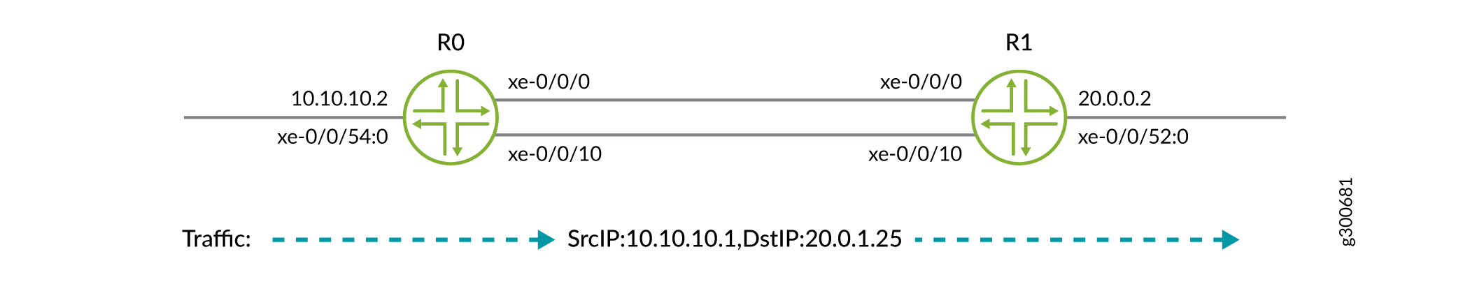
This example shows static configuration. You can also add configuration with dynamic protocols.
Configuration
- CLI Quick Configuration
- Configure Dynamic Load Balancing for LAG (QFX5120-32C and QFX5120-48Y)
- Configure Dynamic Load Balancing for ECMP (QFX5120-32C, QFX5120-48Y, and QFX5220 switches)
CLI Quick Configuration
To quickly configure this example, copy the following commands, paste them into a text file, remove any line breaks, change any details necessary to match your network configuration, and then copy and paste the commands into the CLI at the [edit] hierarchy level.
R0
set interfaces xe-0/0/0 unit 0 family inet address 10.1.0.2/24
set interfaces xe-0/0/10 unit 0 family inet address 10.1.1.2/24
set interfaces xe-0/0/54:0 unit 0 family inet address 10.10.10.2/24
set forwarding-options enhanced-hash-key ecmp-dlb per-packet
set policy-options policy-statement loadbal then load-balance per-packet
set routing-options static route 20.0.1.0/24 next-hop 10.1.0.3
set routing-options static route 20.0.1.0/24 next-hop 10.1.1.3
set routing-options forwarding-table export loadbal
R1
set interfaces xe-0/0/0 unit 0 family inet address 10.1.0.3/24
set interfaces xe-0/0/10 unit 0 family inet address 10.1.1.3/24
set interfaces xe-0/0/52:0 unit 0 family inet address 20.0.0.2/16
Configure Dynamic Load Balancing for LAG (QFX5120-32C and QFX5120-48Y)
Step-by-Step Procedure
The following example requires you to navigate various levels in the configuration hierarchy. For information about navigating the CLI, see Using the CLI Editor in Configuration Mode.
To configure the R0 router:
Repeat this procedure for the other routers, after modifying the appropriate interface names, addresses, and any other parameters for each router.
Configure Link Aggregation Group (LAG).
[edit interfaces]user@R0# set interfaces xe-0/0/0 ether-options 802.3ad ae0 user@R0# set interfaces xe-0/0/10 ether-options 802.3ad ae0 user@R0# set interfaces ae0 aggregated-ether-options lacp active user@R0# set interfaces ae0 unit 0 family inet address 10.1.0.2/24 user@R0# set routing-options static route 20.0.1.0/24 next-hop 10.1.0.3After configuring LAG, in the verification section, execute the steps in the Verifying Traffic Load before configuring Dynamic Load Balancing Feature on LAG section, to check the configuration or the traffic load before configuring DLB.
Configure Dynamic Load Balancing with per-packet mode for LAG.
[edit]user@R0# set interfaces ae0 aggregated-ether-options dlb per-packetAfter configuring the DLB, in the verification section, execute the steps in the Verifying Traffic Load after configuring Dynamic Load Balancing Feature on LAG section, to check the configuration or the traffic load before configuring DLB.
Configure Dynamic Load Balancing for ECMP (QFX5120-32C, QFX5120-48Y, and QFX5220 switches)
Step-by-Step Procedure
The following example requires you to navigate various levels in the configuration hierarchy. For information about navigating the CLI, see Using the CLI Editor in Configuration Mode.
To configure the R0 router:
Repeat this procedure for the other routers, after modifying the appropriate interface names, addresses, and any other parameters for each router.
Configure the Gigabit Ethernet interface link connecting from R0 to R1.
[edit interfaces]user@R0# set interfaces xe-0/0/0 unit 0 family inet address 10.1.0.2/24 user@R0# set interfaces xe-0/0/10 unit 0 family inet address 10.1.1.2/24 user@R0# set interfaces xe-0/0/54:0 unit 0 family inet address 10.10.10.2/24Create the static routes:
[edit interfaces]user@R0# set routing-options static route 20.0.1.0/24 next-hop 10.1.0.3 user@R0# set routing-options static route 20.0.1.0/24 next-hop 10.1.1.3Apply the load-balancing policy. The dynamic load balancing feature requires the multiple ECMP next hops to be present in the forwarding table.
[edit interfaces]user@R0# set policy-options policy-statement loadbal then load-balance per-packet user@R0# set routing-options forwarding-table export loadbalConfigure Dynamic Load Balancing with per-packet mode for ECMP.
[edit interfaces]user@R0# set forwarding-options enhanced-hash-key ecmp-dlb per-packetOn R1, configure the Gigabit Ethernet interface link.
[edit interfaces]user@R2# set interfaces xe-0/0/0 unit 0 family inet address 10.1.0.3/24 user@R2# set interfaces xe-0/0/10 unit 0 family inet address 10.1.1.3/24 user@R2# set interfaces xe-0/0/52:0 unit 0 family inet address 20.0.0.2/16
Verification
Confirm that the configuration is working properly.
- Verify Traffic Load Before Configuring Dynamic Load Balancing Feature on LAG
- Verify Traffic Load After Configuring Dynamic Load Balancing Feature on LAG
Verify Traffic Load Before Configuring Dynamic Load Balancing Feature on LAG
Purpose
Verify before the DLB feature is configured on the Link Aggregation Group.
Action
From operational mode, run the show interfaces interface-name | match pps command.
user@R0>show interfaces xe-0/0/0 | match pps
  Input rate     : 1240 bps (1 pps)
  Output rate    : 1024616 bps (1000 pps) ## all traffic in one link.
user@R0>show interfaces xe-0/0/10 | match pps
  Input rate     : 616 bps (0 pps)
  Output rate    : 1240 bps (1 pps)<<  Output rate    : 1240 bps (1 pps) ## no traffic
Verify Traffic Load After Configuring Dynamic Load Balancing Feature on LAG
Purpose
Verify that packets received on the R0 are load-balanced.
Action
From operational mode, run the show interfaces interface-name
command.
user@R0>show interfaces xe-0/0/0 | match pps
  Input rate     : 616 bps (0 pps)
  Output rate    : 519096 bps (506 pps)<<  Output rate    : 519096 bps (506 pps) ## load equally shared
user@R0>show interfaces xe-0/0/10 | match pps
  Input rate     : 1232 bps (1 pps)
  Output rate    : 512616 bps (500 pps)<<  Output rate    : 512616 bps (500 pps) ## load equally shared
Meaning
Dynamic Load balancing with per-packet mode successfully working. After applying dynamic load balancing feature on LAG, the load is equally shared in the network.
Verification
Confirm that the configuration is working properly at R0.
Verify Dynamic Load Balancing on R0
Purpose
Verify that packets received on the R0 are load-balanced.
Action
From operational mode, run the run show route forwarding-table destination
destination-address command.
user@R0>show route forwarding-table destination 20.0.1.0/24
inet.0: 178 destinations, 178 routes (178 active, 0 holddown, 0 hidden)
+ = Active Route, - = Last Active, * = Both

20.0.1.0/24        *[Static/5] 1d 03:35:12
                    >  to 10.1.0.3 via xe-0/0/0.0
                       to 10.1.1.3 via xe-0/0/10.0
user@R0>show route 20.0.1.0/24
inet.0: 178 destinations, 178 routes (178 active, 0 holddown, 0 hidden)
+ = Active Route, - = Last Active, * = Both

20.0.1.0/24        *[Static/5] 1d 03:35:12
                    >  to 10.1.0.3 via xe-0/0/0.0
                       to 10.1.1.3 via xe-0/0/10.0
Meaning
The packets received on the R0 are load-balanced.
Verify Load Balancing on R1
Purpose
Confirm that the configuration is working properly at R1.
Action
From operational mode, run the show route command.
user@R1>show route 20.0.1.25
inet.0: 146 destinations, 146 routes (146 active, 0 holddown, 0 hidden)
+ = Active Route, - = Last Active, * = Both

20.0.0.0/16        *[Direct/0] 1d 03:37:11
                    >  via xe-0/0/52:0.0
Meaning
Dynamic Load balancing with per-packet mode successfully working. After applying dynamic load balancing feature on ECMP, the load is equally shared in the network.
Selective Dynamic Load Balancing (DLB)
- Selective DLB Overview
- Selective DLB in AI-ML Data Centers
- Configuration
- Example: Selectively Enable DLB with a Firewall Filter Match Condition
Selective DLB Overview
With selective DLB, you no longer have to choose between DLB and SLB for all traffic traversing your device. You can configure your preferred DLB mode at the global level, configure a default type of load balancing, and then selectively enable or disable DLB for certain kinds of traffic.
Selective DLB is also useful when very large data flow, also called an elephant flow, encounters links that are too small for the entire data flow. In this scenario, selective DLB can calculate the optimal use of the links' available bandwidth in the data center fabric. When you enable selective per-packet DLB for the elephant flow, the algorithm directs the packets to the best-quality link first. As the link quality changes, the algorithm directs subsequent packets to the next best-quality link.
Use Feature Explorer to confirm platform and release support for specific features.
Benefits
-
Improve your network handling of large data flows.
-
Use per-packet and per-flow load balancing in the same traffic stream to improve performance.
-
Customize load balancing based on any firewall filter match condition.
Selective DLB in AI-ML Data Centers
In AI-ML workloads, the majority of the application traffic uses Remote Direct Memory Access (RDMA) over Converged Ethernet version 2 (RoCEv2) for transport. Dynamic load balancing (DLB) is ideal for achieving efficient load balancing and preventing congestion in RoCEv2 networks. However, static load balancing (SLB) can be more effective for some types of traffic. Selective DLB solves this problem.
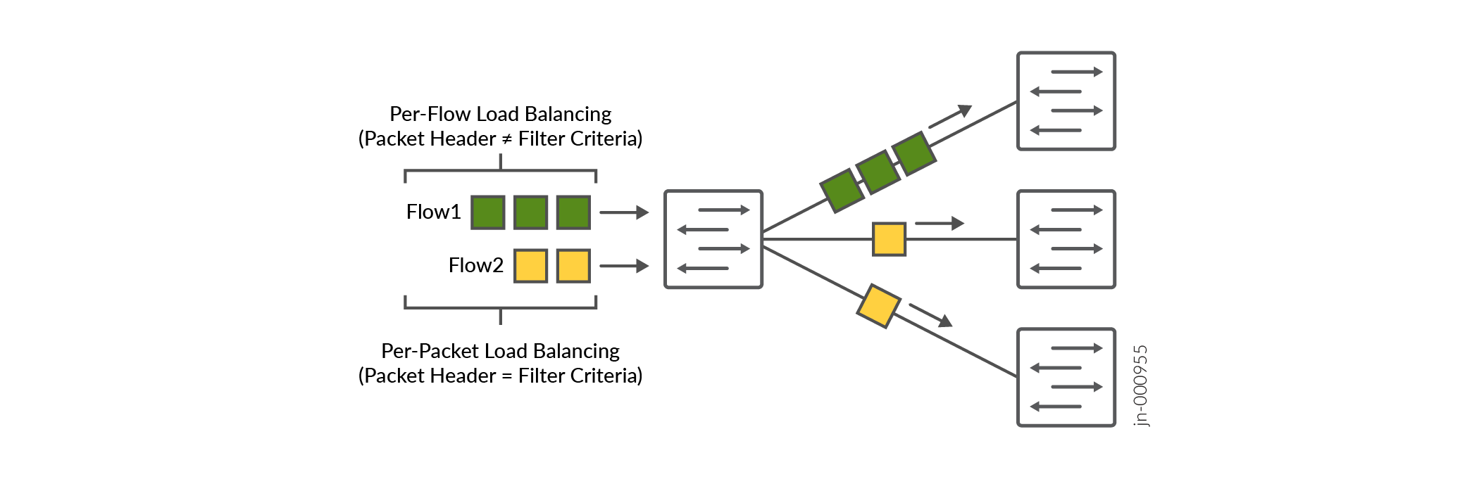
You can enable load balancing in two ways: per flow or per packet. Per-flow load balancing has been the most widely used because it handles the largest number of packets at a time. The device classifies packets that have the same 5-tuple packet headers as a single flow. The device gives all packets in the flow the same load balancing treatment. Flow-based load balancing works well for general TCP and UDP traffic because the traffic utilizes all links fairly equally. However, per-packet load balancing can reorder some packets, which can impact performance.
Many AI clusters connect the application to the network through smart network interface cards (SmartNICs) that can handle out-of-order packets. To improve performance, enable per-packet DLB on your network. Then enable DLB for only those endpoint servers that are capable of handling out-of-order packets. Your device looks at the RDMA operation codes (opcodes) in the BTH+ headers of these packets in real time. Using any firewall filter match condition, you can selectively enable or disable DLB based on these opcodes. Other flows continue to use default hash-based load balancing, also known as SLB.
Configuration
- Configuration Overview
- Topology
- Disable DLB Globally and Selectively Enable DLB
- Enable DLB Globally and Selectively Disable DLB
Configuration Overview
You can selectively enable DLB in two ways: disable DLB by default and selectively enable DLB on certain flows, or enable DLB globally and selectively disable DLB. In either case, you'll need to first configure DLB in per-packet mode. Per-packet is the DLB mode used wherever DLB is enabled. You cannot configure DLB in per-flow and per-packet mode on the same device at the same time.
This feature is compatible with flowlet mode. You can optionally enable this feature when DLB is configured in flowlet mode.
Topology
In the topology shown in Figure 2, DLB is disabled by default. We have enabled DLB selectively on Flow2 in per-packet mode. Table 1 summarizes the load balancing configuration on the two flows shown and the results of the load balancing applied on the flows:
|
Flow |
DLB Enabled? |
Result |
|---|---|---|
|
Flow1 |
No |
The device uses the default load balancing configuration, which is per-flow mode. The flow is directed to a single device. |
|
Flow2 |
Yes |
The device uses the DLB configuration, which is per-packet mode. The device splits this flow into packets. DLB assigns each packet to a path that is based on the RDMA opcode in the packet header and the corresponding filter. |
Disable DLB Globally and Selectively Enable DLB
In cases where very few packets will require DLB, you can disable DLB at the global level and selectively enable it per flow.
Enable DLB Globally and Selectively Disable DLB
In cases where most packets will benefit from DLB, enable DLB at the global level for all packets and selectively disable it per packet.
Example: Selectively Enable DLB with a Firewall Filter Match Condition
One of the benefits of selective DLB is that you can customize load balancing based on any firewall filter match condition. This example shows how to enable DLB based on a firewall filter that matches with RDMA queue pairs. Use this example to enable per-packet DLB only for those flows terminating on a network interface card (NIC) that supports packet reordering.
In a network that uses RoCEv2 for application traffic transport, an RDMA connection sends traffic on a send queue and receives traffic on a receive queue. These queues form the RDMA connection. Together, the send queue and receive queue are referred to as a queue pair. Each queue pair has an identifiable prefix. In this example, we use queue pair prefixes to control when DLB is enabled.
This example is configured on a QFX5240-64QD switch.
Customize Egress Port Link Quality Metrics for DLB
Overview
Dynamic load balancing (DLB) selects an optimal link based on the quality of the link so that traffic flows are evenly distributed across your network. You (the network administrator) can customize the way DLB assigns quality metrics of egress ports so that DLB selects the optimal link.
DLB assigns each egress port that is part of equal-cost multipath (ECMP) to a quality band. Quality bands are numbered from 0 through 7, where 0 is the lowest quality and 7 is the highest quality. DLB tracks two metrics on each of the ports, and it uses these metrics to compute the link quality:
-
Port load metric: The amount of traffic recently transmitted over each ECMP link, measured in bytes.
-
Port queue metric: The amount of traffic enqueued on each ECMP link for transmission, measured in number of cells.
Based on the member port load and queue size, DLB assigns one of the quality bands to the member port. The port-to-quality band mapping changes based on the instantaneous port load and queue size metrics.
By default, DLB weighs the port load metric and port queue metric equally when
evaluating link quality. You can configure DLB to base the link quality more heavily
on the port load than the port queue, or vice versa. Configure the amount of weight
DLB places on the port load using the rate-weightage statement at
the [edit forwarding-options enhanced-hash-key ecmp-dlb
egress-quantization] hierarchy level. DLB assigns the remaining weight
percentage to the port queue. For example, if you configure the
rate-weightage value to be 80, DLB places 80% weight on the
port load and 20% weight on the port queue when evaluating the quality of a
link.
You can also configure port load thresholds that determine the upper and lower
quality bands. The thresholds are percentages of the total port load that you
configure using the min and max options. DLB
assigns any egress port with a port load falling below this minimum to the highest
quality band (7). Any port load larger than the maximum threshold falls into the
lowest quality band (0). DLB divides the remaining port load quantities among
quality bands 1 through 6.
For example, if you configure the minimum to be 10 and the maximum to be 70, DLB assigns any egress port with a port load that takes up less than 10 percent (%) of the total port load to quality band 7. DLB assigns any egress port with a port load taking up more than 70% of the total port load to quality band 0. DLB then assigns egress ports with port loads taking up 10% through 70% of the total port load to quality bands 1 through 6.
Use Feature Explorer to confirm platform and release support for specific features.
Benefits
-
Optimized load balancing based on a port's load size and queues.
-
Link quality parameters that suit your network needs.
-
Flexible port assignment to quality bands based on real-time metrics.
Configuration
Configure the egress port quality metric.
Configure Flowset Table Size in DLB Flowlet Mode
Overview
Dynamic load balancing (DLB) is a load balancing technique that selects an optimal egress link based on link quality so that traffic flows are evenly distributed. You (the network administrator) can configure DLB in flowlet mode.
In flowlet mode, DLB tracks the flows by recording the last seen timestamp and the egress interface that DLB selected based on the optimal link quality. DLB records this information in the flowset table allocated to each ECMP group. The DLB algorithm maintains a given flow on a particular link until the last seen timestamp exceeds the inactivity timer. When the inactivity timer expires for a particular flow, DLB rechecks whether that link is still optimal for that flow. If the link is no longer optimal, DLB selects a new egress link and updates the flowset table with the new link and the last known timestamp of the flow. If the link continues to be optimal, the flowset table continues to use the same egress link.
You (the network administrator) can increase the flowset table size to change the distribution of the flowset table entries among the ECMP groups. The more entries an ECMP group has in the flowset table, the more flows the ECMP group can accommodate. In environments such as AI-ML data centers that must handle large numbers of flows, it is particularly useful for DLB to use a larger flowset table size. When each ECMP group can accommodate a large number of flows, DLB achieves better flow distribution across the ECMP member links.
The flowset table holds 32,768 total entries, and these entries are divided equally among the DLB ECMP groups. The flowset table size for each ECMP group ranges from 256 through 32,768. Use the following formula to calculate the number of ECMP groups:
32,768/(flowset size) = Number of ECMP groups
By default, the flowset size is 256 entries, so by default there are 128 ECMP groups.
Use Feature Explorer to confirm platform and release support for specific features.
Benefits
-
Improve load distribution over egress links.
-
Group flows to minimize how many calculations DLB has to make for each flow.
-
Customize flowset table entry allocation for maximum efficiency.
-
Increase the efficiency of flowlet mode.
Configuration
Be aware of the following when configuring the flowset table size:
-
When you change the flowset size, the scale of ECMP DLB groups also changes. Allocating a flowset table size greater than 256 reduces the number of DLB-capable ECMP groups.
-
When you commit this configuration, traffic can drop during the configuration change.
-
DLB is not supported when a link aggregation group (LAG) is one of the egress members of ECMP.
-
Only underlay fabrics support DLB.
-
QFX5240 switch ports with a speed less than 50 Gbps do not support DLB.
Reactive Path Rebalancing
Overview
Dynamic load balancing (DLB) is an important tool for handling the large data flows (also known as elephant flows) inherent in AI-ML data center fabrics. Reactive path rebalancing is an enhancement to existing DLB features.
In the flowlet mode of DLB, you (the network administrator) configure an inactivity interval. The traffic uses the assigned outgoing (egress) interface until the flow pauses for longer than the inactivity timer. If the outgoing link quality deteriorates gradually, the pause within the flow might not exceed the configured inactivity timer. In this case, classic flowlet mode does not reassign the traffic to a different link, so the traffic cannot utilize a better-quality link. Reactive path rebalancing addresses this limitation by enabling the user to move the traffic to a better-quality link even when flowlet mode is enabled.
The device assigns a quality band to each equal-cost multipath (ECMP) egress member link that is based on the traffic flowing through the link. The quality band depends on the port load and the queue buffer. The port load is the number of egress bytes transmitted. The queue buffer is the number of bytes waiting to be transmitted from the egress port. You can customize these attributes based on the traffic pattern flowing through the ECMP.
Use Feature Explorer to confirm platform and release support for specific features.
Benefits
-
Scalable solution to link degradation
-
Optimal use of bandwidth for large data flows
-
Avoidance of load balancing inefficiencies due to long-lived flows
Configuration
Configuration Overview
Quality bands are numbered from 0 through 7, where 0 is the lowest quality and 7 is the highest quality. Based on the member port load and queue size, DLB assigns a quality band value to the member port. The port-to-quality band mapping changes based on instantaneous port load and queue size.
When both of the following conditions are met, reactive path rebalancing reassigns a flow to a higher-quality member link:
-
A better-quality member link is available whose quality band is equal to or greater than the current member's quality band plus the configured reassignment quality delta value. The quality delta is the difference between the two quality bands. Configure the quality delta value using the
quality-deltastatement. -
The packet random value that the system generates is lower than the reassignment probability threshold value. Configure the probability threshold value using the
prob-thresholdstatement.
Be aware of the following when using this feature:
-
Reactive path rebalancing is a global configuration and applies to all ECMP DLB configurations in the system.
-
You can configure egress quantization in addition to reactive path rebalancing to control the flow reassignment.
-
Packet reordering can occur when the flow moves from one port to another. Configuring reactive path rebalancing can cause momentary out-of-order issues when the flow is reassigned to the new link.
Topology
In this topology, the device has three ingress ports and two egress ports. Two of the ingress streams are Layer 2 (L2) traffic and one is Layer 3 (L3) traffic. The figure shows the table entries forwarding the traffic to each of the egress ports. All the ingress and egress ports are of the same speed.
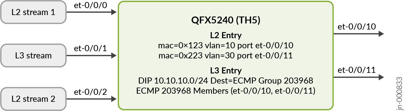
In this topology, reactive path rebalancing works as follows:
Quality delta of 2 is configured.
L2 stream 1 (
mac 0x123) enters ingress port et-0/0/0 with a rate of 10 percent. It exits through et-0/0/10. The egress link utilization of et-0/0/10 is 10 percent and the quality band value is 6.The L3 stream enters port et-0/0/1 with a rate of 50 percent. It exits through et-0/0/11 and selects the optimal link from the ECMP member list. The egress link utilization of et-0/0/11 is 50 percent with a quality band value of 5.
L2 stream 2 (
mac 0x223) enters port et-0/0/2 with a rate of 40 percent. It also exits through et-0/0/11. This further degrades the et-0/0/11 link quality band value to 4. Now the difference in the quality band values of both ECMP member links is 2.The reactive path balancing algorithm now becomes operational because the difference in quality band values for ports et-0/0/10 and et-0/0/11 is equal to or higher than the configured quality delta of 2. The algorithm moves the L3 stream from et-0/0/11 to a better-quality member link, which in this case is et-0/0/10.
After the L3 steam moves to et-0/0/10, the et-0/0/10 link utilization increases to 60 percent with a decrease in quality band value to 5. L2 stream 2 continues to exit through et-0/0/11. The et-0/0/11 link utilization remains at 40 percent with an increase in quality band value to 5.
Configure Reactive Path Rebalancing
Change History Table
Feature support is determined by the platform and release you are using. Use Feature Explorer to determine if a feature is supported on your platform.