BGP PIC for Layer 3 VPNs
Configuring BGP PIC Edge for MPLS Layer 3 VPNs
In an MPLS VPN Layer 3 environment, it is common for customers to multihome their networks to provide link redundancy. Although the interior gateway protocol (IGP) can provide fast convergence, in certain instances, the time to resolve a link failure and provide an alternate route can be time consuming. For example, a provider edge (PE) router might be configured with 200,000 or more IP prefixes, and a PE router failure could affect many of those prefixes.
BGP Prefix-Independent Convergence (PIC) Edge allows you to install a Layer 3 VPN route in the forwarding table as an alternate path, enabling fast failover when a PE router fails or you lose connectivity to a PE router. This already installed path is used until global convergence through the IGP is resolved. Using the alternative VPN route for forwarding until global convergence is complete reduces traffic loss.
BGP PIC Edge supports multiprotocol BGP IPv4 or IPv6 VPN network layer reachability information (NLRI) resolved using any of these IGP protocols:
-
OSPF
-
IS-IS
-
LDP
-
RSVP
BGP PIC Edge does not support multicast traffic.
Before you begin:
Configure LDP or RSVP.
Configure an IGP: either OSPF or IS-IS.
Configure a Layer 3 VPN.
Configure multiprotocol BGP for either an IPv4 VPN or an IPv6 VPN.
To configure BGP PIC Edge in an MPLS Layer 3 VPN:
Platform Specific BGP PIC Edge Behavior
Use Feature Explorer to confirm platform and release support for specific features.
Use the following table to review platform-specific behaviors for your platform
|
Platform |
Difference |
|---|---|
|
MX Series |
On MX Series 5G Universal Routing Platforms with Modular Port Concentrators (MPCs), we strongly recommend that you enable enhanced IP network services. To enable enhanced IP network services: [edit chassis] user@host# set network-services enhanced-ip |
Example: Configuring BGP PIC Edge for MPLS Layer 3 VPNs
This example shows how to configure BGP prefix-independent convergence (PIC) edge, which allows you to install a Layer 3 VPN route in the forwarding table as an alternate path. This enables fast failover when a provider edge (PE) router fails or you lose connectivity to a PE router. This already installed path is used until global convergence through the interior gateway protocol (IGP) is resolved. Using the alternative VPN route for forwarding until global convergence is complete reduces traffic loss.
Requirements
No special configuration beyond device initialization is required before configuring this example.
This example uses the following hardware and software components:
-
The MX Series 5G Universal Routing Platforms.
-
Junos OS Release 13.2 or later on the device with BGP PIC edge configured.
Overview
In an MPLS VPN Layer 3 environment, it is common for customers to multihome their networks to provide link redundancy. Although the interior gateway protocol (IGP) can provide fast convergence, in certain instances, the time to resolve a link failure and provide an alternate route can be time consuming. For example, a provider edge (PE) router might be configured with 200,000 or more IP prefixes, and a PE router failure could affect many of those prefixes.
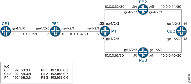
This example shows two customer edge (CE) routers, Device CE1 and Device CE2. Devices PE1, PE2, and PE3 are PE routers. Device P1 is a provider core router. Only Device PE1 has BGP PIC edge configured. The example uses the P1-PE2 link (P-PE) link to simulate the loss of a section of the network.
For testing, the address 172.16.1.5/24 is added as a loopback interface address on Device CE2. The address is announced to Device PE2 and Device PE3 and is relayed by way of internal BGP (IBGP) IBGP to Device PE1. On Device PE1, there are two paths to the 172.16.1.5/24 network. These are the primary and a backup path.
Topology
Figure 1 shows the sample network.
CLI Quick Configuration shows the configuration for all of the devices in Figure 1.
The section Step-by-Step Procedure describes the steps on Device PE1.
Configuration
CLI Quick Configuration
To quickly configure
this example, copy the following commands, paste them into a text
file, remove any line breaks, change any details necessary to match
your network configuration, and then copy and paste the commands into
the CLI at the [edit] hierarchy level.
Device CE1
set interfaces ge-1/2/0 unit 0 family inet address 10.0.0.1/30
set interfaces lo0 unit 0 family inet address 192.168.0.1/32
set protocols bgp group ebgp type external
set protocols bgp group ebgp export send-direct
set protocols bgp group ebgp neighbor 10.0.0.2
set policy-options policy-statement send-direct from protocol direct
set policy-options policy-statement send-direct then accept
set routing-options autonomous-system 101
Device CE2
set interfaces ge-1/2/4 unit 0 family inet address 10.0.0.42/30
set interfaces ge-1/2/3 unit 0 family inet address 10.0.0.46/30
set interfaces lo0 unit 0 family inet address 192.168.0.8/32
set interfaces lo0 unit 0 family inet address 172.16.1.5/24
set protocols bgp group ebgp type external
set protocols bgp group ebgp export send-direct
set protocols bgp group ebgp neighbor 10.0.0.45
set protocols bgp group ebgp neighbor 10.0.0.41
set policy-options policy-statement send-direct from protocol direct
set policy-options policy-statement send-direct then accept
set routing-options autonomous-system 102
Device P1
set interfaces ge-1/2/1 unit 0 family inet address 10.0.0.5/30
set interfaces ge-1/2/1 unit 0 family mpls
set interfaces ge-1/2/5 unit 0 family inet address 10.0.0.17/30
set interfaces ge-1/2/5 unit 0 family mpls
set interfaces ge-1/2/2 unit 0 family inet address 10.0.0.33/30
set interfaces ge-1/2/2 unit 0 family mpls
set interfaces lo0 unit 0 family inet address 192.168.0.3/32
set protocols mpls interface ge-1/2/1.0
set protocols mpls interface ge-1/2/5.0
set protocols mpls interface ge-1/2/2.0
set protocols ospf area 0.0.0.0 interface ge-1/2/1.0
set protocols ospf area 0.0.0.0 interface ge-1/2/5.0
set protocols ospf area 0.0.0.0 interface ge-1/2/2.0
set protocols ospf area 0.0.0.0 interface lo0.0 passive
set protocols ldp interface ge-1/2/1.0
set protocols ldp interface ge-1/2/5.0
set protocols ldp interface ge-1/2/2.0
set protocols ldp interface lo0.0
set routing-options autonomous-system 100
Device PE1
set interfaces ge-1/2/0 unit 0 family inet address 10.0.0.2/30
set interfaces ge-1/2/1 unit 0 family inet address 10.0.0.6/30
set interfaces ge-1/2/1 unit 0 family mpls
set interfaces lo0 unit 0 family inet address 192.168.0.2/32
set protocols mpls interface ge-1/2/1.0
set protocols bgp group ibgp type internal
set protocols bgp group ibgp local-address 192.168.0.2
set protocols bgp group ibgp family inet unicast
set protocols bgp group ibgp family inet-vpn unicast
set protocols bgp group ibgp export nhs
set protocols bgp group ibgp neighbor 192.168.0.7
set protocols bgp group ibgp neighbor 192.168.0.6
set protocols ospf area 0.0.0.0 interface ge-1/2/1.0
set protocols ospf area 0.0.0.0 interface lo0.0 passive
set protocols ldp interface ge-1/2/1.0
set protocols ldp interface lo0.0
set policy-options policy-statement lb then load-balance per-packet
set policy-options policy-statement nhs then next-hop self
set routing-instances customer1 instance-type vrf
set routing-instances customer1 interface ge-1/2/0.0
set routing-instances customer1 route-distinguisher 100:1
set routing-instances customer1 vrf-target target:100:1
set routing-instances customer1 routing-options protect core
set routing-instances customer1 protocols bgp group ebgp type external
set routing-instances customer1 protocols bgp group ebgp neighbor 10.0.0.1
set routing-options router-id 192.168.0.2
set routing-options autonomous-system 100
set routing-options forwarding-table export lb
Device PE2
set interfaces ge-1/2/2 unit 0 family inet address 10.0.0.34/30
set interfaces ge-1/2/2 unit 0 family mpls
set interfaces ge-1/2/3 unit 0 family inet address 10.0.0.45/30
set interfaces lo0 unit 0 family inet address 192.168.0.7/32
set protocols mpls interface ge-1/2/2.0
set protocols bgp group ibgp type internal
set protocols bgp group ibgp local-address 192.168.0.7
set protocols bgp group ibgp family inet unicast
set protocols bgp group ibgp family inet-vpn unicast
set protocols bgp group ibgp export nhs
set protocols bgp group ibgp neighbor 192.168.0.2
set protocols bgp group ibgp neighbor 192.168.0.6
set protocols ospf area 0.0.0.0 interface ge-1/2/2.0
set protocols ospf area 0.0.0.0 interface lo0.0 passive
set protocols ldp interface ge-1/2/2.0
set protocols ldp interface lo0.0
set routing-instances customer1 instance-type vrf
set routing-instances customer1 interface ge-1/2/3.0
set routing-instances customer1 route-distinguisher 100:1
set routing-instances customer1 vrf-target target:100:1
set routing-instances customer1 protocols bgp group ebgp type external
set routing-instances customer1 protocols bgp group ebgp neighbor 10.0.0.46
set routing-options autonomous-system 100
Device PE3
set interfaces ge-1/2/5 unit 0 family inet address 10.0.0.18/30
set interfaces ge-1/2/5 unit 0 family mpls
set interfaces ge-1/2/4 unit 0 family inet address 10.0.0.41/30
set interfaces ge-1/2/4 unit 0 family mpls
set interfaces lo0 unit 0 family inet address 192.168.0.6/32
set protocols mpls interface ge-1/2/5.0
set protocols mpls interface ge-1/2/4.0
set protocols bgp group ibgp type internal
set protocols bgp group ibgp local-address 192.168.0.6
set protocols bgp group ibgp family inet unicast
set protocols bgp group ibgp family inet-vpn unicast
set protocols bgp group ibgp export nhs
set protocols bgp group ibgp neighbor 192.168.0.7
set protocols bgp group ibgp neighbor 192.168.0.2
set protocols ospf area 0.0.0.0 interface ge-1/2/5.0
set protocols ospf area 0.0.0.0 interface lo0.0 passive
set protocols ldp interface ge-1/2/5.0
set protocols ldp interface lo0.0
set routing-instances customer1 instance-type vrf
set routing-instances customer1 interface ge-1/2/4.0
set routing-instances customer1 route-distinguisher 100:1
set routing-instances customer1 vrf-target target:100:1
set routing-instances customer1 protocols bgp group ebgp type external
set routing-instances customer1 protocols bgp group ebgp neighbor 10.0.0.42
set routing-options autonomous-system 100
Procedure
Step-by-Step Procedure
The following example requires that you navigate various levels in the configuration hierarchy. For information about navigating the CLI, see Using the CLI Editor in Configuration Mode in the CLI User Guide.
To configure Device R1:
-
Configure the device interfaces.
[edit interfaces]
user@PE1# set ge-1/2/0 unit 0 family inet address 10.0.0.2/30
user@PE1# set ge-1/2/1 unit 0 family inet address 10.0.0.6/30
user@PE1# set ge-1/2/1 unit 0 family mpls
user@PE1# set lo0 unit 0 family inet address 192.168.0.2/32
-
Configure MPLS and LDP on the core-facing interfaces.
[edit protocols]
user@PE1# set mpls interface ge-1/2/1.0
user@PE1# set ldp interface ge-1/2/1.0
user@PE1# set ldp interface lo0.0
-
Configure an IGP on the core-facing interfaces.
[edit protocols ospf area 0.0.0.0]
user@PE1# set interface ge-1/2/1.0
user@PE1# set interface lo0.0 passive
-
Configure IBGP connections with the other PE devices.
[edit protocols bgp group ibgp]
user@PE1# set type internal
user@PE1# set local-address 192.168.0.2
user@PE1# set family inet unicast
user@PE1# set family inet-vpn unicast
user@PE1# set export nhs
user@PE1# set neighbor 192.168.0.7
user@PE1# set neighbor 192.168.0.6
-
Configure the load-balancing policy.
[edit policy-options policy-statement lb]
user@PE1# set then load-balance per-packet
-
(Optional) Configure a next-hop self policy.
[edit policy-options policy-statement nhs]
user@PE1# set then next-hop self
-
Configure the routing-instance to create the CE-PE EBGP connection.
[edit routing-instances customer1]
user@PE1# set instance-type vrf
user@PE1# set interface ge-1/2/0.0
user@PE1# set route-distinguisher 100:1
user@PE1# set vrf-target target:100:1
user@PE1# set protocols bgp group ebgp type external
user@PE1# set protocols bgp group ebgp neighbor 10.0.0.1
-
Enable the BGP PIC edge feature.
[edit routing-instances customer1]
user@PE1# set  routing-options protect core
-
Apply the load-balancing policy.
[edit routing-options forwarding-table]
user@PE1# set export lb
-
Assign the router ID and autonomous system (AS) number.
[edit routing-options]
user@PE1# set router-id 192.168.0.2
user@PE1# set autonomous-system 100
Results
From configuration mode, confirm your configuration
by entering the show interfaces, show protocols, show policy-options, show routing-instances, and show routing-options commands. If the output does
not display the intended configuration, repeat the instructions in
this example to correct the configuration.
user@PE1# show interfaces
ge-1/2/0 {
    unit 0 {
        family inet {
            address 10.0.0.2/30;
        }
    }
}
ge-1/2/1 {
    unit 0 {
        family inet {
            address 10.0.0.6/30;
        }
        family mpls;
    }
}
lo0 {
    unit 0 {
        family inet {
            address 192.168.0.2/32;
        }
    }
}
user@PE1# show protocols
mpls {
    interface ge-1/2/1.0;
}
bgp {
    group ibgp {
        type internal;
        local-address 192.168.0.2;
        family inet {
            unicast;
        }
        family inet-vpn {
            unicast;
        }
        export nhs;
        neighbor 192.168.0.7;
        neighbor 192.168.0.6;
    }
}
ospf {
    area 0.0.0.0 {
        interface ge-1/2/1.0;
        interface lo0.0 {
            passive;
        }
    }
}
ldp {
    interface ge-1/2/1.0;
    interface lo0.0;
}
user@PE1# show policy-options
policy-statement lb {
    then {
        load-balance per-packet;
    }
}
policy-statement nhs {
    then {
        next-hop self;
    }
}
user@PE1# show routing-instances
customer1 {
    instance-type vrf;
    interface ge-1/2/0.0;
    route-distinguisher 100:1;
    vrf-target target:100:1;
    routing-options {
        protect core;
    }
    protocols {
        bgp {
            group ebgp {
                type external;
                peer-as 101;
                neighbor 10.0.0.1;
            }
        }
    }
}
user@PE1# show routing-options
router-id 192.168.0.2;
autonomous-system 100;
forwarding-table {
    export lb;
}
If you are done configuring the device, enter commit from configuration mode.
Verification
Confirm that the configuration is working properly.
Displaying Extensive Route Information
Purpose
Confirm that BGP PIC Edge is working.
Action
From Device PE1, run the show route extensive table
customer1.inet.0 172.16.1/24 command.
user@PE1> show route extensive table customer1.inet.0 172.16.1/24

customer1.inet.0: 7 destinations, 12 routes (7 active, 0 holddown, 0 hidden)
172.16.1.0/24 (3 entries, 2 announced)
        State: <CalcForwarding>
TSI:
KRT in-kernel 172.16.1.0/24 -> {indirect(262146), indirect(262142)}
Page 0 idx 0, (group ebgp type External) Type 1 val 0x950a62c (adv_entry)
   Advertised metrics:
     Nexthop: Self
     AS path: [100] 102 I
     Communities: target:100:1
Path 172.16.1.0 from 192.168.0.6 Vector len 4.  Val: 0
        @BGP    Preference: 170/-101
                Route Distinguisher: 100:1
                Next hop type: Indirect
                Address: 0x9514a74
                Next-hop reference count: 7
                Source: 192.168.0.6
                Next hop type: Router, Next hop index: 990
                Next hop: 10.0.0.5 via ge-1/2/1.0, selected
                Label operation: Push 299824, Push 299856(top)
                Label TTL action: prop-ttl, prop-ttl(top)
                Load balance label: Label 299824: None; Label 299856: None;
                Session Id: 0x280002
                Protocol next hop: 192.168.0.6
                Label operation: Push 299824
                Label TTL action: prop-ttl
                Load balance label: Label 299824: None;
                Indirect next hop: 0x96bc104 262146 INH Session ID: 0x280006
                State: <Secondary Active Int Ext ProtectionPath ProtectionCand>
                Local AS:   100 Peer AS:   100
                Age: 1:38:13    Metric2: 1
                Validation State: unverified
                Task: BGP_100.192.168.0.6+45824
                Announcement bits (1): 1-BGP_RT_Background
                AS path: 102 I
                Communities: target:100:1
                Import Accepted
                VPN Label: 299824
                Localpref: 100
                Router ID: 192.168.0.6
                Primary Routing Table bgp.l3vpn.0
                Indirect next hops: 1
                        Protocol next hop: 192.168.0.6 Metric: 1
                        Label operation: Push 299824
                        Label TTL action: prop-ttl
                        Load balance label: Label 299824: None;
                        Indirect next hop: 0x96bc104 262146 INH Session ID: 0x280006
                        Indirect path forwarding next hops: 1
                                Next hop type: Router
                                Next hop: 10.0.0.5 via ge-1/2/1.0
                                Session Id: 0x280002
                        192.168.0.6/32 Originating RIB: inet.3
                          Metric: 1                       Node path count: 1
                          Forwarding nexthops: 1
                                Nexthop: 10.0.0.5 via ge-1/2/1.0
         BGP    Preference: 170/-101
                Route Distinguisher: 100:1
                Next hop type: Indirect
                Address: 0x9515570
                Next-hop reference count: 7
                Source: 192.168.0.7
                Next hop type: Router, Next hop index: 933
                Next hop: 10.0.0.5 via ge-1/2/1.0, selected
                Label operation: Push 299856, Push 299872(top)
                Label TTL action: prop-ttl, prop-ttl(top)
                Load balance label: Label 299856: None; Label 299872: None;
                Session Id: 0x280002
                Protocol next hop: 192.168.0.7
                Label operation: Push 299856
                Label TTL action: prop-ttl
                Load balance label: Label 299856: None;
                Indirect next hop: 0x96bc000 262142 INH Session ID: 0x280005
                State: <Secondary NotBest Int Ext ProtectionPath ProtectionCand>
                Inactive reason: Not Best in its group - Router ID
                Local AS:   100 Peer AS:   100
                Age: 1:38:13    Metric2: 1
                Validation State: unverified
                Task: BGP_100.192.168.0.7+10985
                AS path: 102 I
                Communities: target:100:1
                Import Accepted
                VPN Label: 299856
                Localpref: 100
                Router ID: 192.168.0.7
                Primary Routing Table bgp.l3vpn.0
                Indirect next hops: 1
                        Protocol next hop: 192.168.0.7 Metric: 1
                        Label operation: Push 299856
                        Label TTL action: prop-ttl
                        Load balance label: Label 299856: None;
                        Indirect next hop: 0x96bc000 262142 INH Session ID: 0x280005
                        Indirect path forwarding next hops: 1
                                Next hop type: Router
                                Next hop: 10.0.0.5 via ge-1/2/1.0
                                Session Id: 0x280002
                        192.168.0.7/32 Originating RIB: inet.3
                          Metric: 1                       Node path count: 1
                          Forwarding nexthops: 1
                                Nexthop: 10.0.0.5 via ge-1/2/1.0
        #Multipath Preference: 255
                Next hop type: Indirect
                Address: 0x9578010
                Next-hop reference count: 4
                Next hop type: Router, Next hop index: 990
                Next hop: 10.0.0.5 via ge-1/2/1.0, selected
                Label operation: Push 299824, Push 299856(top)
                Label TTL action: prop-ttl, prop-ttl(top)
                Load balance label: Label 299824: None; Label 299856: None;
                Session Id: 0x280002
                Next hop type: Router, Next hop index: 933
                Next hop: 10.0.0.5 via ge-1/2/1.0
                Label operation: Push 299856, Push 299872(top)
                Label TTL action: prop-ttl, prop-ttl(top)
                Load balance label: Label 299856: None; Label 299872: None;
                Session Id: 0x280002
                Protocol next hop: 192.168.0.6
                Label operation: Push 299824
                Label TTL action: prop-ttl
                Load balance label: Label 299824: None;
                Indirect next hop: 0x96bc104 262146 INH Session ID: 0x280006 Weight 0x1
                Protocol next hop: 192.168.0.7
                Label operation: Push 299856
                Label TTL action: prop-ttl
                Load balance label: Label 299856: None;
                Indirect next hop: 0x96bc000 262142 INH Session ID: 0x280005 Weight 0x4000
                State: <ForwardingOnly Int Ext>
                Inactive reason: Forwarding use only
                Age: 1:38:13    Metric2: 1
                Validation State: unverified
                Task: RT
                Announcement bits (1): 0-KRT
                AS path: 102 I
                Communities: target:100:1
Meaning
The Indirect next hop output lines that contain weight follow next hops that the software can use to repair paths where a link failure occurs.
The next-hop weight has one of the following values:
-
0x1 indicates active next hops.
-
0x4000 indicates passive next hops.
Displaying the Forwarding Table
Purpose
Check the forwarding and kernel routing-table state
by using show route forwarding-table.
Action
From Device PE1, run the show route forwarding-table
table customer1 destination 172.16.1.0/24 command.
user@PE1> show route forwarding-table table customer1 destination 172.16.1.0/24

Routing table: customer1.inet
Internet:
Destination        Type RtRef Next hop           Type Index    NhRef Netif
172.16.1.0/24      user     0                    ulst   262147     2
                                                 indr   262146     3
                              10.0.0.5          Push 299824, Push 299856(top)      990     2 ge-1/2/1.0
                                                 indr   262144     3
                              10.0.0.5          Push 300080, Push 299920(top)     1000     2 ge-1/2/1.0
Meaning
in addition to the forwarding and kernel routing-table state, this command shows the unilist index (262147) used by the Packet Forwarding Engine.
Displaying the OSPF Routes
Purpose
Show the OSPF route state.
Action
From Device PE1, run the
show (ospf | ospf3) route detail command.
user@PE1> show ospf route detail

betsy@tp0:PE1> show ospf route detail
Topology default Route Table:

Prefix             Path  Route      NH       Metric NextHop       Nexthop
                   Type  Type       Type            Interface     Address/LSP
192.168.0.3        Intra Router     IP            1 ge-1/2/1.0    10.0.0.5
  area 0.0.0.0, origin 192.168.0.3, optional-capability 0x0
192.168.0.6        Intra Router     IP            2 ge-1/2/1.0    10.0.0.5
  area 0.0.0.0, origin 192.168.0.6, optional-capability 0x0
192.168.0.7        Intra Router     IP            2 ge-1/2/1.0    10.0.0.5
  area 0.0.0.0, origin 192.168.0.7, optional-capability 0x0
10.0.0.4/30        Intra Network    IP            1 ge-1/2/1.0
  area 0.0.0.0, origin 192.168.0.3, priority low
10.0.0.16/30       Intra Network    IP            2 ge-1/2/1.0    10.0.0.5
  area 0.0.0.0, origin 192.168.0.6, priority medium
10.0.0.32/30       Intra Network    IP            2 ge-1/2/1.0    10.0.0.5
  area 0.0.0.0, origin 192.168.0.7, priority medium
192.168.0.2/32     Intra Network    IP            0 lo0.0
  area 0.0.0.0, origin 192.168.0.2, priority low
192.168.0.3/32     Intra Network    IP            1 ge-1/2/1.0    10.0.0.5
  area 0.0.0.0, origin 192.168.0.3, priority medium
192.168.0.6/32     Intra Network    IP            2 ge-1/2/1.0    10.0.0.5
  area 0.0.0.0, origin 192.168.0.6, priority medium
  session-id: 2621446, version: 1
192.168.0.7/32     Intra Network    IP            2 ge-1/2/1.0    10.0.0.5
  area 0.0.0.0, origin 192.168.0.7, priority medium
  session-id: 2621450, version: 1
Meaning
The output shows the tracked session IDs for the loopback interface addresses on Devices PE2 and PE3.