ON THIS PAGE
Redundant Virtual Tunnels Providing Resiliency in Delivering Multicast Traffic Overview
Configuring Redundant Virtual Tunnels to Provide Resiliency in Delivering Multicast Traffic
Example: Configuring Redundant Virtual Tunnels to Provide Resiliency in Delivering Multicast Traffic
Understanding Redundant Virtual Tunnel Interfaces in MBGP MVPNs
Example: Configuring Redundant Virtual Tunnel Interfaces in MBGP MVPNs
Resiliency in Multicast L3 VPNs with Redundant Virtual Tunnels
Redundant Virtual Tunnels Providing Resiliency in Delivering Multicast Traffic Overview
In multicast Layer 3 VPNs, virtual tunnel (VT) interfaces are needed to facilitate virtual routing and forwarding (VRF) table lookup based on MPLS labels.
Junos OS supports redundant VTs at the Packet Forwarding Engine level to improve resiliency in delivering multicast traffic.
Redundant VTs are supported only on MX Series routers with MPCs.
To create redundant VTs at the Packet Forwarding Engine level, you add member VTs (vt- interfaces) to a parent VT (rvt interface).
Configuring redundant VT interfaces on MX Series routers with MPCs has the following characteristics:
When creating a redundant VT, you can add unconfigured VTs as members of the redundant VT. You configure the redundant VT the same way you configure a regular VT, and the member VTs inherit the configuration of the parent redundant VT.
When a VT with an existing configuration joins a redundant VT, you must configure the redundant VT with the settings from the existing configuration.
You can create up to 16 redundant VTs.
You can add up to 32 VTs as members of the redundant VTs.
Note:The actual number of VTs you can create is determined by the type of chassis and the number of line cards you have.
When you add more than two VTs to a redundant VT, the members are in active mode by default, and traffic through the redundant VT is load balanced across all members of the redundant VT.
When you add only two members, you can configure the members in one of two ways:
Both members in active mode
One member in active mode and the other in backup mode
Best Practice:To set one member to active mode and the other to backup mode, we recommend that the members be hosted on different MPCs. That way, if an MPC fails, it does not bring down the entire rvt interface.
Class of service and firewall configurations involving VT interfaces work the same on redundant VT interfaces.
Redundant VTs help to provide resiliency and improve uptime
in your network when delivering multicast traffic. When enhanced-ip is enabled at the [edit chassis network-services] hierarchy
level, failure of a VT that is a member of a redundant VT can typically
be detected and fail over to another member VT provided within 50
milliseconds.
Configuring Redundant Virtual Tunnels to Provide Resiliency in Delivering Multicast Traffic
In multicast Layer 3 VPNs, virtual tunnel (VT) interfaces are needed to facilitate virtual routing and forwarding (VRF) table lookup based on MPLS labels.
Junos OS supports redundant VTs at the Packet Forwarding Engine level to improve resiliency in delivering multicast traffic.
Redundant VTs are supported only on MX Series routers with MPCs.
To create redundant VTs at the Packet Forwarding Engine level, add member VTs (vt- interfaces) to a redundant VT (rvt interface), and add that redundant VT interface to a vrf routing instance.
To configure a redundant VT:
See Also
Example: Configuring Redundant Virtual Tunnels to Provide Resiliency in Delivering Multicast Traffic
This example shows how to configure redundant virtual tunnels (VTs) in a multiprotocol BGP (MBGP) multicast VPN (MVPN). You configure a virtual loopback tunnel to facilitate virtual routing and forwarding (VRF) table lookup based on MPLS labels. Redundant VTs configured through this method provide near-immediate (less than 50 milliseconds) failover if one of the VTs fails.
Requirements
This example uses the following hardware and software components:
-
MPCs on MX Series routers
-
Junos OS Release 15.2
Overview
When a VT with an existing configuration joins a redundant VT, you must configure the redundant VT with the settings from the existing configuration.
You can add member VTs to a parent VT for redundancy.
On MX Series routers with MPCs, you can configure redundant VTs in these ways:
-
You can create up to 16 redundant VTs.
-
You can add up to 32 VTs as members of the redundant VTs.
Note:The actual number of VTs you can create is determined by the type of chassis and the number of line cards you have.
-
When you add more than two VTs to a redundant VT, the members are in active mode by default.
-
When you add only two members, you can configure the members in one of these ways:
-
Both members in active mode
-
One member in active mode and the other in backup mode
-
Topology
In this example, Device PE2 has a redundant VT interface configured in a multicast LDP routing instance. The redundant VT interface in this example contains two member VT interfaces, one in active mode and the other in backup mode.
Figure 1 shows the topology used in this example.
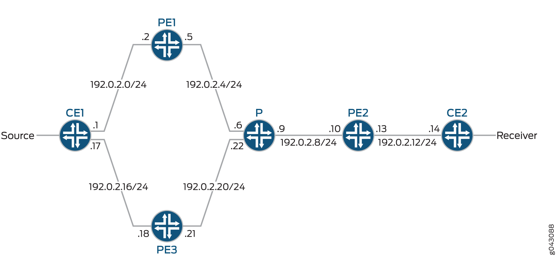
The following example shows the configuration for the customer edge (CE), provider (P), and provider edge (PE) devices in Figure 1. See Step-by-Step Procedure to configure Device PE2.
Configuration
Device P
            set chassis network-services enhanced-ip
            set interfaces ge-0/0/0 description “to PE1”
            set interfaces ge-0/0/0 unit 0 family inet address 192.0.2.6/24
            set interfaces ge-0/0/0 unit 0 family mpls
            set interfaces ge-0/0/1 description “to PE2”
            set interfaces ge-0/0/1 unit 0 family inet address 192.0.2.9/24
            set interfaces ge-0/0/1 unit 0 family mpls
            set interfaces ge-0/0/2 description “to PE3”
            set interfaces ge-0/0/2 unit 0 family inet address 192.0.2.22/24
            set interfaces ge-0/0/2 unit 0 family mpls
            set interfaces lo0 unit 0 family inet address 198.51.100.3/24
            set protocols rsvp interface all
            set protocols rsvp interface fxp0.0 disable
            set protocols mpls interface all
            set protocols mpls interface fxp0.0 disable
            set protocols bgp local-address 198.51.100.3
            set protocols bgp family inet-vpn unicast
            set protocols bgp group ibgp type internal
            set protocols bgp group ibgp local-address 198.51.100.3
            set protocols bgp group ibgp family inet any
            set protocols bgp group ibgp family inet-vpn any
            set protocols bgp group ibgp family inet-mvpn signaling
            set protocols bgp group ibgp cluster 198.51.100.3
            set protocols bgp group ibgp neighbor 198.51.100.2
            set protocols bgp group ibgp neighbor 198.51.100.4
            set protocols bgp group ibgp neighbor 198.51.100.6
            set protocols ospf traffic-engineering
            set protocols ospf area 0.0.0.0 interface lo0.0 passive
            set protocols ospf area 0.0.0.0 interface all
            set protocols ospf area 0.0.0.0 interface fxp0.0 disable
            set protocols ldp interface all
            set protocols ldp interface fxp0.0 disable
            set protocols pim interface all
            set protocols pim interface fxp0.0 disable
            set routing-options router-id 198.51.100.3
            set routing-options autonomous-system 10
Device PE2
            set chassis redundancy-group interface-type redundant-virtual-tunnel device-count 16
            set chassis fpc 1 pic 0 tunnel-services bandwidth 1g
            set chassis fpc 2 pic 0 tunnel-services bandwidth 1g
            set chassis network-services enhanced-ip
            set interfaces ge-0/0/0 description “to P”
            set interfaces ge-0/0/0 unit 0 family inet address 192.0.2.10/24
            set interfaces ge-0/0/0 unit 0 family mpls
            set interfaces ge-0/0/1 description “to CE2”
            set interfaces ge-0/0/1 unit 0 family inet address 192.0.2.13/24
            set interfaces ge-0/0/1 unit 0 family mpls
            set interfaces lo0 unit 0 family inet address 198.51.100.4/24
            set interfaces rvt0 redundancy-group member-interface vt-1/0/10 active
            set interfaces rvt0 redundancy-group member-interface vt-2/0/10 backup
            set interfaces rvt0 unit 1000 family inet
            set interfaces rvt0 unit 1000 family mpls
            set protocols rsvp interface ge-0/0/0.0
            set protocols rsvp interface fxp0.0 disable
            set protocols mpls label-switched-path PE2-to-PE1 to 198.51.100.2
            set protocols mpls label-switched-path PE2-to-PE3 to 198.51.100.6
            set protocols mpls interface ge-0/0/0.0
            set protocols mpls interface fxp0.0 disable
            set protocols bgp group ibgp type internal
            set protocols bgp group ibgp local-address 198.51.100.4
            set protocols bgp group ibgp family inet any
            set protocols bgp group ibgp family inet-vpn any
            set protocols bgp group ibgp family inet-mvpn signaling
            set protocols bgp group ibgp neighbor 198.51.100.3
            set protocols ospf traffic-engineering
            set protocols ospf area 0.0.0.0 interface lo0.0 passive
            set protocols ospf area 0.0.0.0 interface ge-0/0/0.0
            set protocols ospf area 0.0.0.0 interface fxp0.0 disable
            set protocols ldp interface all
            set protocols ldp interface fxp0.0 disable
            set protocols pim interface all
            set protocols pim interface fxp0.0 disable
            set policy-options policy-statement direct from protocol direct
            set policy-options policy-statement direct then accept
            set routing-instances vpn-1 instance-type vrf
            set routing-instances vpn-1 interface ge-0/0/1.0
            set routing-instances vpn-1 interface lo0.1
            set routing-instances vpn-1 interface rvt0.1000
            set routing-instances vpn-1 route-distinguisher 100:100
            set routing-instances vpn-1 vrf-target target:1:1
            set routing-instances vpn-1 routing-options multipath
            set routing-instances vpn-1 protocols bgp group CE2-PE2 type external
            set routing-instances vpn-1 protocols bgp group CE2-PE2 export direct
            set routing-instances vpn-1 protocols bgp group CE2-PE2 peer-as 100
            set routing-instances vpn-1 protocols bgp group CE2-PE2 neighbor 192.0.2.14 family inet unicast
            set routing-instances vpn-1 protocols ospf area 0.0.0.0 interface all
            set routing-instances vpn-1 protocols pim rp static address 192.168.0.0
            set routing-instances vpn-1 protocols pim interface all mode sparse
            set routing-instances vpn-1 protocols mvpn mvpn-mode spt-only
            set routing-instances vpn-1 protocols mvpn sender-based-rpf
            set routing-instances vpn-1 protocols mvpn hot-root-standby source-tree
            set routing-options router-id 198.51.100.4
            set routing-options autonomous-system 10
Device CE2
            set  interfaces ge-0/0/0 description “upstream to PE2”
            set  interfaces ge-0/0/0 unit 0 family inet address 192.0.2.14/24
            set  interfaces ge-0/0/0 unit 0 family mpls
            set  interfaces ge-0/0/1 description “Source-facing interface”
            set  interfaces ge-0/0/1 unit 0 family inet address 203.0.113.2/24
            set  interfaces lo0 unit 0 family inet address 198.51.100.5/24
            set  protocols bgp group CE-to-PE type external
            set  protocols bgp group CE-to-PE export direct
            set  protocols bgp group CE-to-PE peer-as 10
            set  protocols bgp group CE-to-PE local-as 100
            set  protocols bgp group CE-to-PE neighbor 192.0.2.13 family inet unicast
            set  protocols ospf area 0.0.0.0 interface lo0.0 passive
            set  protocols ospf area 0.0.0.0 interface ge-0/0/0.0
            set  protocols pim rp static address 192.168.0.0
            set  protocols pim interface all
            set  policy-options policy-statement direct from protocol direct
            set  policy-options policy-statement direct then accept
            set  routing-options router-id 198.51.100.5
            set routing-options nonstop-routing
            set routing-options autonomous-system 100
Procedure
Step-by-Step Procedure
The following example requires you to navigate various levels in the configuration hierarchy. For information about navigating the CLI, see Using the CLI Editor in Configuration Mode in the CLI User Guide.
In this section, the rvt interface is configured on Device PE2.
-
Configure the redundant virtual tunnel redundancy group and tunnel services on the chassis.
[edit chassis] user@PE2# set redundancy-group interface-type redundant-virtual-tunnel device-count 16 user@PE2# set fpc 1 pic 0 tunnel-services bandwidth 1g user@PE2# set fpc 2 pic 0 tunnel-services bandwidth 1g user@PE2# set network-services enhanced-ip -
Configure the physical interfaces and loopback interfaces.
[edit interfaces] user@PE2# set ge-0/0/0 description “to P” user@PE2# set ge-0/0/0 unit 0 family inet address 192.0.2.10/24 user@PE2# set ge-0/0/0 unit 0 family mpls user@PE2# set ge-0/0/1 description “to CE2” user@PE2# set ge-0/0/1 unit 0 family inet address 192.0.2.13/24 user@PE2# set ge-0/0/1 unit 0 family mpls user@PE2# set lo0 unit 0 family inet address 198.51.100.4/24 -
Configure the rvt interface.
Note:In this example, one member of the rvt interface is set to be active and the other interface is set to be the backup. This approach requires member interfaces to be on separate MPCs.
[edit interfaces] user@PE2# set rvt0 redundancy-group member-interface vt-1/0/10 active user@PE2# set rvt0 redundancy-group member-interface vt-2/0/10 backup user@PE2# set rvt0 unit 1000 family inet user@PE2# set rvt0 unit 1000 family mpls -
Configure MPLS.
[edit protocols mpls] user@PE2# set label-switched-path PE2-to-PE1 to 198.51.100.2 user@PE2# set label-switched-path PE2-to-PE3 to 198.51.100.6 user@PE2# set interface ge-0/0/0.0 user@PE2# set interface fxp0.0 disable -
Configure BGP.
[edit protocols bgp] user@PE2# set group ibgp type internal user@PE2# set group ibgp local-address 198.51.100.4 user@PE2# set group ibgp family inet any user@PE2# set group ibgp family inet-vpn any user@PE2# set group ibgp family inet-mvpn signaling user@PE2# set group ibgp neighbor 198.51.100.3 -
Configure an interior gateway protocol.
[edit protocols ospf] user@PE2# set traffic-engineering user@PE2# set area 0.0.0.0 interface lo0.0 passive user@PE2# set area 0.0.0.0 interface ge-0/0/0.0 user@PE2# set area 0.0.0.0 interface fxp0.0 disable -
Configure LDP, PIM, and RSVP.
[edit protocols] user@PE2# set ldp interface all user@PE2# set ldp interface fxp0.0 disable user@PE2# set pim interface all user@PE2# set pim interface fxp0.0 disable user@PE2# set rsvp interface ge-0/0/0.0 user@PE2# set rsvp interface fxp0.0 disable -
Configure the routing policy.
[edit policy-options policy-statement direct] user@PE2# set from protocol direct user@PE2# set then accept -
Configure the routing instance.
[edit routing-instances vpn-1] user@PE2# set instance-type vrf user@PE2# set interface ge-0/0/1.0 user@PE2# set interface lo0.1 user@PE2# set route-distinguisher 100:100 user@PE2# set vrf-target target:1:1 user@PE2# set routing-options multipath user@PE2# set protocols bgp group CE2-PE2 type external user@PE2# set protocols bgp group CE2-PE2 export direct user@PE2# set protocols bgp group CE2-PE2 peer-as 100 user@PE2# set protocols bgp group CE2-PE2 neighbor 192.0.2.14 family inet unicast user@PE2# set protocols ospf area 0.0.0.0 interface all user@PE2# set protocols pim rp static address 192.168.0.0 user@PE2# set protocols pim interface all mode sparse user@PE2# set protocols mvpn mvpn-mode spt-only user@PE2# set protocols mvpn sender-based-rpf user@PE2# set protocols mvpn hot-root-standby source-tree -
Add the rvt interface to the routing instance.
[edit routing-instances vpn-1] user@PE2# set interface rvt0.1000 -
Configure the router ID and autonomous system (AS) number.
[edit  routing-options]
user@PE2# set router-id 198.51.100.4
user@PE2# set autonomous-system 10
Results
From configuration mode, confirm your configuration by entering the show chassis, show interfaces, show protocols, show policy-options, show routing-instances, and show routing-options commands. If the output does not display the intended configuration, repeat the configuration instructions in this example to correct it.
user@PE2# show chassis
redundancy-group {
    interface-type {
        redundant-virtual-tunnel {
            device-count 16;
        }
    }
}
fpc 1 {
    pic 0 {
        tunnel-services {
            bandwidth 1g;
        }
    }
}
fpc 2 {
    pic 0 {
        tunnel-services {
            bandwidth 1g;
        }
    }
}
network-services {
    enhanced-ip;
}
user@PE2# show interfaces
ge-0/0/0 {
    description "to P";
    unit 0 {
        family inet {
            address 192.0.2.10/24;
        }
        family mpls;
    }
}
ge-0/0/1 {
    description "to CE2";
    unit 0 {
        family inet {
            address 192.0.2.13/24;
        }
        family mpls;
    }
}
lo0 {
    unit 0 {
        family inet {
            address 198.51.100.4/24;
        }
    }
}
rvt0 {
    redundancy-group {
        member-interface vt-1/0/10 {
            active;
        }
        member-interface vt-2/0/10 {
            backup;
        }
    }
    unit 1000 {
        family inet;
        family mpls;
    }
}
user@PE2# show protocols
mpls {
    label-switched-path PE2-to-PE1 {
        to 198.51.100.2;
    }
    label-switched-path PE2-to-PE3 {
        to 198.51.100.6;
    }
    interface fxp0.0 {
        disable;
    }
    interface ge-0/0/0.0;
}
bgp {
    group ibgp {
        type internal;
        local-address 198.51.100.4;
        family inet {
            any;
        }
        family inet-vpn {
            any;
        }
        family inet-mvpn {
            signaling;
        }
        neighbor 198.51.100.3;
    }
}
ospf {
    traffic-engineering;
    area 0.0.0.0 {
        interface fxp0.0 {
            disable;
        }
        interface lo0.0 {
            passive;
        }
        interface ge-0/0/0.0;
    }
}
ldp {
    interface all;
    interface fxp0.0 {
        disable;
    }
}
pim {
    interface all;
    interface fxp0.0 {
        disable;
    }
}
rsvp {
    interface fxp0.0 {
        disable;
    }
    interface ge-0/0/0.0;
}

user@PE2# show policy-options
policy-statement direct {
    from protocol direct;
    then accept;
}
user@PE2# show routing-instances
vpn-1 {
    instance-type vrf;
    interface ge-0/0/1.0;
    interface lo0.1;
    interface rvt0.1000;
    route-distinguisher 100:100;
    vrf-target target:1:1;
    routing-options {
        multipath;
    }
    protocols {
        bgp {
            group CE2-PE2 {
                type external;
                export direct;
                peer-as 100;
                neighbor 192.0.2.14 {
                    family inet {
                        unicast;
                    }
                }
            }
        }
        ospf {
            area 0.0.0.0 {
                interface all;
            }
        }
        pim {
            rp {
                static {
                    address 192.168.0.0;
                }
            }
            interface all {
                mode sparse;
            }
        }
        mvpn {
            mvpn-mode {
                spt-only;
            }
            sender-based-rpf;
            hot-root-standby {
                source-tree;
            }
        }
    }
}
user@PE2# show routing-options
router-id 198.51.100.4;
autonomous-system 10;
If you are done configuring the device, enter commit from configuration mode.
Verification
Confirm that the configuration is working properly.
- Verifying the Creation of Virtual Tunnel and Redundant Virtual Tunnel Interfaces
- Verifying the Inclusion of the rvt Interface in the Multicast Route
- Verifying Traffic Through the rvt Interface and Its Member Interfaces
- Verifying Immediate Failover to the Backup Virtual Tunnel
Verifying the Creation of Virtual Tunnel and Redundant Virtual Tunnel Interfaces
Purpose
Verify that the rvt interface is created and that the appropriate member vt- interfaces are contained within the rvt interface.
Action
From operational mode, enter the show interfaces terse | match rvt0 command.
user@PE2# show interfaces terse | match rvt0
user@host# run show interfaces terse | match rvt0
vt-1/0/10.1000          up    up   container--> rvt0.1000
vt-2/0/10.1000          up    up   container--> rvt0.1000
rvt0                    up    up
rvt0.1000               up    up   inet
Meaning
The output shows that rvt0 was created and that it contains vt-1/0/10 and vt-2/0/10 as member interfaces.
Verifying the Inclusion of the rvt Interface in the Multicast Route
Purpose
Verify that the vpn1 multicast routing instance is running and that it contains the rvt0 interface.
Action
From operational mode, enter the show multicast route extensive instance vpn1 command.
 user@PE2# show multicast route extensive instance vpn1
Instance: vpn1 Family: INET

Group: 203.0.113.3
    Source: 10.0.0.2/24
    Upstream rpf interface list:
        rvt0.1000 (P)
            Sender Id: Label 299888
    Downstream interface list:
        ge-1/0/5.0
    Number of outgoing interfaces: 1
    Session description: Unknown
    Statistics: 460 kBps, 10000 pps, 4387087 packets
    RPF Next-hop ID: 941
    Next-hop ID: 1048594
    Upstream protocol: MVPN
    Route state: Active
    Forwarding state: Forwarding
    Cache lifetime/timeout: forever
    Wrong incoming interface notifications: 0
    Uptime: 00:07:48
Meaning
The output shows that the vpn1 routing instance is running and contains rvt0.
Verifying Traffic Through the rvt Interface and Its Member Interfaces
Purpose
Verify that traffic passes through the rvt0 interface and its member interfaces as expected. For this section, start streams of unicast and multicast traffic from the source to the receiver.
In this example, all traffic through the rvt0 interface is expected to pass through the active vt-1/0/10 interface, and no traffic is expected to pass through the backup vt-2/0/10 interface.
Action
From operational mode, enter the monitor interface rvt0 command.
 user@PE2# monitor interface rvt0
Interface: rvt0, Enabled, Link is Up
Encapsulation: VPN-Loopback-tunnel, Speed: 2000mbps
Traffic statistics:                                              Current delta
  Input bytes:                2788575982 (14720096 bps)             [10976152]
  Output bytes:                        0 (0 bps)                           [0]
  Input packets:                60621217 (40000 pps)                  [238612]
  Output packets:                      0 (0 pps)                           [0]
Error statistics:
  Input errors:                        0                                   [0]
  Input drops:                         0                                   [0]
  Input framing errors:                0                                   [0]
  Carrier transitions:                 0                                   [0]
  Output errors:                       0                                   [0]
  Output drops:                        0                                   [0]
From this output, rvt0 is enabled and up and traffic is flowing through it.
Now enter the monitor interface vt-1/0/10 command.
user@PE2# monitor interface vt-1/0/10
Interface: vt-1/0/10, Enabled, Link is Up
Encapsulation: VPN-Loopback-tunnel, Speed: 1000mbps
Traffic statistics:                                              Current delta
  Input bytes:                2997120202 (14720096 bps)              [3658702]
  Output bytes:                        0 (0 bps)                           [0]
  Input packets:                65154787 (40000 pps)                   [79537]
  Output packets:                      0 (0 pps)                           [0]
Error statistics:
  Input errors:                        0                                   [0]
  Input drops:                         0                                   [0]
  Input framing errors:                0                                   [0]
  Carrier transitions:                 0                                   [0]
  Output errors:                       0                                   [0]
  Output drops:                        0                                   [0]
From this output, all traffic that is passing through the rvt0 interface is passing through the active vt-1/0/10 interface, as expected.
Now enter the monitor interface vt-2/0/10 command.
 user@PE2# monitor interface vt-2/0/10
Interface: vt-2/0/10, Enabled, Link is Up
Encapsulation: VPN-Loopback-tunnel, Speed: 1000mbps
Traffic statistics:                                              Current delta
  Input bytes:                         0 (0 bps)                           [0]
  Output bytes:                        0 (0 bps)                           [0]
  Input packets:                       0 (0 pps)                           [0]
  Output packets:                      0 (0 pps)                           [0]
Error statistics:
  Input errors:                        0                                   [0]
  Input drops:                         0                                   [0]
  Input framing errors:                0                                   [0]
  Carrier transitions:                 0                                   [0]
  Output errors:                       0                                   [0]
  Output drops:                        0                                   [0]
From this output, even though vt-2/0/10 is enabled and up, no traffic is passing through. This is expected, because the interface is set to backup.
Meaning
While everything is running normally, traffic does pass through the redundant virtual interface, rvt0, and all of the traffic passes through its active member interface. If neither member interface is set to be active or backup, the traffic is expected to be load balanced across both interfaces.
Verifying Immediate Failover to the Backup Virtual Tunnel
Purpose
Verify that when the MPC containing the active member interface fails or is restarted, all traffic through the rvt0 interfaces immediately fails over to the backup member interface.
For this task, we recommend you have one window open showing the live statistics of the backup interface, through the monitor interface vt-2/0/10 command, and another window from which you can restart the MPC containing the active member interface.
Action
From operational mode, enter the request chassis fpc slot 1 restart command and observe the live statistics of the backup member interface.
 user@PE2# request chassis fpc slot 1 restart
Interface: vt-2/0/10, Enabled, Link is Up
Encapsulation: VPN-Loopback-tunnel, Speed: 1000mbps
Traffic statistics:                                              Current delta
  Input bytes:                 354964428 (14720248 bps)             [13220676]
  Output bytes:                        0 (0 bps)                           [0]
  Input packets:                 7716618 (40000 pps)                  [287406]
  Output packets:                      0 (0 pps)                           [0]
Error statistics:
  Input errors:                        0                                   [0]
  Input drops:                         0                                   [0]
  Input framing errors:                0                                   [0]
  Carrier transitions:                 0                                   [0]
  Output errors:                       0                                   [0]
  Output drops:                        0                                   [0]
Meaning
The output shows that the traffic through the rvt0 interface is immediately fully carried by the backup member interface.
Understanding Redundant Virtual Tunnel Interfaces in MBGP MVPNs
In multiprotocol BGP (MBGP) multicast VPNs (MVPNs), VT interfaces are needed for multicast traffic on routing devices that function as combined provider edge (PE) and provider core (P) routers to optimize bandwidth usage on core links. VT interfaces prevent traffic replication when a P router also acts as a PE router (an exit point for multicast traffic).
In Junos, you can configure up to eight VT interfaces in a routing instance, thus providing Tunnel PIC redundancy inside the same multicast VPN routing instance. When the active VT interface fails, the secondary one takes over, and you can continue managing multicast traffic with no duplication.
Redundant VT interfaces are supported with RSVP point-to-multipoint provider tunnels as well as multicast LDP provider tunnels. This feature also works for extranets.
You can configure one of the VT interfaces to be the primary interface. If a VT interface is configured as the primary, it becomes the next hop that is used for traffic coming in from the core on the label-switched path (LSP) into the routing instance. When a VT interface is configured to be primary and the VT interface is used for both unicast and multicast traffic, only the multicast traffic is affected.
If no VT interface is configured to be the primary or if the primary VT interface is unusable, one of the usable configured VT interfaces is chosen to be the next hop that is used for traffic coming in from the core on the LSP into the routing instance. If the VT interface in use goes down for any reason, another usable configured VT interface in the routing instance is chosen. When the VT interface in use changes, all multicast routes in the instance also switch their reverse-path forwarding (RPF) interface to the new VT interface to allow the traffic to be received.
To realize the full benefit of redundancy, we recommend that when you configure multiple VT interfaces, at least one of the VT interfaces be on a different Tunnel PIC from the other VT interfaces. However, Junos OS does not enforce this.
Example: Configuring Redundant Virtual Tunnel Interfaces in MBGP MVPNs
This example shows how to configure redundant virtual tunnel (VT) interfaces in multiprotocol BGP (MBGP) multicast VPNs (MVPNs). To configure, include multiple VT interfaces in the routing instance and, optionally, apply the primary statement to one of the VT interfaces.
Overview
In this example, Device PE2 has redundant VT interfaces configured in a multicast LDP routing instance, and one of the VT interfaces is assigned to be the primary interface.
Figure 2 shows the topology used in this example.
The following example shows the configuration for the customer edge (CE), provider (P), and provider edge (PE) devices in Figure 2. The section Step-by-Step Procedure describes the steps on Device PE2.
Configuration
Procedure
CLI Quick Configuration
To quickly configure this example, copy the following commands, paste them into a text file, remove any line breaks, change any details necessary to match your network configuration, and then copy and paste the commands into the CLI at the [edit] hierarchy level.
Device CE1
set interfaces ge-1/2/0 unit 0 family inet address 10.1.1.1/30
set interfaces ge-1/2/0 unit 0 family mpls
set interfaces lo0 unit 0 family inet address 192.0.2.1/24
set protocols ospf area 0.0.0.0 interface lo0.0 passive
set protocols ospf area 0.0.0.0 interface ge-1/2/0.0
set protocols pim rp static address 198.51.100.0
set protocols pim interface all
set routing-options router-id 192.0.2.1
Device CE2
set  interfaces ge-1/2/0 unit 0 family inet address 10.1.1.18/30
set  interfaces ge-1/2/0 unit 0 family mpls
set  interfaces lo0 unit 0 family inet address 192.0.2.6/24
set  protocols sap listen 192.168.0.0
set  protocols ospf area 0.0.0.0 interface lo0.0 passive
set  protocols ospf area 0.0.0.0 interface ge-1/2/0.0
set  protocols pim rp static address 198.51.100.0
set  protocols pim interface all
set  routing-options router-id 192.0.2.6
Device CE3
set interfaces ge-1/2/0 unit 0 family inet address 10.1.1.22/30
set interfaces ge-1/2/0 unit 0 family mpls
set interfaces lo0 unit 0 family inet address 192.0.2.7/24
set protocols ospf area 0.0.0.0 interface lo0.0 passive
set protocols ospf area 0.0.0.0 interface ge-1/2/0.0
set protocols pim rp static address 198.51.100.0
set protocols pim interface all
set routing-options router-id 192.0.2.7
Device P
set interfaces ge-1/2/0 unit 0 family inet address 10.1.1.6/30
set interfaces ge-1/2/0 unit 0 family mpls
set interfaces ge-1/2/1 unit 0 family inet address 10.1.1.9/30
set interfaces ge-1/2/1 unit 0 family mpls
set interfaces lo0 unit 0 family inet address 192.0.2.3/24
set protocols mpls interface ge-1/2/0.0
set protocols mpls interface ge-1/2/1.0
set protocols ospf area 0.0.0.0 interface lo0.0 passive
set protocols ospf area 0.0.0.0 interface ge-1/2/0.0
set protocols ospf area 0.0.0.0 interface ge-1/2/1.0
set protocols ldp interface ge-1/2/0.0
set protocols ldp interface ge-1/2/1.0
set protocols ldp p2mp
set routing-options router-id 192.0.2.3
Device PE1
set interfaces ge-1/2/0 unit 0 family inet address 10.1.1.2/30
set interfaces ge-1/2/0 unit 0 family mpls
set interfaces ge-1/2/1 unit 0 family inet address 10.1.1.5/30
set interfaces ge-1/2/1 unit 0 family mpls
set interfaces vt-1/2/0 unit 2 family inet
set interfaces lo0 unit 0 family inet address 192.0.2.2/24
set interfaces lo0 unit 1 family inet address 198.51.100.0/24
set protocols mpls interface ge-1/2/1.0
set protocols bgp group ibgp type internal
set protocols bgp group ibgp local-address 192.0.2.2
set protocols bgp group ibgp family inet-vpn any
set protocols bgp group ibgp family inet-mvpn signaling
set protocols bgp group ibgp neighbor 192.0.2.4
set protocols bgp group ibgp neighbor 192.0.2.5
set protocols ospf area 0.0.0.0 interface lo0.0 passive
set protocols ospf area 0.0.0.0 interface ge-1/2/1.0
set protocols ldp interface ge-1/2/1.0
set protocols ldp p2mp
set policy-options policy-statement parent_vpn_routes from protocol bgp
set policy-options policy-statement parent_vpn_routes then accept
set routing-instances vpn-1 instance-type vrf
set routing-instances vpn-1 interface ge-1/2/0.0
set routing-instances vpn-1 interface vt-1/2/0.2 multicast
set routing-instances vpn-1 interface lo0.1
set routing-instances vpn-1 route-distinguisher 100:100
set routing-instances vpn-1 provider-tunnel ldp-p2mp
set routing-instances vpn-1 vrf-target target:1:1
set routing-instances vpn-1 protocols ospf export parent_vpn_routes
set routing-instances vpn-1 protocols ospf area 0.0.0.0 interface lo0.1 passive
set routing-instances vpn-1 protocols ospf area 0.0.0.0 interface ge-1/2/0.0
set routing-instances vpn-1 protocols pim rp static address 198.51.100.0
set routing-instances vpn-1 protocols pim interface ge-1/2/0.0 mode sparse
set routing-instances vpn-1 protocols mvpn
set routing-options router-id 192.0.2.2
set routing-options autonomous-system 1001
Device PE2
set interfaces ge-1/2/0 unit 0 family inet address 10.1.1.10/30
set interfaces ge-1/2/0 unit 0 family mpls
set interfaces ge-1/2/2 unit 0 family inet address 10.1.1.13/30
set interfaces ge-1/2/2 unit 0 family mpls
set interfaces ge-1/2/1 unit 0 family inet address 10.1.1.17/30
set interfaces ge-1/2/1 unit 0 family mpls
set interfaces vt-1/1/0 unit 0 family inet
set interfaces vt-1/2/1 unit 0 family inet
set interfaces lo0 unit 0 family inet address 192.0.2.4/24
set interfaces lo0 unit 1 family inet address 203.0.113.4/24
set protocols mpls interface ge-1/2/0.0
set protocols mpls interface ge-1/2/2.0
set protocols bgp group ibgp type internal
set protocols bgp group ibgp local-address 192.0.2.4
set protocols bgp group ibgp family inet-vpn any
set protocols bgp group ibgp family inet-mvpn signaling
set protocols bgp group ibgp neighbor 192.0.2.2
set protocols bgp group ibgp neighbor 192.0.2.5
set protocols ospf area 0.0.0.0 interface lo0.0 passive
set protocols ospf area 0.0.0.0 interface ge-1/2/0.0
set protocols ospf area 0.0.0.0 interface ge-1/2/2.0
set protocols ldp interface ge-1/2/0.0
set protocols ldp interface ge-1/2/2.0
set protocols ldp p2mp
set policy-options policy-statement parent_vpn_routes from protocol bgp
set policy-options policy-statement parent_vpn_routes then accept
set routing-instances vpn-1 instance-type vrf
set routing-instances vpn-1 interface vt-1/1/0.0 multicast
set routing-instances vpn-1 interface vt-1/1/0.0 primary
set routing-instances vpn-1 interface vt-1/2/1.0 multicast
set routing-instances vpn-1 interface ge-1/2/1.0
set routing-instances vpn-1 interface lo0.1
set routing-instances vpn-1 route-distinguisher 100:100
set routing-instances vpn-1 vrf-target target:1:1
set routing-instances vpn-1 protocols ospf export parent_vpn_routes
set routing-instances vpn-1 protocols ospf area 0.0.0.0 interface lo0.1 passive
set routing-instances vpn-1 protocols ospf area 0.0.0.0 interface ge-1/2/1.0
set routing-instances vpn-1 protocols pim rp static address 198.51.100.0
set routing-instances vpn-1 protocols pim interface ge-1/2/1.0 mode sparse
set routing-instances vpn-1 protocols mvpn
set routing-options router-id 192.0.2.4
set routing-options autonomous-system 1001
Device PE3
set interfaces ge-1/2/0 unit 0 family inet address 10.1.1.14/30
set interfaces ge-1/2/0 unit 0 family mpls
set interfaces ge-1/2/1 unit 0 family inet address 10.1.1.21/30
set interfaces ge-1/2/1 unit 0 family mpls
set interfaces vt-1/2/0 unit 5 family inet
set interfaces lo0 unit 0 family inet address 192.0.2.5/24
set interfaces lo0 unit 1 family inet address 203.0.113.5/24
set protocols mpls interface ge-1/2/0.0
set protocols bgp group ibgp type internal
set protocols bgp group ibgp local-address 192.0.2.5
set protocols bgp group ibgp family inet-vpn any
set protocols bgp group ibgp family inet-mvpn signaling
set protocols bgp group ibgp neighbor 192.0.2.2
set protocols bgp group ibgp neighbor 192.0.2.4
set protocols ospf area 0.0.0.0 interface lo0.0 passive
set protocols ospf area 0.0.0.0 interface ge-1/2/0.0
set protocols ldp interface ge-1/2/0.0
set protocols ldp p2mp
set policy-options policy-statement parent_vpn_routes from protocol bgp
set policy-options policy-statement parent_vpn_routes then accept
set routing-instances vpn-1 instance-type vrf
set routing-instances vpn-1 interface vt-1/2/0.5 multicast
set routing-instances vpn-1 interface ge-1/2/1.0
set routing-instances vpn-1 interface lo0.1
set routing-instances vpn-1 route-distinguisher 100:100
set routing-instances vpn-1 vrf-target target:1:1
set routing-instances vpn-1 protocols ospf export parent_vpn_routes
set routing-instances vpn-1 protocols ospf area 0.0.0.0 interface lo0.1 passive
set routing-instances vpn-1 protocols ospf area 0.0.0.0 interface ge-1/2/1.0
set routing-instances vpn-1 protocols pim rp static address 198.51.100.0
set routing-instances vpn-1 protocols pim interface ge-1/2/1.0 mode sparse
set routing-instances vpn-1 protocols mvpn
set routing-options router-id 192.0.2.5
set routing-options autonomous-system 1001
Step-by-Step Procedure
The following example requires you to navigate various levels in the configuration hierarchy. For information about navigating the CLI, see Using the CLI Editor in Configuration Mode in the CLI User Guide.
To configure redundant VT interfaces in an MBGP MVPN:
Configure the physical interfaces and loopback interfaces.
[edit interfaces]
user@PE2# set ge-1/2/0 unit 0 family inet address 10.1.1.10/30
user@PE2# set ge-1/2/0 unit 0 family mpls
user@PE2# set ge-1/2/2 unit 0 family inet address 10.1.1.13/30
user@PE2# set ge-1/2/2 unit 0 family mpls
user@PE2# set ge-1/2/1 unit 0 family inet address 10.1.1.17/30
user@PE2# set ge-1/2/1 unit 0 family mpls
user@PE2# set lo0 unit 0 family inet address 192.0.2.4/24
user@PE2# set lo0 unit 1 family inet address 203.0.113.4/24
Configure the VT interfaces.
Each VT interface is configurable under one routing instance.
[edit interfaces]
user@PE2# set vt-1/1/0 unit 0 family inet
user@PE2# set vt-1/2/1 unit 0 family inet
Configure MPLS on the physical interfaces.
[edit  protocols mpls]
user@PE2# set interface ge-1/2/0.0
user@PE2# set interface ge-1/2/2.0
Configure BGP.
[edit  protocols bgp group ibgp]
user@PE2# set type internal
user@PE2# set local-address 192.0.2.4
user@PE2# set family inet-vpn any
user@PE2# set family inet-mvpn signaling
user@PE2# set neighbor 192.0.2.2
user@PE2# set neighbor 192.0.2.5
Configure an interior gateway protocol.
[edit  protocols ospf area 0.0.0.0]
user@PE2# set interface lo0.0 passive
user@PE2# set interface ge-1/2/0.0
user@PE2# set interface ge-1/2/2.0
Configure LDP.
[edit  protocols ldp]
user@PE2# set interface ge-1/2/0.0
user@PE2# set interface ge-1/2/2.0
user@PE2# set p2mp
Configure the routing policy.
[edit  policy-options policy-statement parent_vpn_routes]
user@PE2# set from protocol bgp
user@PE2# set then accept
Configure the routing instance.
[edit  routing-instances vpn-1]
user@PE2# set instance-type vrf
user@PE2# set interface ge-1/2/1.0
user@PE2# set interface lo0.1
user@PE2# set route-distinguisher 100:100
user@PE2# set vrf-target target:1:1
user@PE2# set protocols ospf export parent_vpn_routes
user@PE2# set protocols ospf area 0.0.0.0 interface lo0.1 passive
user@PE2# set protocols ospf area 0.0.0.0 interface ge-1/2/1.0
user@PE2# set protocols pim rp static address 198.51.100.0
user@PE2# set protocols pim interface ge-1/2/1.0 mode sparse
user@PE2# set protocols mvpn
Configure redundant VT interfaces in the routing instance.
Make vt-1/1/0.0 the primary interface.
[edit  routing-instances vpn-1]
user@PE2# set interface vt-1/1/0.0 multicast primary
user@PE2# set interface vt-1/2/1.0 multicast
Configure the router ID and autonomous system (AS) number.
[edit  routing-options]
user@PE2# set router-id 192.0.2.4
user@PE2# set autonomous-system 1001
Results
From configuration mode, confirm your configuration by entering the show interfaces, show protocols, show policy-options, show routing-instances, and show routing-options commands. If the output does not display the intended configuration, repeat the configuration instructions in this example to correct it.
user@PE2# show interfaces
ge-1/2/0 {
    unit 0 {
        family inet {
            address 10.1.1.10/30;
        }
        family mpls;
    }
}
ge-1/2/2 {
    unit 0 {
        family inet {
            address 10.1.1.13/30;
        }
        family mpls;
    }
}
ge-1/2/1 {
    unit 0 {
        family inet {
            address 10.1.1.17/30;
        }
        family mpls;
    }
}
vt-1/1/0 {
    unit 0 {
        family inet;
    }
}
vt-1/2/1 {
    unit 0 {
        family inet;
    }
}
lo0 {
    unit 0 {
        family inet {
            address 192.0.2.4/24;
        }
    }
    unit 1 {
        family inet {
            address 203.0.113.4/24;
        }
    }
}
user@PE2# show protocols
mpls {
    interface ge-1/2/0.0;
    interface ge-1/2/2.0;
}
bgp {
    group ibgp {
        type internal;
        local-address 192.0.2.4;
        family inet-vpn {
            any;
        }
        family inet-mvpn {
            signaling;
        }
        neighbor 192.0.2.2;
        neighbor 192.0.2.5;
    }
}
ospf {
    area 0.0.0.0 {
        interface lo0.0 {
            passive;
        }
        interface ge-1/2/0.0;
        interface ge-1/2/2.0;
    }
}
ldp {
    interface ge-1/2/0.0;
    interface ge-1/2/2.0;
    p2mp;
}
user@PE2# show policy-options
policy-statement parent_vpn_routes {
    from protocol bgp;
    then accept;
}
user@PE2# show routing-instances
vpn-1 {
    instance-type vrf;
    interface vt-1/1/0.0 {
        multicast;
        primary;
    }
    interface vt-1/2/1.0 {
        multicast;
    }
    interface ge-1/2/1.0;
    interface lo0.1;
    route-distinguisher 100:100;
    vrf-target target:1:1;
    protocols {
        ospf {
            export parent_vpn_routes;
            area 0.0.0.0 {
                interface lo0.1 {
                    passive;
                }
                interface ge-1/2/1.0;
            }
        }
        pim {
            rp {
                static {
                    address 198.51.100.0;
                }
            }
            interface ge-1/2/1.0 {
                mode sparse;
            }
        }
        mvpn;
    }
}
user@PE2# show routing-options
router-id 192.0.2.4;
autonomous-system 1001;
If you are done configuring the device, enter commit from configuration mode.
Verification
Confirm that the configuration is working properly.
The show multicast route extensive instance instance-name command also displays the VT interface in the multicast forwarding table when multicast traffic is transmitted across the VPN.
Checking the LSP Route
Purpose
Verify that the expected LT interface is assigned to the LDP-learned route.
Action
From operational mode, enter the show route table mpls command.
user@PE2> show route table mpls
mpls.0: 13 destinations, 13 routes (13 active, 0 holddown, 0 hidden)
+ = Active Route, - = Last Active, * = Both

0                  *[MPLS/0] 02:09:36, metric 1
                         Receive
1                  *[MPLS/0] 02:09:36, metric 1
                         Receive
2                  *[MPLS/0] 02:09:36, metric 1
                         Receive
13                 *[MPLS/0] 02:09:36, metric 1
                         Receive
299776             *[LDP/9] 02:09:14, metric 1
                    >    via ge-1/2/0.0, Pop
299776(S=0)        *[LDP/9] 02:09:14, metric 1
                    >    via ge-1/2/0.0, Pop
299792             *[LDP/9] 02:09:09, metric 1
                    >    via ge-1/2/2.0, Pop
299792(S=0)        *[LDP/9] 02:09:09, metric 1
                    >    via ge-1/2/2.0, Pop
299808             *[LDP/9] 02:09:04, metric 1
                    >    via ge-1/2/0.0, Swap 299808
299824             *[VPN/170] 02:08:56
                    >    via ge-1/2/1.0, Pop
299840             *[VPN/170] 02:08:56
                    >    via ge-1/2/1.0, Pop
299856             *[VPN/170] 02:08:56
                      receive table vpn-1.inet.0, Pop
299872             *[LDP/9] 02:08:54, metric 1
                    >    via vt-1/1/0.0, Pop
                         via ge-1/2/2.0, Swap 299872
From configuration mode, change the primary VT interface by removing the
primarystatement from the vt-1/1/0.0 interface and adding it to the vt-1/2/1.0 interface.[edit routing-instances vpn-1] user@PE2# delete interface vt-1/1/0.0 primary user@PE2# set interface vt-1/2/1.0 primary user@PE2# commit
From operational mode, enter the show route table mpls command.
user@PE2> show route table mpls
mpls.0: 13 destinations, 13 routes (13 active, 0 holddown, 0 hidden)
+ = Active Route, - = Last Active, * = Both

0                  *[MPLS/0] 02:09:36, metric 1
                         Receive
1                  *[MPLS/0] 02:09:36, metric 1
                         Receive
2                  *[MPLS/0] 02:09:36, metric 1
                         Receive
13                 *[MPLS/0] 02:09:36, metric 1
                         Receive
299776             *[LDP/9] 02:09:14, metric 1
                    >    via ge-1/2/0.0, Pop
299776(S=0)        *[LDP/9] 02:09:14, metric 1
                    >    via ge-1/2/0.0, Pop
299792             *[LDP/9] 02:09:09, metric 1
                    >    via ge-1/2/2.0, Pop
299792(S=0)        *[LDP/9] 02:09:09, metric 1
                    >    via ge-1/2/2.0, Pop
299808             *[LDP/9] 02:09:04, metric 1
                    >    via ge-1/2/0.0, Swap 299808
299824             *[VPN/170] 02:08:56
                    >    via ge-1/2/1.0, Pop
299840             *[VPN/170] 02:08:56
                    >    via ge-1/2/1.0, Pop
299856             *[VPN/170] 02:08:56
                      receive table vpn-1.inet.0, Pop
299872             *[LDP/9] 02:08:54, metric 1
                    >    via vt-1/2/1.0, Pop
                         via ge-1/2/2.0, Swap 299872
Meaning
With the original configuration, the output shows the vt-1/1/0.0 interface. If you change the primary interface to vt-1/2/1.0, the output shows the vt-1/2/1.0 interface.
Change History Table
Feature support is determined by the platform and release you are using. Use Feature Explorer to determine if a feature is supported on your platform.