Fabric configuration Walkthrough using Juniper Apstra
This section describes the steps to deploy the AI GPU Backend IP fabrics in the AI JVD lab, as an example of how to deploy a fabric using Juniper Apstra. These steps will cover the AI GPU Backend IP fabric using QFX5240-64CD switches in the spine and leaf role along with AMD GPU servers and Vast storage devices.
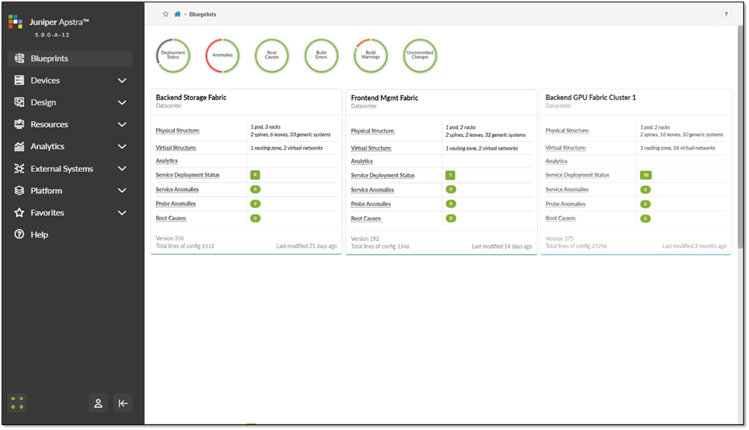
The Apstra Blueprints for the Frontend, Storage Backend, and GPU backend for cluster 1 and cluster 2 fabrics have been created and can be seen in the Blueprint tab, as shown in Figure 17. We will show the steps to create GPU backend for cluster 2 blueprint as an example. Similar steps should be followed to set up the Frontend and Storage Backend fabrics. The configurations for these are included in the Terraform repository described in the next section.
Figure 17: AI Fabric Blueprints in Apstra
Setting up the Apstra Server and Apstra ZTP Server
A configuration wizard launches upon connecting to the Apstra server VM for the first time. At this point, passwords for the Apstra server, Apstra UI, and network configuration can be configured.
For more detailed information about installation and step-by-step configuration with Apstra, refer to the Juniper Apstra User Guide. Additional guidance in this walkthrough is provided in the form of notes.
Onboarding devices in the Apstra WEB UI
There are two methods for adding Juniper devices into Apstra: manually (recommended method) or in bulk using ZTP.
To add devices manually:
- In the Apstra UI navigate to Devices >> Agents >> Create Offbox Agents:
- This requires that the devices are preconfigured with a root password, a management IP and proper static routing if needed, as well as ssh Netconf, so that they can be accessed and configured by Apstra.
To add devices via ZTP:
- From the Apstra ZTP server, follow the ZTP steps described in the Juniper Apstra User Guide.
It is best practice to avoid setting loopbacks, interfaces (except management interface), routing-instances (except management-instance) or any other settings as part of this baseline configuration.
Apstra sets the protocols LLDP and RSTP when the device is successfully Acknowledged.
The QFX5240 devices were onboarded using the manual method following these steps in the Apstra Web UI:
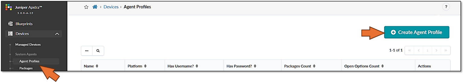
Step 1: Create Agent Profile.
To create an Agent Profile, navigate to Devices >> Agent Profiles and then click on Create Agent Profile.
Figure 18. Create Agent Profile in Apstra
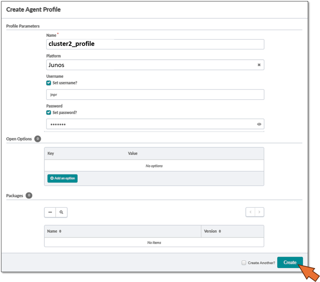
Enter the Agent profile name, select platform (Junos), and enter the username and password that will be used by Apstra to communicate with the devices. Make sure the devices are configured with these same username and password and have ssh Netconf enabled under system services.
Figure 19: Apstra Agent Profile Parameters
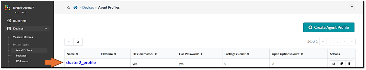
After entering the required information click Create and confirm Agent Profile creation.
Figure 20: New Apstra Agent Profile Verification
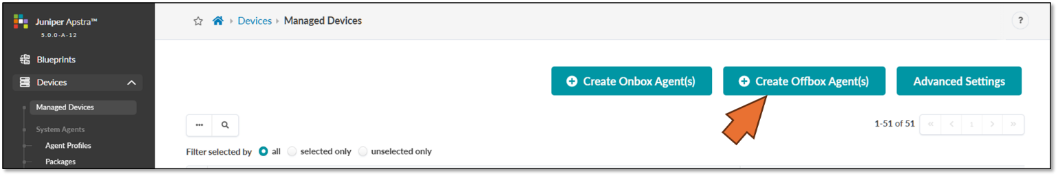
Step 2: Create Offbox Agents for QFX devices.
To create Offbox Agents for the QFX devices navigate to Devices >> Managed Devices and then click on Create Offbox Agents.
Make sure you select Offbox Agent(s).
Figure 21: Create Offbox Agent in Apstra
Identify the device(s) to onboard. You can enter a comma-separated list of hostnames, individual IP addresses, or IP address ranges. An IP address range allows you to onboard multiple devices at once.
Select the platform, and Agent Profile (select the profile created in the previous step).
Figure 22: Adding a Range of IP Addresses in Apstra
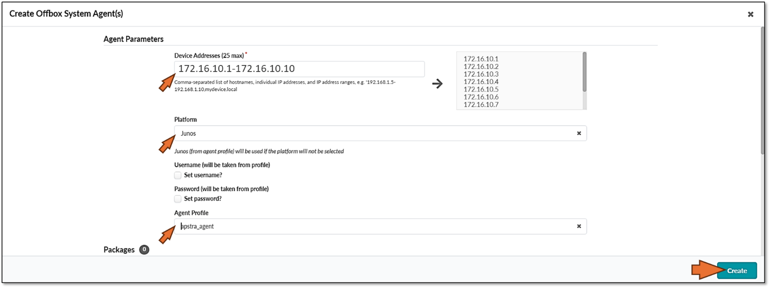
After entering the required information click Create.
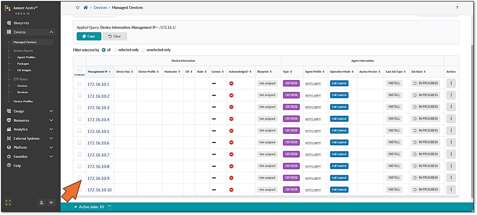
Confirm that the devices have been added for onboarding. Once the offbox agent has been created, devices will be added to the list of Managed Devices. Apstra will attempt to connect and if successful it will populate the relevant information.
Figure 23: New devices being onboarded
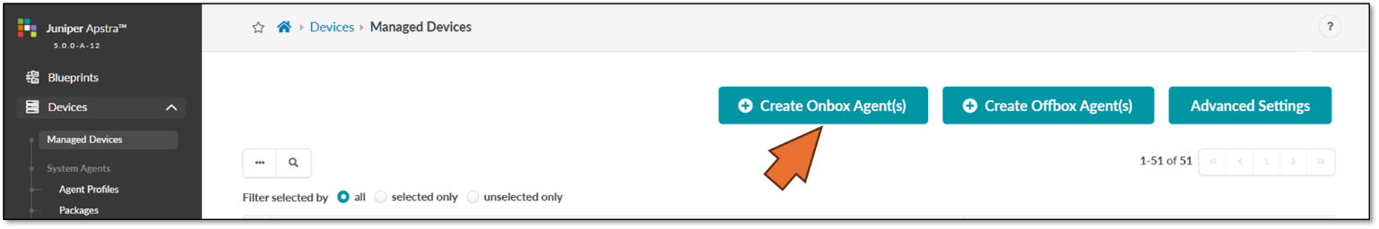
Step 3: Create Onbox Agents and onboard AMD servers.
To create onbox Agents for the AMD servers navigate to Devices >> Managed Devices and then click on Create Onbox Agents.
Make sure you select Onbox Agent(s).
Figure 24: Create Onbox Agent in Apstra
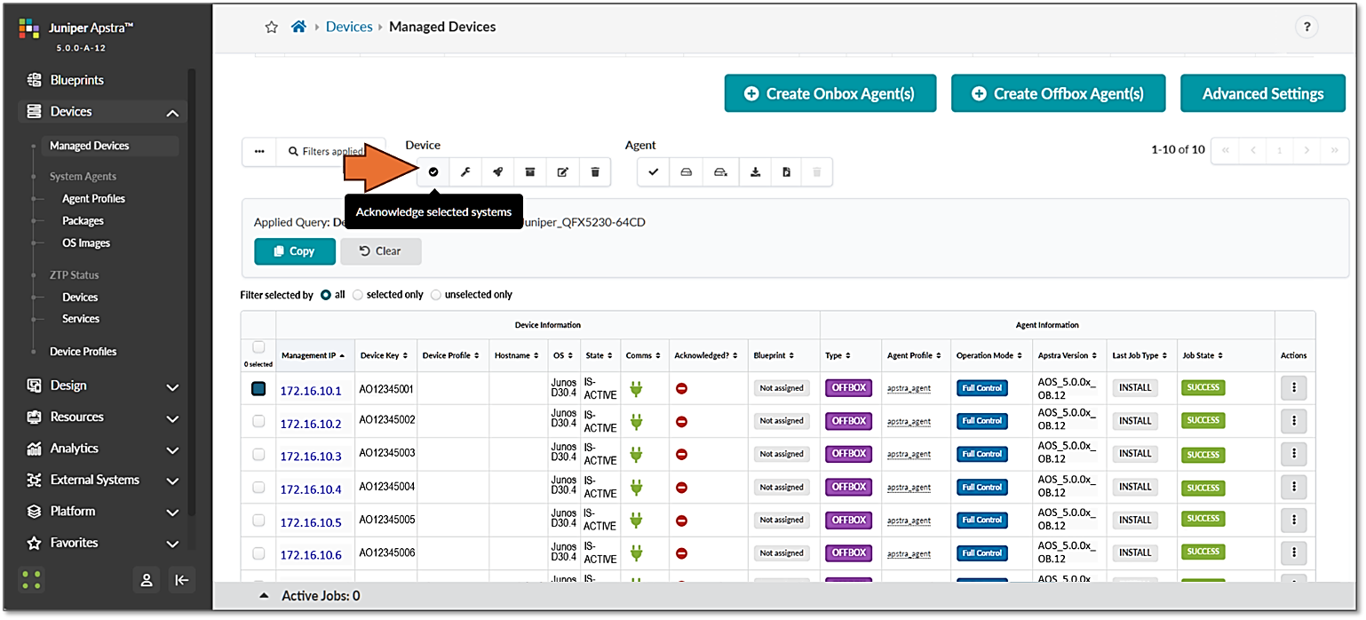
Step 4: Acknowledge Managed Devices for Use in Apstra Blueprints.
The devices must be acknowledged by the user to complete the onboarding and allow them to be part of Apstra Blueprints.
Figure 25: Acknowledging Managed Devices in Apstra Blueprints
Fabric Provisioning in the Apstra Web UI
The following steps outline the provisioning of the GPU Backend Fabric with Apstra.
Step 1: Create Interface Maps and Logical Devices for the QFX5240 devices.
Table 14. QFX5240-64DC port mappings
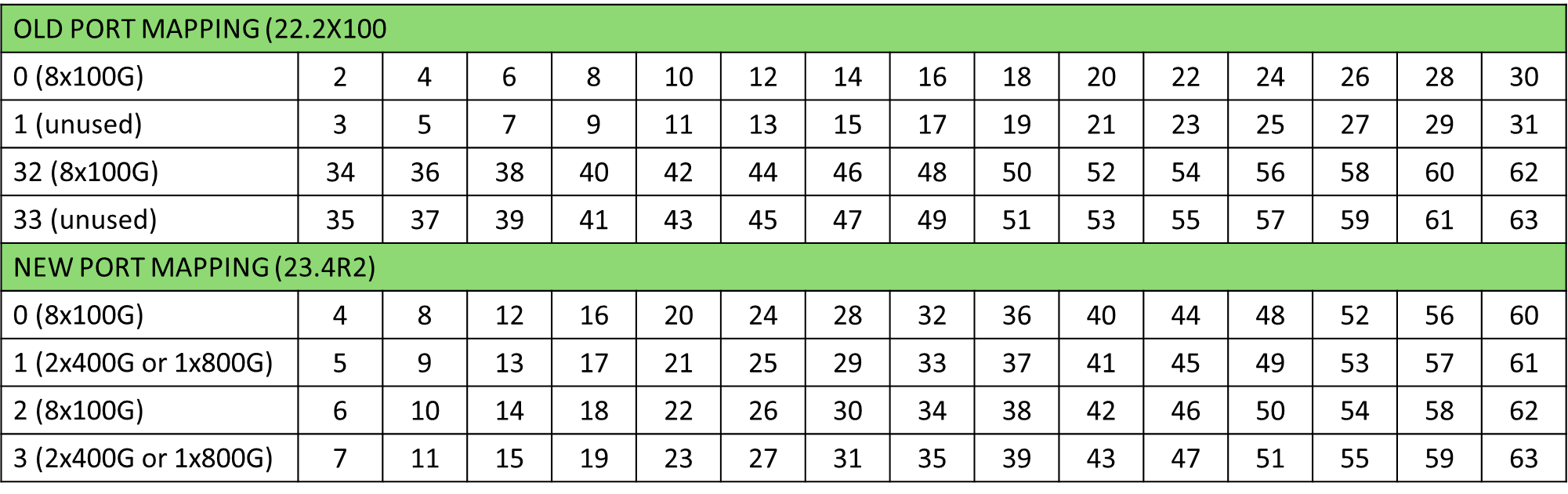
The Interface Map and Logical Devices for the QFX5240-64DC leaf and spine nodes were created following the new port mapping as shown in Figures 26-29
Figure 26: Apstra Interface Map for the QFX5240 Spine Nodes
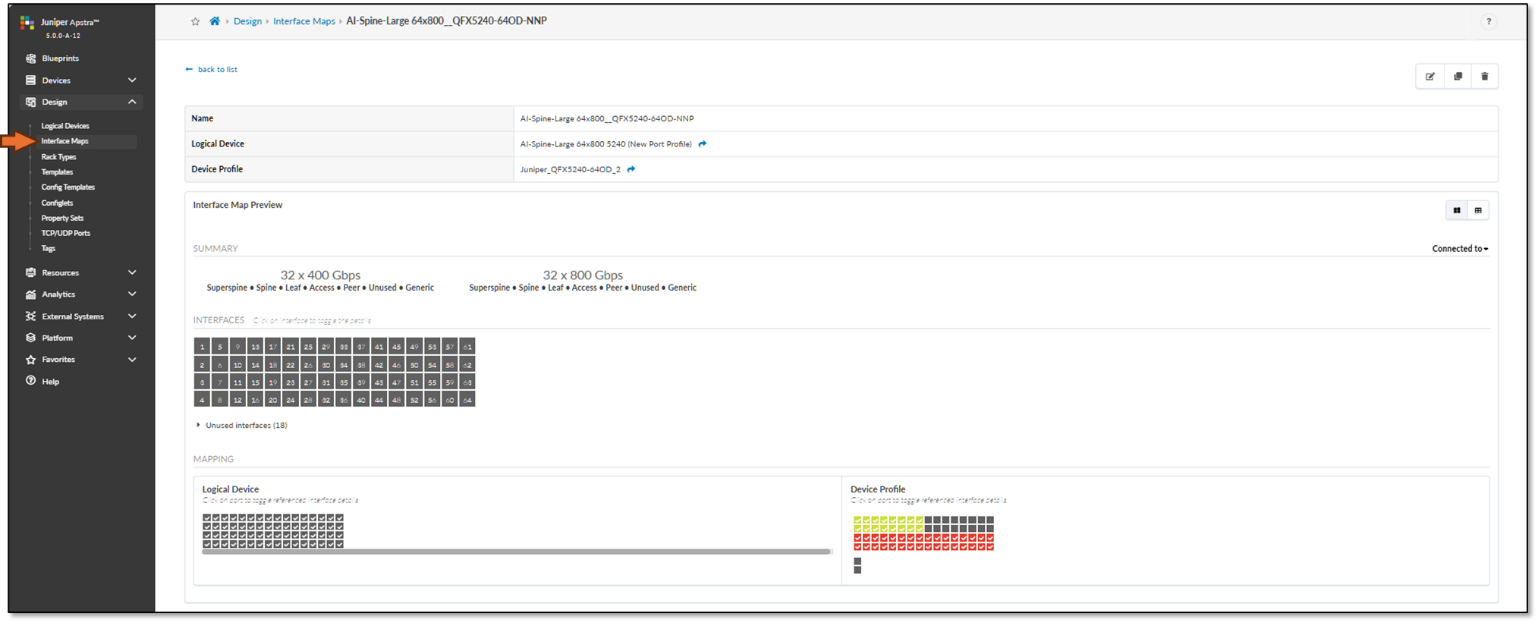
Figure 27: Apstra Logical Device for the QFX5240 Spine Nodes
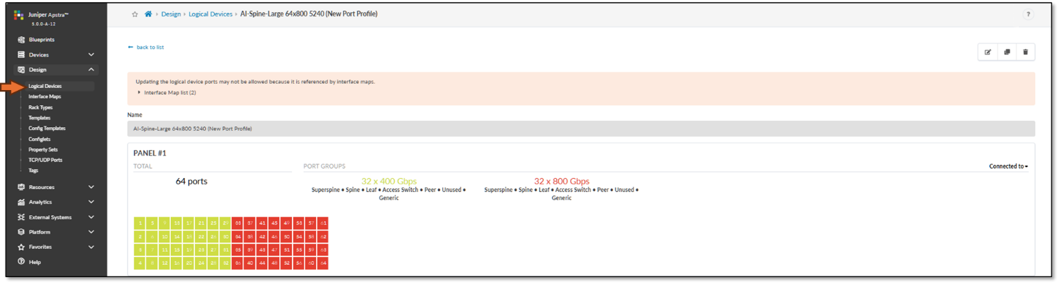
Figure 28: Apstra Interface Map for the QFX5240 Leaf Nodes
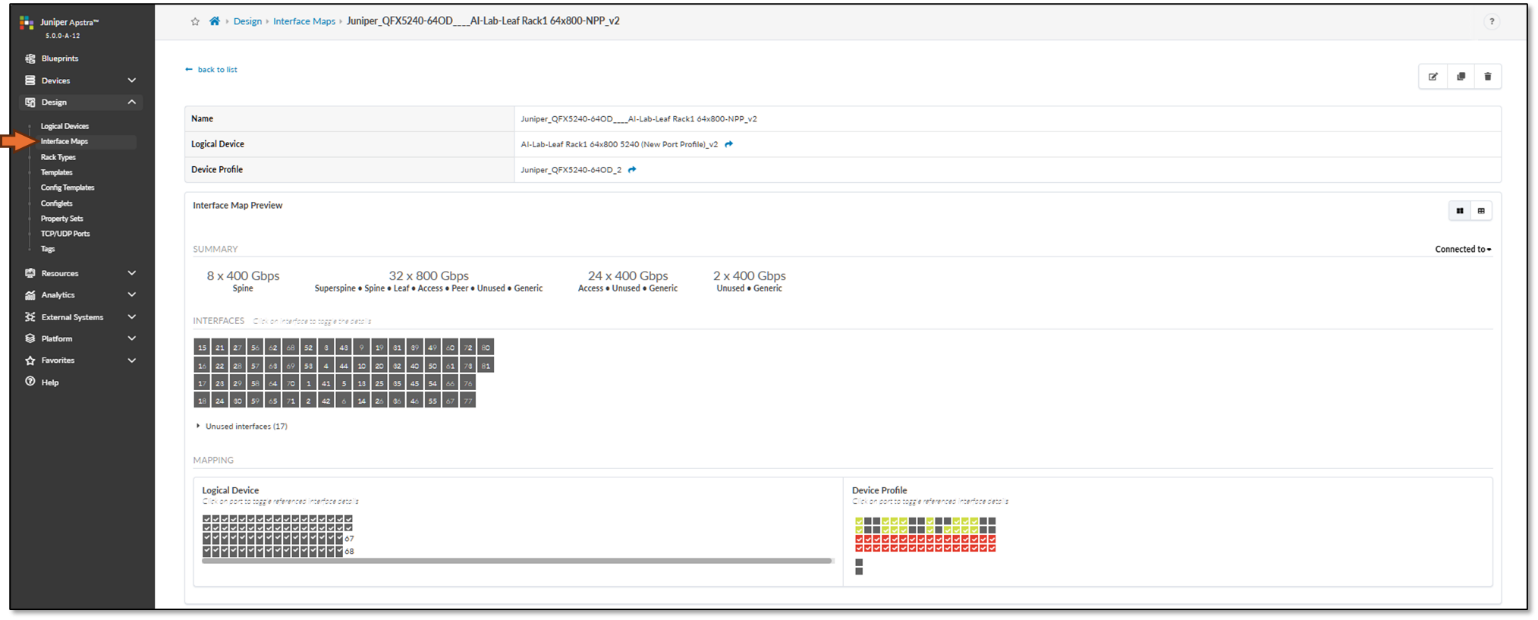
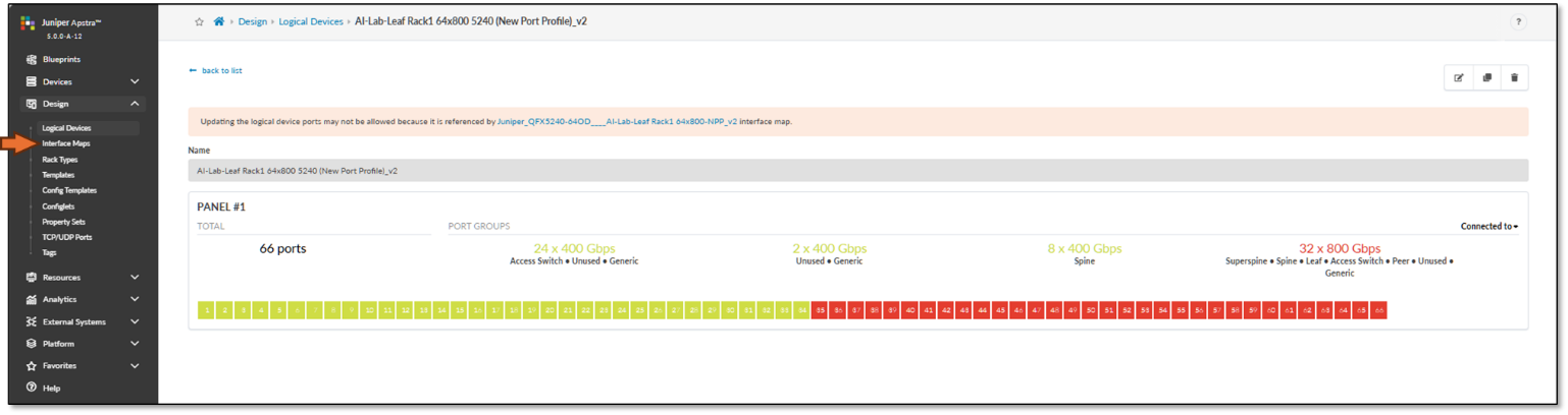
Figure 29: Apstra Logical Device for the QFX5240 Leaf Nodes
Step 2: Create Interface Map and Logical Device for the AMD GPU servers.
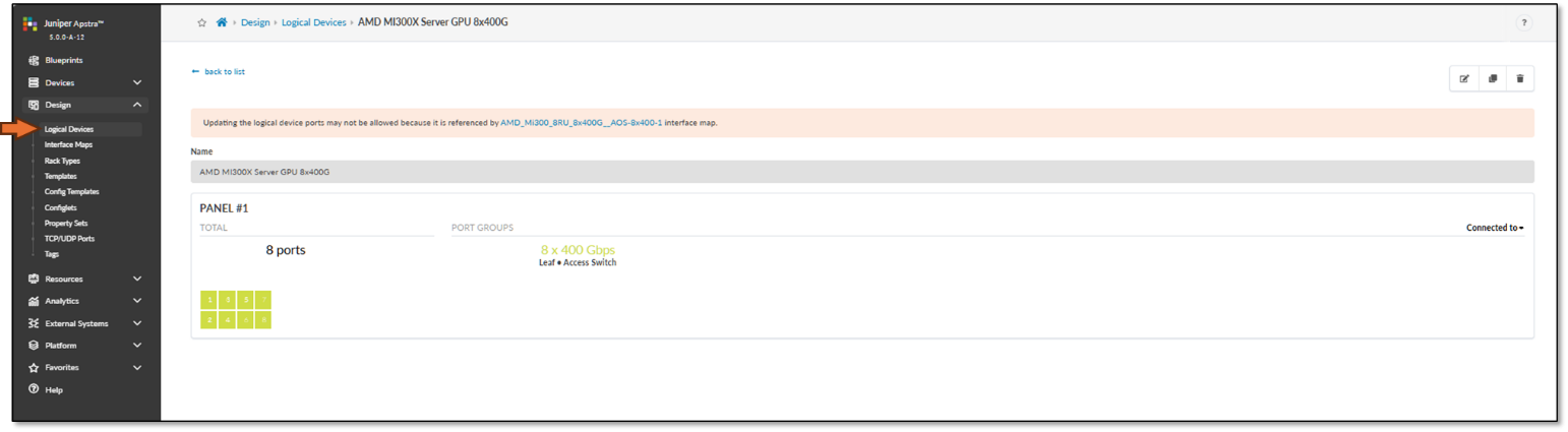
The logical Device and Interface Map for the AMD MI300X GPU servers are shown in Figures 30-31 respectively.
Figure 30: Apstra Interface Map for the AMD Servers
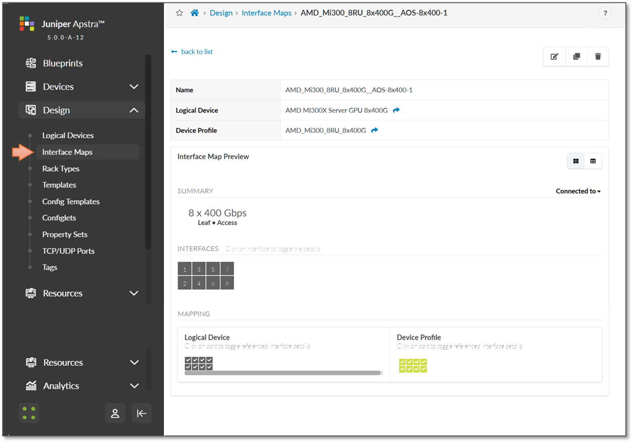
Figure 31: Apstra Logical Device for the AMD Servers
Step 3: Create Rack type.
In Apstra, a Rack is technically equivalent to a stripe in the context of an AI Fabric
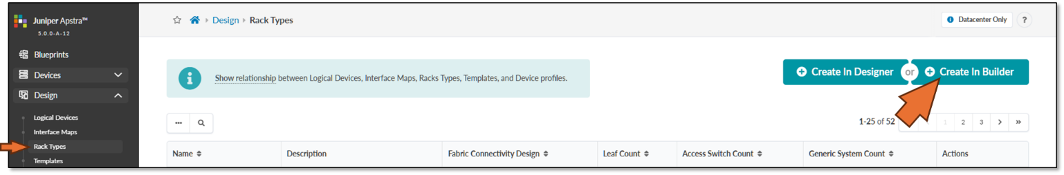
To create rack types and templates for the GPU Backend fabric, referencing the Logical Devices created in the previous step, navigate to Design → Rack Types → Create in Builder, as shown in Figure 32.
Figure 32: Create Rack Type in Apstra
Enter a Rack type, and description, and select L3 Clos.
Figure 33: Creating a Rack in Apstra using the Create In Builder option.
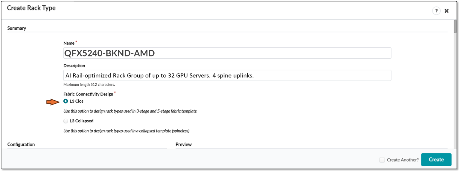
Figure 34: Creating a Rack in Apstra using the Create In Builder option - Leaf nodes details
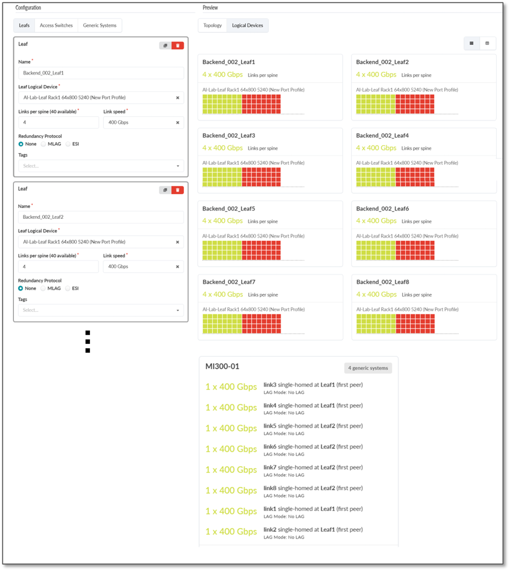
Under the Generic Systems tab add the MI300X devices and reference the logical device created in the previous step, as shown in Figure 35.
Figure 35: Creating a Rack in Apstra using the Create In Builder option – Generic Systems (GPU servers) details
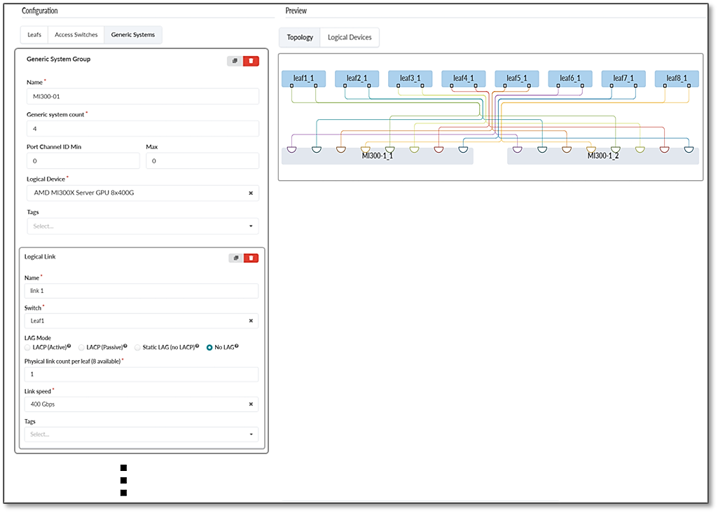
Notice that as you add the devices, the preview section on the right side will be updated. You can choose between viewing Logical Devices (Figures 34) or Topology (Figures 35).
Also, the topology created by Apstra follows the rail optimized architecture, which is a new feature introduced in Apstra.
Step 4: Create Template.
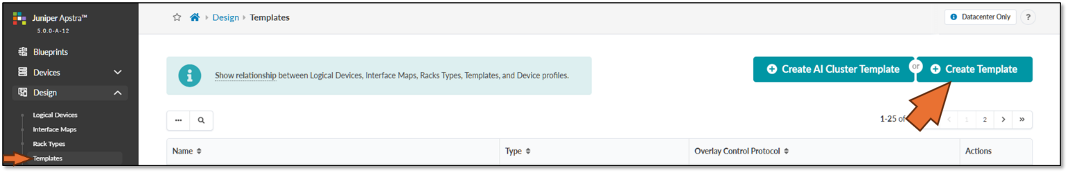
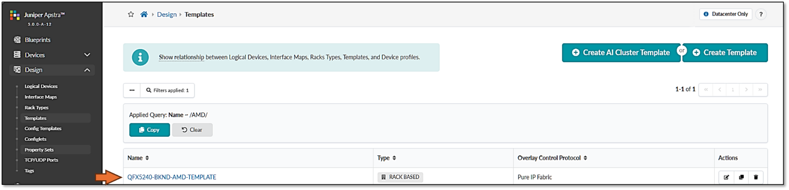
To create a template that references the QFX5240 rack type created in the previous step, navigate to Design -> Templates -> Create Template as shown in Figure 36.
Figure 36: Create Apstra Template
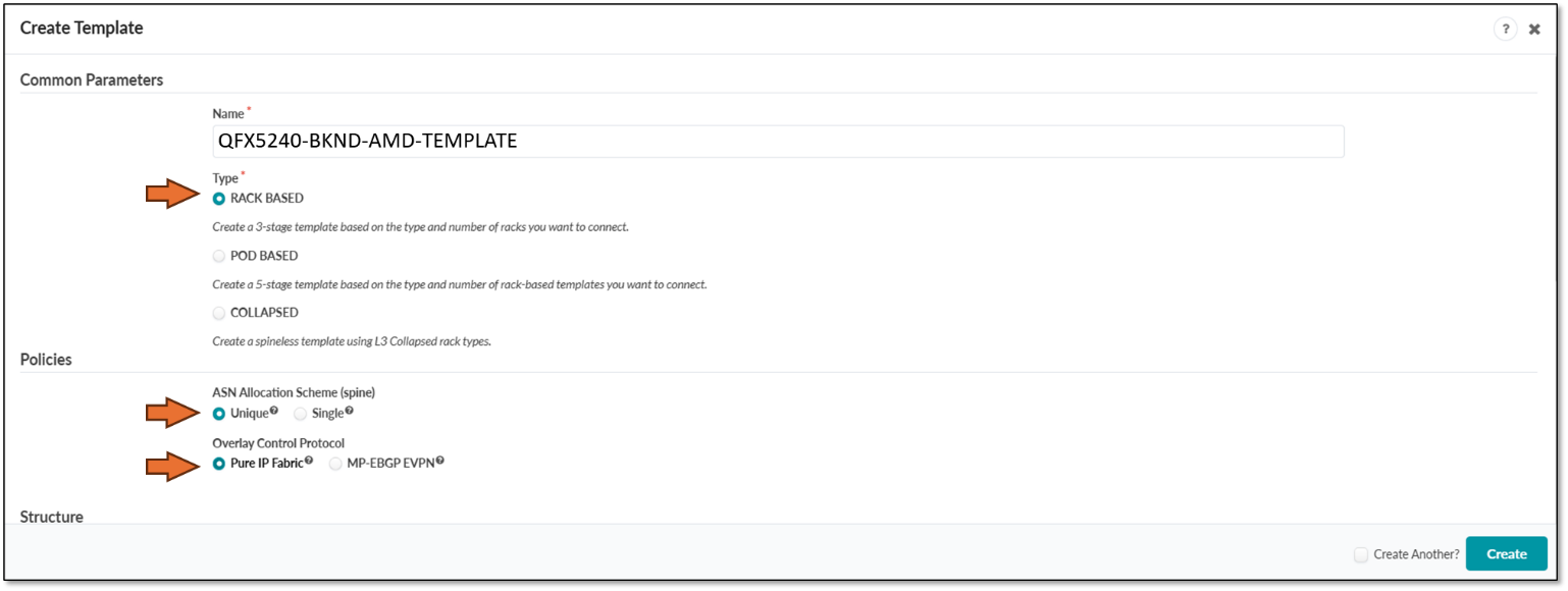
Enter the name of the template, and select Type RACK BASED, policies ASN allocation Unique, and Overlay Pure IP Fabric.
Figure 37: Creating a Template in Apstra - Parameters
Scroll down and select the Rack type and Spine logical device created in previous steps, set the number of Racks (which is equivalent to saying two stripes) as 2, and the number of spines as 4. Click on create when ready, as shown in Figure 38.
Figure 38: Creating a Template in Apstra - Structure
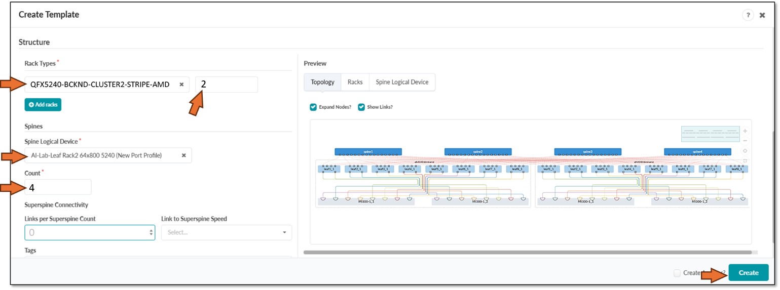
Figure 39: Verifying new template creation
Step 5: Create Configlets for DCQCN and DLB.
In the Apstra version used for this JVD, features such as ECN, PFC (DCQCN), and DLB are not natively available. Therefore, Apstra configlets should be used to add these features to the configurations before they are deployed to the fabric devices.
The configlet used for the DCQCN and DLB features on the QFX leaf nodes is as follows:
/* DLB configuration for Thor NIC2 Adapter */
hash-key {
    family inet {
        layer-3;
        layer-4;
    }
}
enhanced-hash-key {
    ecmp-dlb {
        flowlet {
            inactivity-interval 128;
            flowset-table-size 2048;
        }
        ether-type {
            ipv4;
            ipv6;
        }
        sampling-rate 1000000;
    }
}
protocols {
    bgp {
        global-load-balancing {
            load-balancer-only;
        }
    }
}
/* DCQCN configuration */
classifiers {
    dscp mydscp {
        forwarding-class CNP {
            loss-priority low code-points 110000;
        }
        forwarding-class NO-LOSS {
            loss-priority low code-points 011010;
        }
    }
}
drop-profiles {
    dp1 {
        interpolate {
            fill-level [ 55 90 ];
            drop-probability [ 0 100 ];
        }
    }
}
    shared-buffer {
        ingress {
       buffer-partition lossless {
          percent 66;
          dynamic-threshold 10;
       }
       buffer-partition lossless-headroom {
          percent 24;
       }
       buffer-partition lossy {
          percent 10;
       }
      }
      egress {
        buffer-partition lossless {
           percent 66;
        }
        buffer-partition lossy {
           percent 10;
        }
      }
    }
forwarding-classes {
    class CNP queue-num 3;
    class NO-LOSS queue-num 4 no-loss pfc-priority 3;
}
congestion-notification-profile {
    cnp {
        input {
            dscp {
                code-point 011010 {
                    pfc;
                }
           }
        }
        output {
            ieee-802.1 {
                code-point 011 {
                    flow-control-queue 4;
                }
            }
        }
    }
}
interfaces {
    et-* {
        congestion-notification-profile cnp;
        scheduler-map sm1;
        unit * {
            classifiers {
                dscp mydscp;
            }
        }
    }
}
scheduler-maps {
    sm1 {
        forwarding-class CNP scheduler s2-cnp;
        forwarding-class NO-LOSS scheduler s1;
    }
}
schedulers {
    s1 {
        drop-profile-map loss-priority any protocol any drop-profile dp1;
        explicit-congestion-notification;
    }
    s2-cnp {
        transmit-rate percent 5;
        priority strict-high;
    }
}
The configlet used for the DCQCN and DLB features on the QFX spine nodes is as follows:
/* DLB configuration */
hash-key {
family inet
layer-3;
layer-4;
}
}
enhanced-hash-key {
ecmp-dlb {
flowlet {
inactivity-interval 128;
flowset-table-size 2048;
}
ether-type {
ipv4;
ipv6;
}
sampling-rate 1000000;
}
}
protocols {
bgp {
global-load-balancing {
helper-only;
}
}
}
/* DCQCN configuration */
class-of-service {
classifiers {
dscp mydscp {
forwarding-class CNP {
loss-priority low code-points 110000;
}
forwarding-class NO-LOSS {
loss-priority low code-points 011010;
}
}
}
drop-profiles {
dp1 {
interpolate {
fill-level [ 55 90 ];
drop-probability [ 0 100 ];
}
}
}
shared-buffer {
ingress {
buffer-partition lossless {
percent 66;
dynamic-threshold 10;
}
buffer-partition lossless-headroom {
percent 24;
}
buffer-partition lossy {
percent 10;
}
}
egress {
buffer-partition lossless {
percent 66;
}
buffer-partition lossy {
percent 10;
}
}
}
forwarding-classes {
class CNP queue-num 3;
class NO-LOSS queue-num 4 no-loss pfc-priority 3;
}
congestion-notification-profile {
cnp {
input {
dscp {
code-point 011010 {
pfc;
}
}
}
output {
ieee-802.1 {
code-point 011 {
flow-control-queue 4;
}
}
}
}
}
interfaces {
et-* {
congestion-notification-profile cnp;
scheduler-map sm1;
unit * {
classifiers {
dscp mydscp;
}
}
}
}
scheduler-maps {
sm1 {
forwarding-class CNP scheduler s2-cnp;
forwarding-class NO-LOSS scheduler s1;
}
}
schedulers {
s1 {
drop-profile-map loss-priority any protocol any drop-profile dp1;
explicit-congestion-notification;
}
s2-cnp {
transmit-rate percent 5;
priority strict-high;
}
}
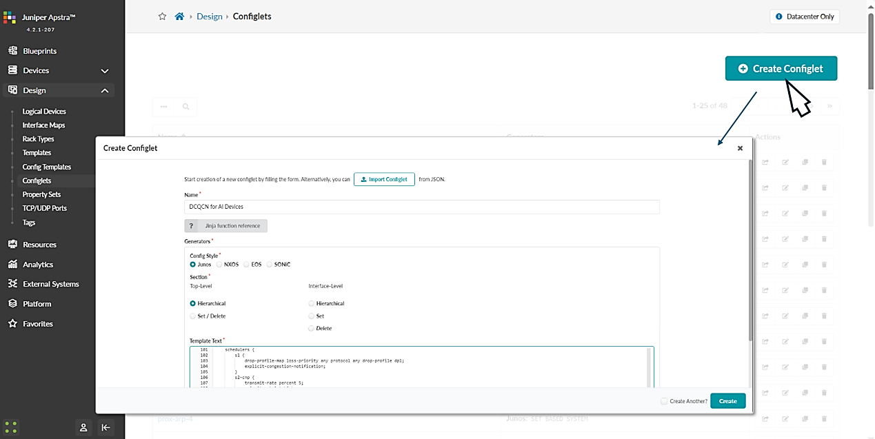
}To create these configlets navigate to:
Design -> Configlets -> Create Configlet and click on Create configlet.
Provide a name for the configlet, select the operating system, vendor and configuration mode and paste the above configuration snippet on the template text box as shown below:
Figure 40: DCQCN Configlet Creation in Apstra
Step 6: Create the GPU Backend Fabric Blueprint.
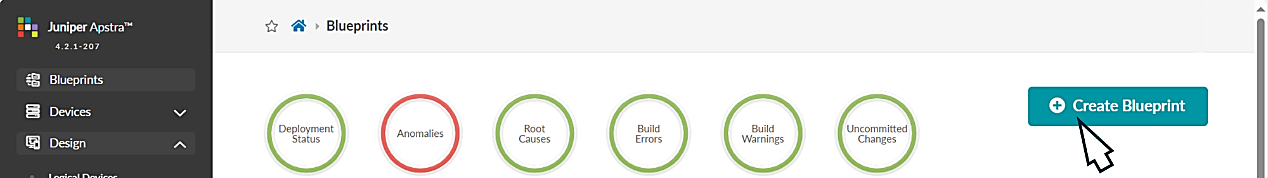
Navigate to the Blueprints section and click on Create Blueprint, as shown in Figure 41.
Figure 41: Creating a Blueprint in Apstra
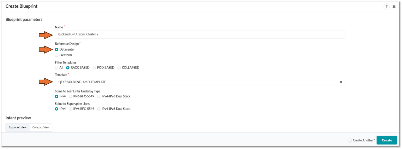
Provide a name for the new blueprint, select data center as the reference design, and select Rack-based. Then select the template that was created in the previous step. You can review the Intent preview before clicking Create.
Figure 42: New Blueprint Attributes in Apstra
Once the blueprint is successfully initiated by Apstra, it will be included in the Blueprint dashboard as shown below.
Figure 43: New Blueprint Added to Blueprint Dashboard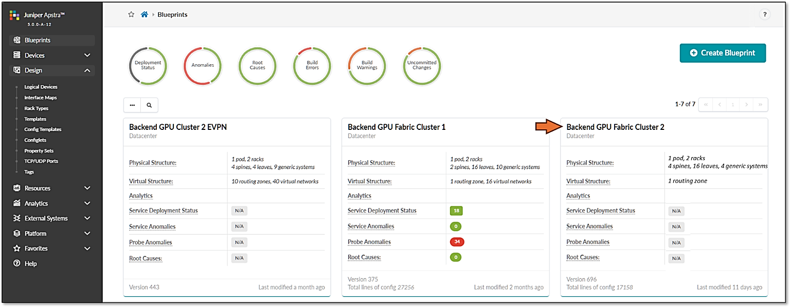
Notice that the Deployment Status, Service Anomalies, Probe Anomalies and Root Causes are all shown as N/A. This is because you will need to complete additional steps that include mapping the different roles in the blueprint to the physical devices, defining which interfaces will be used, etc.
When you click on the blueprint name and enter the blueprint dashboard it will indicate that the blueprint has not been deployed yet.
Figure 44: New Blueprint’s dashboard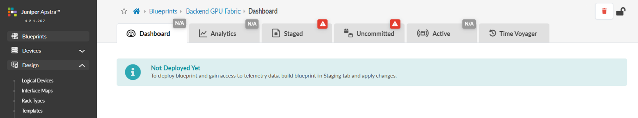
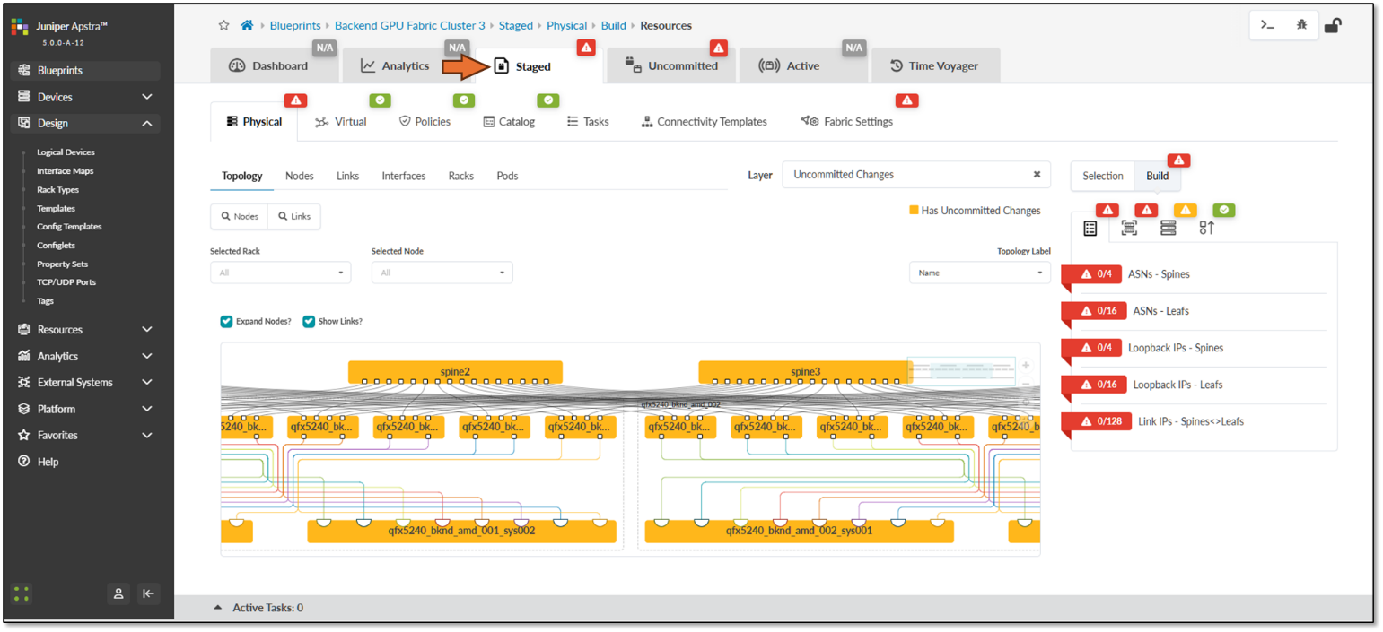
The Staged view, as depicted in Figure 40, shows that the topology is correct, but attributes such as mandatory ASNs and loopback addresses for the spines and the leaf nodes, and the spine to leaf links addressing must still be provided by the user.
Figure 45: Undeployed Blueprint Dashboard
You will need to edit each one of these attributes and select from predefined pools of addresses and ASNs, as shown in the example on Figure 46, to fix this issue.
Figure 46: Selecting ASN Pool for Spine Nodes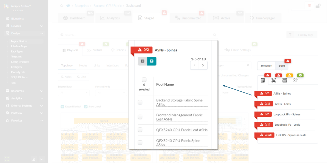
You will also need to select Interface Maps for each device’s role and along with assignment of system IDs as shown in Figures 47-48.
Figure 47: Mapping Interface Maps to Spine Nodes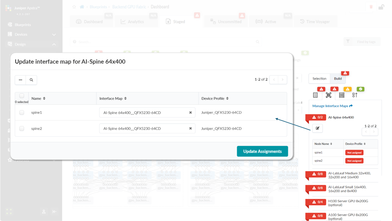
Figure 48: Mapping Spine Nodes to Physical Devices (System
IDs)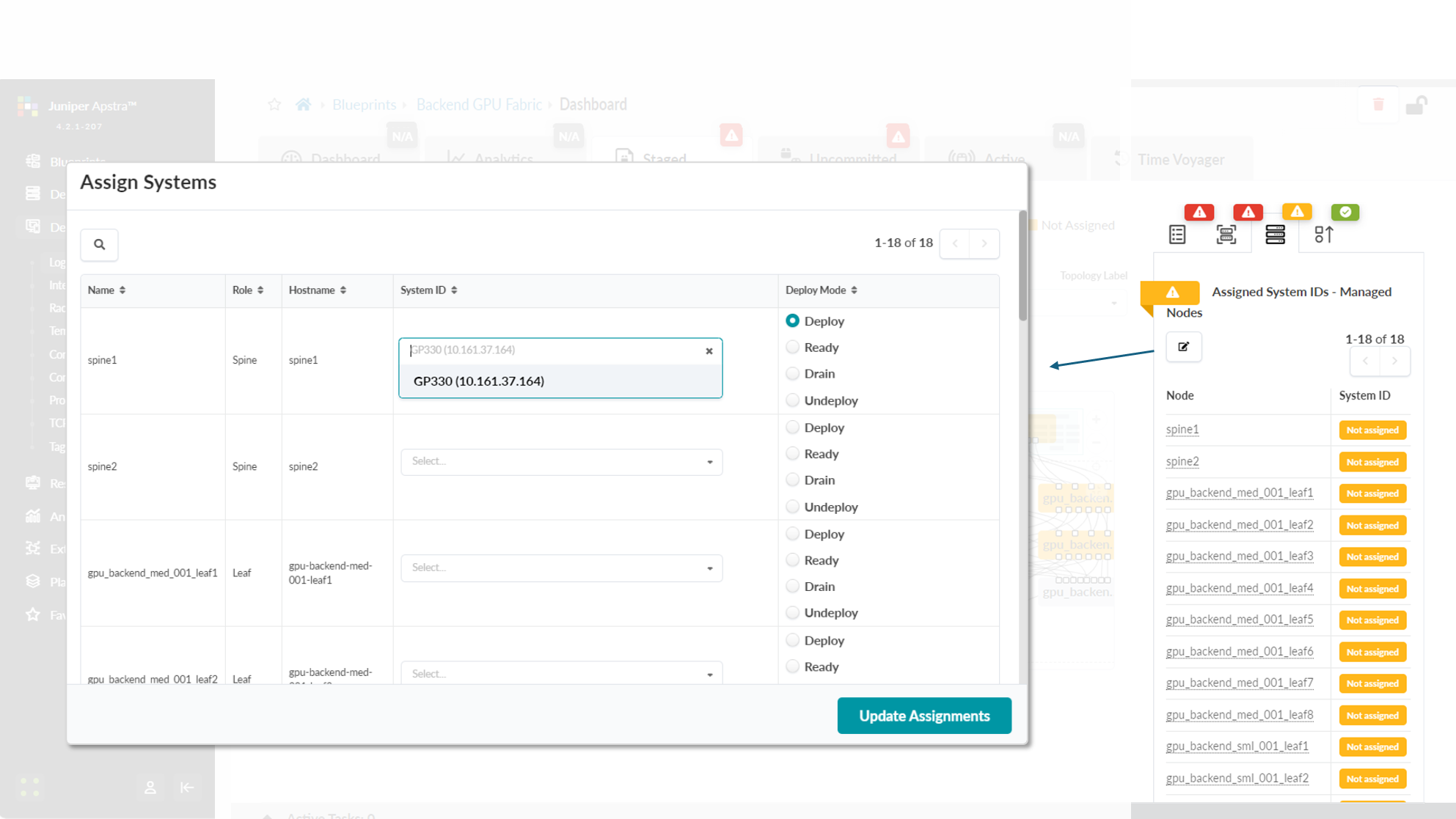
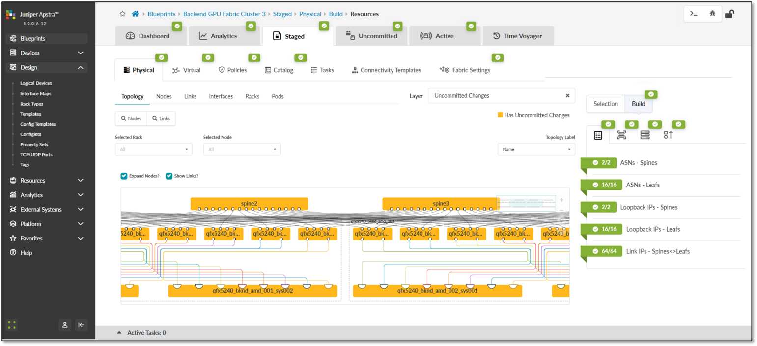
Once all these steps are completed, you can commit the changes, and Apstra will generate and push the vendor and device-type specific configurations to all devices in the blueprint. After this process is complete, the fabric should be successfully deployed, as indicated by the green checkmarks shown in Figure 49.
Figure 49: Active Blueprint.
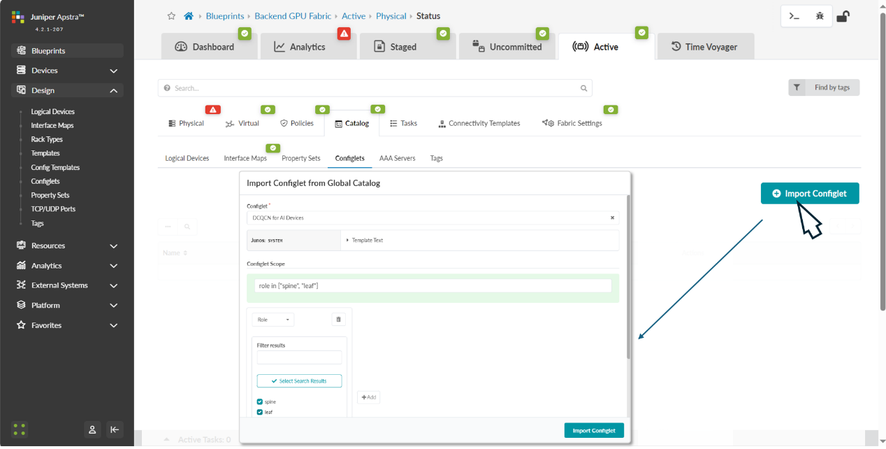
Step 7: Apply the configlets previously created to the Blueprint.
The configlet should be applied to the devices, both leaf and spine roles within the blueprint.
Navigate back to the blueprint dashboard and the move to Staged -> Catalog -> Import.
Select the configlet you want to apply, and the device role where you want to apply it.
Figure 50: Applying DCQCN Configlets to Devices in Apstra
After successfully importing the configlet into the blueprint it should be listed in the catalog. You need to commit the changes for the configuration to be deployed to the devices.
Figure 51: Applying DCQCN Configlets to Devices in Apstra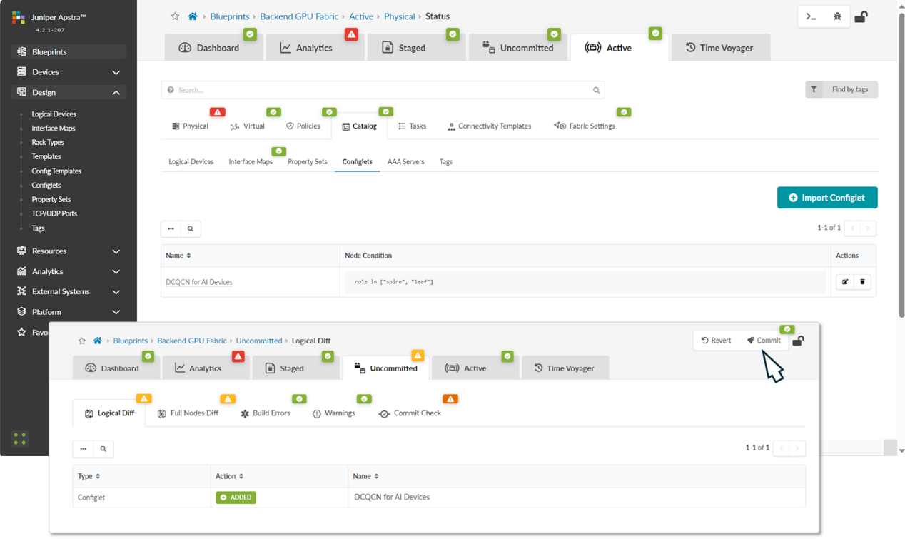
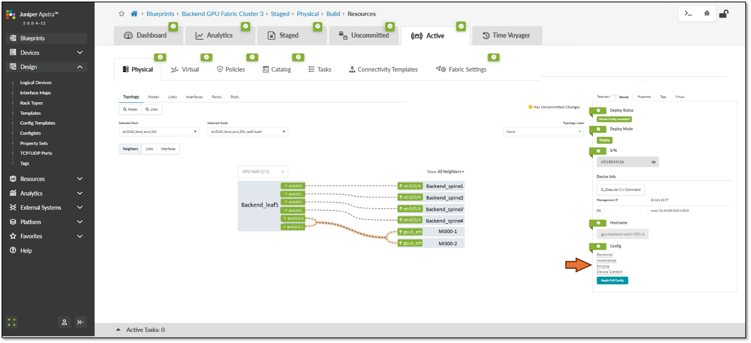
You can quickly check the status and the deployed configuration by clicking on each device in the Active tab and selecting the rendered config under the Device tab on the right side.
Figure 52: Device configuration verification in Apstra