APPENDIX: CRB Fabric Verification (Optional)
You may skip this optional chapter if you want. This information is presented to show more of the internal details on how the fabric is working.
Verification of the Campus Fabric Core-Distribution CRB deployment. See Figure 1. Currently, there are two desktops to validate the fabric. Let’s take a quick look to see if Desktop1 can connect internally and externally.
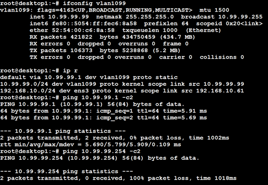
In this Fabric type you can also ping the additional static IP addresses assigned to each core switch along with the virtual gateway IP address. Try to ping 10.99.99.2 (on Core1) and 10.99.99.3 (on Core2), as well.
Validation steps:
- Confirmed local IP address, VLAN, and default gateway were configured on Desktop1.
- Can ping default gateway – indicates that we can reach the core switch.
- Ping to WAN router failed (10.99.99.254) – we need to troubleshoot.
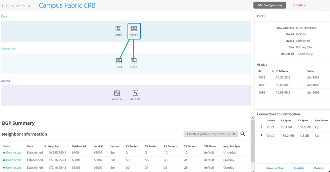
Start by validating the campus fabric in the portal by selecting the Campus Fabric option under the Organization tab on the left side of the portal.

Remote shell access into each device within the campus fabric is supported here as well as a visual representation of the following capabilities:
- BGP peering establishment.
- Transmit and receive traffic on a link-by-link basis.
- Telemetry, such as LLDP, from each device that verifies the physical build
BGP Underlay
Purpose
Verifying the state of eBGP between the core and distribution layers is essential for EVPN-VXLAN to operate as expected. This network of point-to-point links between each layer supports:
- Load balancing using ECMP for greater resiliency and bandwidth efficiencies.
- BFD to decrease convergence times during failures.
- Loopback reachability to support VXLAN tunnelling.
Without requiring verification at each layer, the focus can be on Dist1 and 2 and their eBGP relationships with Core1 and 2. If both distribution switches have established eBGP peering sessions with both core switches, you can move to the next phase of verification.
Due to the automated assignment of loopback IP addresses, for this fabric, we have the following configuration to remember:
| Switch Type | Switch Name | Auto assigned Loopback IP |
|---|---|---|
| Core | Core1 | 172.16.254.2 |
| Core | Core2 | 172.16.254.1 |
| Distribution | Dist1 | 172.16.254.3 |
| Distribution | Dist2 | 172.16.254.4 |
| Access | Access1 | N/A |
| Access | Access2 | N/A |
Action
Verify that BGP sessions are established between core devices and distribution devices to ensure loopback reachability, BFD session status, and load-balancing using ECMP.
Operational data can be gathered through the campus fabric section of the portal as Remote Shell or using an external application such as SecureCRT or Putty.
Verification of BGP Peering
Dist1:
Access the Remote Shell via the lower-right of the campus fabric, from the switch view, or via Secure Shell (SSH).
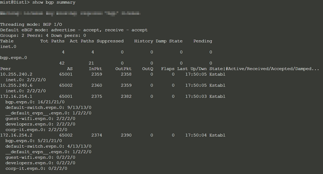
From the BGP summary, we can see that the underlay (10.255.240.X) peer relationships are established, which indicates that the underlay links are attached to the correct devices and the links are up.
It also shows the overlay (172.16.254.x) relationships are established and that it is peering at the correct loopback addresses. This demonstrates underlay loopback reachability.
We can also see routes received; time established are roughly equal which looks good so far.
The campus fabric build illustrates per device real-time BGP peering status shown below from Dist1:
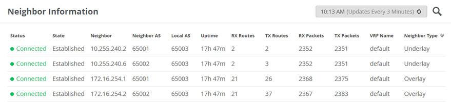
If BGP is not established then go back and validate the underlay links and addressing, and that the loopback addresses are correct. Loopback addresses should be pingable from other loopback addresses.
Verification of BGP connections can be performed on any of the other switches (not shown).
The primary goal of eBGP in the underlay is to provide loopback reachability between core and distribution devices in the campus fabric. This loopback is used to terminate VXLAN tunnels between devices. The following shows loopback reachability from Dist1 to all devices in the campus fabric:
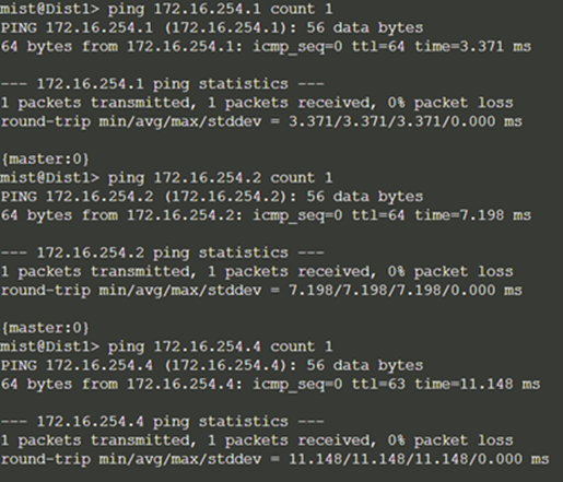
eBGP sessions are established between core-distribution layers in the campus fabric. Loopback reachability has also been verified between core and distribution devices.
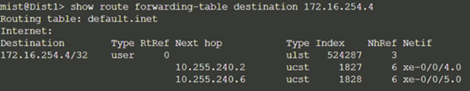
Let’s verify that the routes are established to the core and other devices across multiple paths. For example, Dist1 should leverage both paths through Core1 and 2 to reach Dist2 and vice versa.
Dist1: ECMP Loopback reachability to Dist2 through Core1/2
Dist2: ECMP Loopback reachability with Dist1 through Core1/2
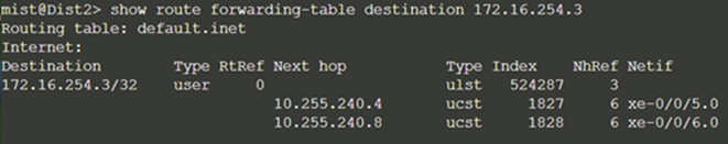
This can be repeated for Core1 and 2 to verify ECMP load balancing.
Finally, we validate BFD for fast convergence in the case of a link or device failure:
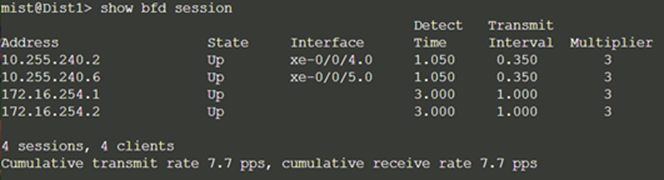
Conclusion: At this point, the BGP underlay and overlay are operational through the verification of eBGP between corresponding layers of the campus fabric and loopback routes are established between core and distribution layers.
EVPN VXLAN Verification Between Core and Distribution Switches
Since the desktop can ping its default gateway, we can assume the Ethernet switching tables are correctly populated, and VLAN and interface modes are correct. If pinging the default gateway failed, then troubleshoot underlay connectivity.
Verification of the EVPN Database on Both Core Switches
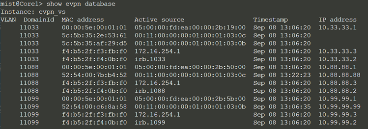
Core1:
Core2:
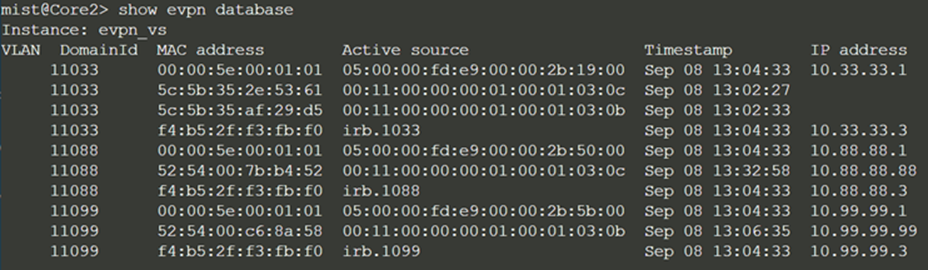
Both core switches have identical EVPN databases which is expected. Notice the entries for desktop1 (10.99.99.99) and desktop2 (10.88.88.88) present on each core switch. These entries are learned through the campus fabric from the ESI-LAGs off Dist1 and 2.
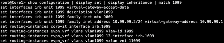
The 10.99.99.99 IP address is associated with irb.1099 and we see a VNI of 11099. Let's just double-check VLAN to VNI mapping on the distribution and core switches and verify the presence of L3 on the distribution switches.
Distribution:

Core:
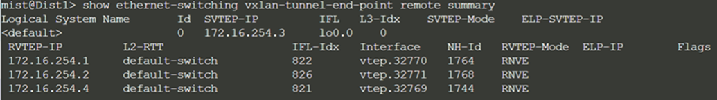
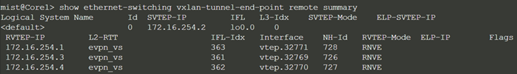
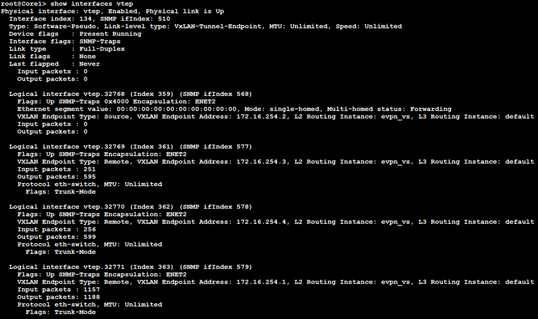
Verification of VXLAN Tunnelling Between Distribution and Core Switches
Dist1:
Core1:
Finally, validate that Core1 is receiving Desktop 1’s MAC address through MP-BGP via Type 2 EVPN routes:
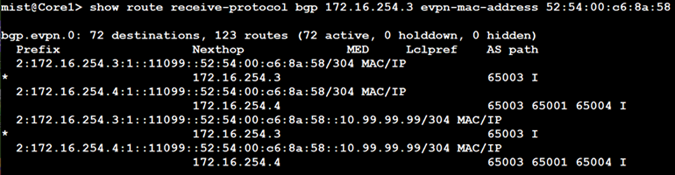
The EVPN database is confirmed on both Core1 and 2 and VXLAN tunnels are established between distribution and core switches. We have also verified Desktop1 and 2 are present in Core1 and 2’s EVPN databases.
Next, we verify if Desktop1’s MAC address is mapped to the correct VTEP interface on Core1:
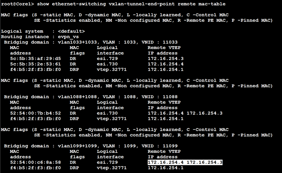
Notice Desktop1’s MAC address (52:54:00:c6:8a:58) is learned through both Dist1 and 2 switches.
Now, we verify if the core has Desktop1 and Desktop 2’s MAC and ARP entries:
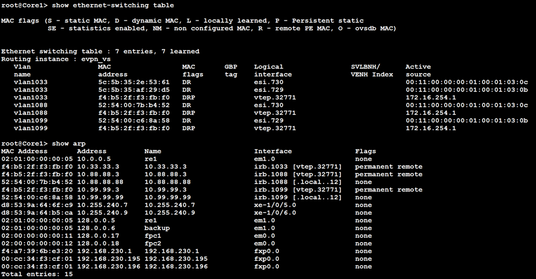
From an EVPN-VLAN perspective, everything is correct. This includes the fact that both Desktop addresses are present, which verifies campus fabric connectivity. Maybe we are looking in the wrong place. Let's look at the connection between the core and the WAN router.