High Availability Design for SRX Series Firewalls
One of the most important considerations for WAN design is High Availability. High availability ensures business continuity and disaster recovery by maximizing the availability and increasing redundancy within and across different sites.
Juniper® SRX Series Firewall High Availability (HA) design example is for administrators who want to deploy HA Juniper SRX Series Firewall at the Edge, but not for Whitebox setups.
In this documentation, you’ll find step-by-step guidance for setting up a highly available hub and spoke deployment using SRX Series Firewalls. Since this HA deployment builds upon the configurations referenced in the Juniper® Mist WAN Assurance configuration, you'll need to configure your network with those settings first. In this example, you'll learn how to setup SRX Series Firewalls in an HA cluster configuration.
Overview
You will deploy a highly available Hub and Spoke as shown in Figure 1. Here we see the SRX Series highly available Juniper Mist WAN Assurance topology for this HA Design Guide.
Before you get started, be sure you’ve setup the topology described in the Juniper WAN Assurance Configuration Guide.
The topology uses one standalone and one high-available cluster setup of spoke and high-available cluster setup of hub on the other side.
The supported SRX Series high-available clustering for the WAN edge deployment requires local Layer2 adjacency for a spoke or a hub setup.
Before You Begin
- Understand how to configure high-availability cluster with SRX Series Firewalls.
- You'll need a dedicated HA-control interface that is defined by the device
type. This interface is connected usually using a patch cable between the
two devices. You must use the same port for HA control interface. To know
which port your device supports, see Understanding SRX Series Chassis Cluster
Slot Numbering and Physical Port and Logical Interface Naming.
The WAN edge configuration might automatically select the fabric interface next to the HA control interface. For details, log in https://manage.mist.com and refer documentation.
- You'll need a dedicated fabric-data interface. This interface is connected usually using a patchable between the two devices. For WAN edge configuration, selecting any port as fabric port is not supported. We recommend using the port the one next to the control port. Also see Chassis Cluster Fabric Interfaces.
- Similar to virtual chassis, the ports on the secondary node are renumbered after the formation of chassis cluster.
- Building the Cluster always involves the configuring two nodes and rebooting them after initial commands issues to build the cluster. See Example: Setting the Node ID and Cluster ID for Security Devices in a Chassis Cluster .
Interface Details for HA Cluster
Following samples show interfaces usage for the chassis cluster configuration.
Only the WAN1, WAN0 and LAN1 are changeable in the List below if they do not conflict with others which are not changeable.
Primary Node0 Interface Table Device MGMT (fxp0) HA Control Fabric Data WAN0 ZTP-IF WAN1 LAN1 LAN2 optional vSRX-N0 Mgmt em0 ge-0/0/0 ge-0/0/1 ge-0/0/3 ge-0/0/4 ge-0/0/5 SRX300-N0 ge-0/0/0 ge-0/0/1 ge-0/0/2 ge-0/0/7 ge-0/0/3 ge-0/0/4 ge-0/0/5 SRX320-N0 ge-0/0/0 ge-0/0/1 ge-0/0/2 ge-0/0/7 ge-0/0/3 ge-0/0/4 ge-0/0/5 SRX340-N0 Mgmt ge-0/0/1 ge-0/0/2 ge-0/0/0 ge-0/0/3 ge-0/0/4 ge-0/0/5 SRX345-N0 Mgmt ge-0/0/1 ge-0/0/2 ge-0/0/0 ge-0/0/3 ge-0/0/4 ge-0/0/5 SRX380-N0 Mgmt ge-0/0/1 ge-0/0/2 ge-0/0/0 ge-0/0/3 ge-0/0/4 ge-0/0/5 SRX550-N0 Mgmt ge-0/0/1 ge-0/0/2 ge-0/0/0 ge-0/0/3 ge-0/0/4 ge-0/0/5 SRX1500-N0 Mgmt ha_control ge-0/0/1 ge-0/0/0 ge-0/0/3 ge-0/0/4 ge-0/0/5 SRX4100-N0 Mgmt ha_control ha_data xe-0/0/0 xe-0/0/3 xe-0/0/4 xe-0/0/5 SRX4200-N0 Mgmt ha_control ha_data xe-0/0/0 xe-0/0/3 xe-0/0/4 xe-0/0/5 SRX4600-N0 Mgmt ha_control ha_data xe-1/0/0 xe-1/0/3 xe-1/0/4 xe-1/0/5
Once you configure chassis cluster and reboot both the nodes, the second node (node 1) renumbers its interfaces as shown in the following sample. You have to use the interface numbering when you configure the second WAN/LAN interface in the Juniper Mist portal.
Secondary Node1 Interface Table RENUMBERING Device MGMT (fxp0) HA Control Fabric Data WAN0 ZTP-IF WAN1 LAN1 LAN2 optional vSRX-N1 Mgmt em0 ge-7/0/0 ge-7/0/1 ge-7/0/3 ge-7/0/4 ge-7/0/5 SRX300-N1 ge-1/0/0 ge-1/0/1 ge-1/0/2 ge-1/0/7 ge-1/0/3 ge-1/0/4 ge-1/0/5 SRX320-N1 ge-3/0/0 ge-3/0/1 ge-3/0/2 ge-3/0/7 ge-3/0/3 ge-3/0/4 ge-3/0/5 SRX340-N1 Mgmt ge-5/0/1 ge-5/0/2 ge-5/0/0 ge-5/0/3 ge-5/0/4 ge-5/0/5 SRX345-N1 Mgmt ge-5/0/1 ge-5/0/2 ge-5/0/0 ge-5/0/3 ge-5/0/4 ge-5/0/5 SRX380-N1 Mgmt ge-5/0/1 ge-5/0/2 ge-5/0/0 ge-5/0/3 ge-5/0/4 ge-5/0/5 SRX550-N1 Mgmt ge-9/0/1 ge-9/0/2 ge-9/0/0 ge-9/0/3 ge-9/0/4 ge-9/0/5 SRX1500-N1 Mgmt ha_control ge-7/0/1 ge-7/0/0 ge-7/0/3 ge-7/0/4 ge-7/0/5 SRX4100-N1 Mgmt ha_control ha_data xe-7/0/0 xe-7/0/3 xe-7/0/4 xe-7/0/5 SRX4200-N1 Mgmt ha_control ha_data xe-7/0/0 xe-7/0/3 xe-7/0/4 xe-7/0/5 SRX4600-N1 Mgmt ha_control ha_data xe-8/0/0 xe-8/0/3 xe-8/0/4 xe-8/0/5
HA Interfaces
Each path and Node in an HA network require their own designated WAN interface. This ensures Active/Active usage, meaning that these interfaces stay active and engaged, no matter what. The WAN interfaces can contain either a static IP address or be linked to a DHCP-Lease, giving you flexibility in how you manage them.
In certain scenarios, you may be limited to just one WAN IP address, especially for MPLS Networks. In these cases, you can configure the interface as a shared VRRP interface between two Nodes. This sets up an Active/Passive usage of the links, maintaining the balance and ensuring continuity. A second IP address for that second node enhances your setup's performance even further.
Configure High Availability
You should have already configured Networks, Applications, Sites, Variables, Hub Profiles and WAN Edge Templates. If these steps are new to you, please follow the Mist WAN Configuration Guide first before proceeding with the HA design guide. See WAN Assurance Configuration Overview.
The following steps outline the process of creating high availability cluster.
Create a New Hub Profile
Now it’s time to add the second Node in your highly available Hub. In this next step, you’ll create a new Hub profile by cloning the existing one. Then, you’ll modify the clone to meet new requirements for the HA hub.
Create Spoke Template
With our HA Hubs in place, it’s time to create matching spoke templates, one spoke in standalone and the other in high availability cluster setup. We create the new spoke template by cloning the existing one and then modifying the cloned template. In this example, we clone the existing template called “Spokes”.
Create the Second Spoke Template
Now it’s time to clone our WAN Edge template for our redundant spoke node.
Onboard your Devices
We assume that you have your SRX Series Firewall already onboarded to the Juniper Mist™ cloud. We also assume that the physical connections such as cabling are already in place and that you are using valid interfaces for the high availability. All devices that are part of high availability cluster starts in standalone mode and the Mist cloud portal configuration enables devices to operate in cluster mode.
You can Claim or Adopt to onboard devices into your organization inventory. For details on getting your SRX Series Firewall up and running in the Mist cloud, see Cloud-Ready SRX Firewalls.
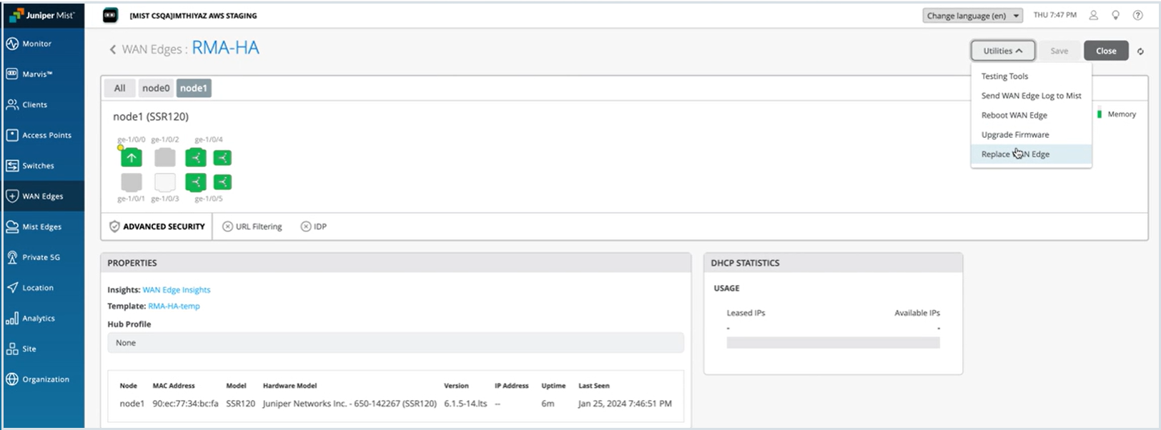
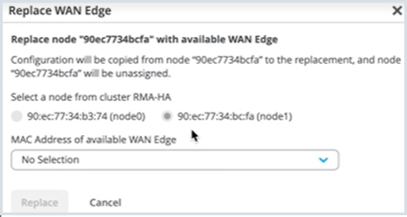
Replace an SRX Series Firewall Node in a High Availability Cluster
You can replace an SRX Series Firewall device from a high availability cluster setup with few simple steps.
Before you replace a SRX Series Firewall node from the cluster, you must:
- Remove the cluster fabric cables from the node being replaced and connect it to the new replacement node.
- Make sure that the replacement SRX Series Firewall is both the same model as the device being replaced and has a same Junos OS version.
Replace a Standalone SRX Series Firewall
You can replace connected or disconnected SRX Series Firewall with another SRX Series Firewall of the same model.