Switch Configuration Options
Use this information to configure your switches.
Overview
You can enter switch settings at the organization level or the site level.
-
To configure organization-wide settings, select Organization > Switch Templates from the left menu of the Juniper Mist portal. Then create your template and apply it to one or more sites or site groups.
To configure switch settings at the site level, select Site > Switch Configuration from the left menu of the Juniper Mist portal. Then select the site that you want to set up, and enter your switch settings.
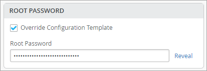
If an organization-level switch template was assigned to the site, the site configuration will appear in view-only mode. You can keep the settings from the template or make adjustments. In each section of the page, you can select Override Configuration Template and then enter your changes. These changes will apply only to this site, not to the template.
The following example shows how to override a template and set a site-specific root password.
The fields that support configuration through site variable have a help text showing the site variable configuration format underneath them. To configure site variables, follow the steps provided in Configure Site Variables. For more information about the switch configuration process and switch templates, see Configure Switches Using Templates.
At both the organization and site levels, the switch settings are grouped into sections as described below.
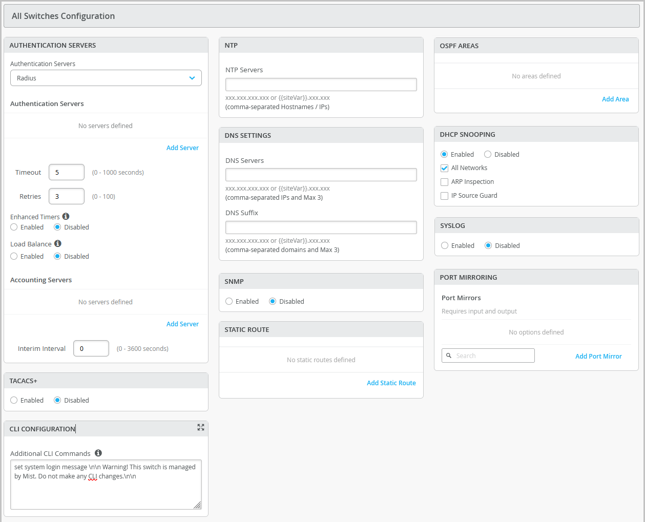
All Switches
Configure these options in the All Switches section of the Organization > Switch Templates page and the Site > Switch Configuration page.
| Field/Section | Description |
|---|---|
| AUTHENTICATION SERVERS |
Choose an authentication server for validating usernames and passwords, certificates, or other authentication factors provided by users.
After selecting an authentication server, configure additional details for the selected server as required. You can configure information that include:
Note:
If you want to set up RADIUS authentication for Switch Management access (for the switch CLI login), you need to include the following CLI commands in the Additional CLI Commands section in the template: set system authentication-order radius set system radius-server radius-server-IP port 1812 set system radius-server radius-server-IP secret secret-code set system radius-server radius-server-IP source-address radius-Source-IP set system login user remote class class For RADIUS or TACACS+ local authentication to the Switch, it is necessary to create a remote user account or a different login class. To use different login classes for different RADIUS-authenticated users, create multiple user templates in the Junos OS configuration by using the following CLI commands in the Additional CLI Commands section: set system login user RO class read-only set system login user OP class operator set system login user SU class super-user set system login user remote full-name "default remote access user template" set system login user remote class read-only |
| TACACS+ | Enable TACACS+ for centralized user authentication on network
devices. To use TACACS+ authentication on the device, you must configure information about one or more TACACS+ servers on the network. You can also configure TACACS+ accounting on the device to collect statistical data about the users logging in to or out of a LAN and send the data to a TACACS+ accounting server. In addition, you can specify a user role for TACACS+ authenticated users within switch configuration. The following user roles are available: None, Admin, Read, Helpdesk. When the TACACs+ authenticated users do not have a user account configured on the local device, Junos assigns them a user account named 'remote' by default. The port range supported for TACACS+ and accounting servers is 1 to 65535. Note:
For TACACS+ to authenticate into the Switch, a similar login user as defined in the RADIUS section above needs to be created. |
| NTP | Specify the IP address or hostname of the Network Time Protocol (NTP) server. NTP is used to synchronize the clocks of the switch and other hardware devices on the Internet. |
| DNS SETTINGS |
Configure the domain name server (DNS) settings. You can configure up to three DNS IP addresses and suffixes in comma separated format. |
| SNMP |
Configure Simple Network Management Protocol (SNMP) on the switch to support network management and monitoring. You can configure the SNMPv2 or SNMPv3. Here are the SNMP options that you can configure:
For more information, see Configure SNMP on Switches. |
| STATIC ROUTE |
Configure static routes. The switch uses static routes when:
Mist supports IPv4 and IPv6 addresses for static routes. The IPv6 support is available for destination and next hop addresses. Types of static routes supported:
After specifying the details, click the check mark (✓) on the upper right of the Add Static Route window to add the configuration to the template. |
| CLI CONFIGURATION |
To configure any additional settings that are not available in the template's GUI, you can use set CLI commands. For instance, you can set up a custom login message to display a warning to users, advising them not to make any CLI changes directly on the switch. Here's an example of how you can do it: set system login message \n\n Warning! This switch is managed by Mist. Do not make any CLI changes. To delete a CLI command that was already added, use the
delete system login message \n\n Warning! This switch is managed by Mist. Do not make any CLI changes. Note:
Ensure that you enter the complete CLI command for the configuration to be successful. |
| OSPF | From this tile, you can:
For more information on how to configure OSPF through Mist, refer to OSPF Configuration for Switches. |
| VRRP | From this tile you can add a VRRP group by assigning a group number, authentication type, and network(s). For more information, see Add a VRRP Group to a Configuration. |
| DHCP SNOOPING | Juniper EX series and QFX series switches provide excellent port security, including DHCP snooping, Address Resolution Protocol (ARP) inspection, and IP Source Guard. You can enable these options for all or selected VLANs on the switch from the Mist portal. DHCP snooping must be enabled for DHCP issues to be included in the Wired Successful Connect SLE. DHCP Snooping monitors DHCP messages from untrusted devices connected to the switch. When enabled, DHCP snooping extracts the IP address and lease information from the DHCP packets and stores it in a snooping database. Port security on the EX switches uses this information to verify DHCP requests and block DHCPOFFERs received on untrusted ports (DHCP DISCOVER and DHCP REQUEST are not affected).
By default, the DHCP protocol considers all trunk ports as trusted and all access ports as untrusted. We recommend that you only connect a DHCP server to the switch using a trunk port, or, if you must use an access port, be sure to explicitly configure that port as trusted in the port profile or DHCP will not work. Note that if you connect a device configured with a
static IP address to an untrusted port on the switch, the MAC-IP
binding may not exist in the DHCP snooping database; the packets
will be dropped. You can use this command |
| SYSLOG |
Configure SYSLOG settings to set up how system log messages are handled. You can configure settings to send the system log messages to files, remote destinations, user terminals, or to the system console. For help with the configuration options, see Configure the System Log. |
|
PORT MIRRORING |
Configure port mirroring. Port mirroring is the ability of a router to send a copy of a packet to an external host address or a packet analyzer for analysis. Mist supports both local and remote port mirroring. In local port mirroring, the source ports and the destination ports (monitor port) are located on the same network switch. In remote port mirroring, the source ports and destination ports are not on the same switch. In this case, the source port forwards the packet copy to the remote destination port through the connection achieved by the ports between the two switches. In the port mirroring configuration, you can specify the following:
|
|
Routing Policy |
Configure routing policies for the entire organization (Organization > Switch Templates) or for a site (Site > Switch Configuration). These routing policies will only be pushed to the switch configuration if it is tied to the BGP Routing Protocol. The Routing policies that are already defined inside the BGP tab of a switch will now appear on the Routing Policy tab. The routing policies are tied to protocols such as BGP or OSPF. A routing policy framework is composed of default rules for each routing protocol. These rules determine which routes the protocol places in the routing table and advertises from the routing table. Configuration of a routing policy involves defining terms, which consist of match conditions and actions to apply to matching routes. To configure a routing policy:
|
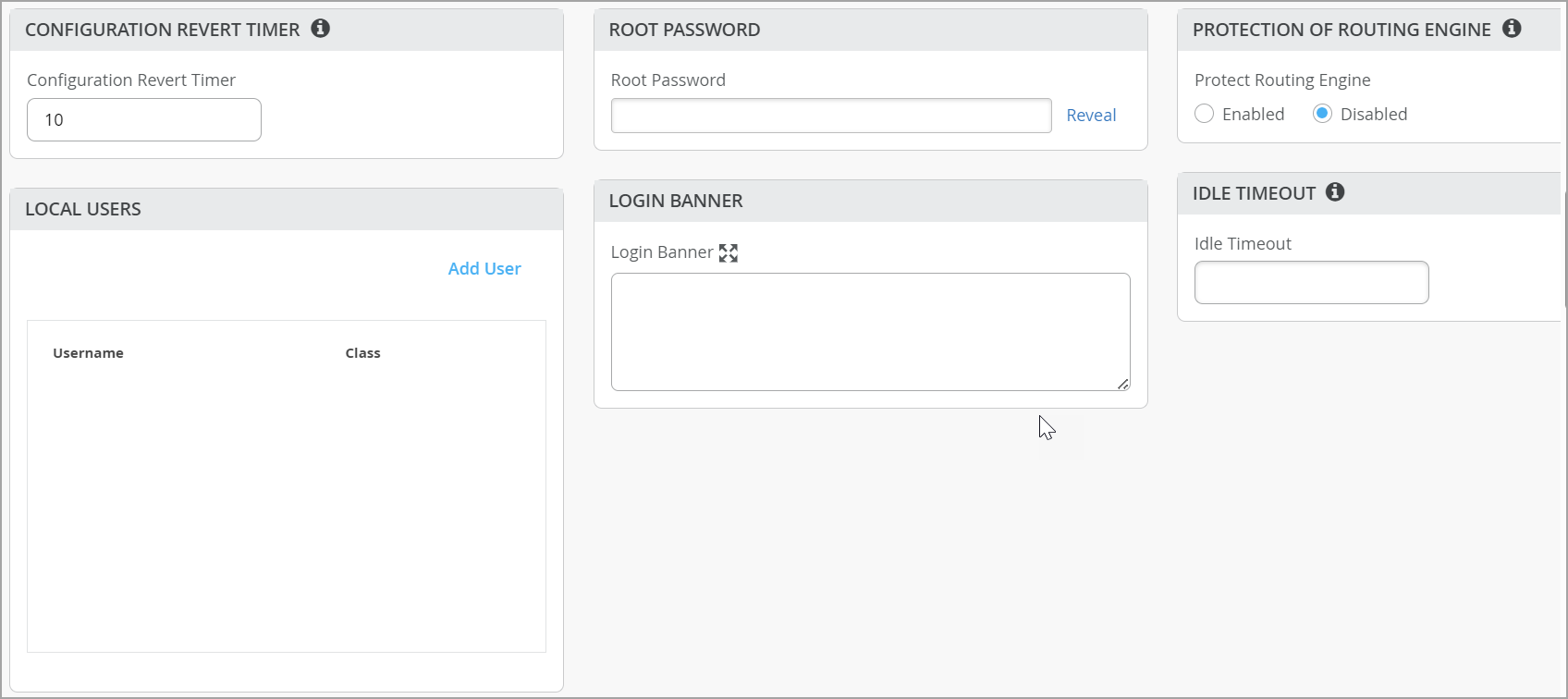
Management
Configure these options in the Management section of the Organization > Switch Templates page and the Site > Switch Configuration page.
| Option | Notes |
|---|---|
|
Configuration Revert Timer |
This feature helps restore connectivity between a switch and the Mist cloud if a configuration change causes the switch to lose connection. It automatically reverts the changes made by a user and reconnects to the cloud within a specified time duration. By default, this time duration is set to 10 minutes for EX Series switches. You can specify a different time duration. Range: 3 to 30 minutes. In case of a configuration revert event, you can check the switch events page to get specific insight into why the switch configuration was reverted. |
|
Root Password |
A plain-text password for the root-level user (whose username is root). |
|
Protection of Routing Engine |
Enable this feature to ensure that the Routing Engine accepts traffic only from trusted systems. This configuration creates a stateless firewall filter that discards all traffic destined for the Routing Engine, except packets from specified trusted sources. Protecting the Routing Engine involves filtering incoming traffic on the router’s lo0 interface. Enabling Protection of Routing Engine on Juniper Switches is suggested as the best practice. When Protection of Routing Engine is enabled, Mist by default ensures that the following services (if configured) are allowed to communicate with the switch: BGP, BFD, NTP, DNS, SNMP, TACACS, and RADIUS. If you need additional services that need access to the switch, you can use the Trusted Networks or Services section. If you want to set up access to the switch via ssh, select the ssh option under Trusted Services. If you need to allow switch to respond to pings, select the icmp option under Trusted Services. If you have other segments that you would like to reach the switch from, you can add them under Trusted Networks or Trusted IP/Port/Protocol. For more information, refer to Example: Configuring a Stateless Firewall Filter to Accept Traffic from Trusted Sources and Example: Configuring a Stateless Firewall Filter to Protect Against TCP and ICMP Floods. |
|
Local Users |
Create a local user account on the switch for device management purposes. To create a user account, click Add User and then define a username, login class (Operator, Read-only, Super User, or Unauthorized), and a password. |
|
Idle Timeout |
The maximum number of minutes that a remote shell session can be idle. When this limit is reached, users are logged out. (Valid Range: 1-60). |
|
Login Banner |
Enter text that you want users to see when they log in to the switch. Example: “Warning! This switch is managed by Juniper Mist. Do not make any CLI changes.” You can enter up to 2048 characters. |
|
DHCP Option 81 (For Dynamic DNS) |
Enable switches with DHCP option 81 support. When this option is enabled on a switch, the clients connected to that switch can send their fully qualified domain name (FQDN) to the DHCP server while requesting an IP address. This allows the DHCP server to update DNS records accordingly. You can enable the DHCP option 81 at the site level (Site > Switch Configuration) and device level (Switches > Switch Name) as well. |
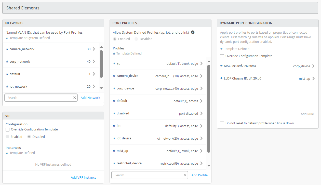
Shared Elements
Configure these options in the Shared Elements section of the Organization > Switch Templates page and the Site > Switch Configuration page.
| Option | Notes |
|---|---|
|
Networks |
Add or update VLANs, which you can then use in your port profiles. For each VLAN, enter the name, VLAN ID, and subnet. You can specify IPv4 or IPv6 address for the subnet. See the on-screen information for more tips. On this tile, you have an option to hide the networks that are not used in a user-defined port profiles or L3 sub-interfaces. This feature helps you quickly identify those networks that are in use and those that are not in use. |
|
Port Profiles |
Add or update port profiles. For help with the profile options, see the on-screen tips and Shared Elements—Port Profiles. On this tile, you have an option to hide the port profiles that are not used in any static or dynamic port configurations defined by users. This feature helps you quickly identify those port profiles that are in use and those that are not in use. |
|
Dynamic Port Configuration |
Dynamic port profiling uses a set of device properties of the connected client device to automatically associate pre-configured port and network settings to the interface. Dynamic port profile configuration involves the following two steps at a high level:
You can configure a dynamic port profile rules using the following parameters:
In this example, the port profile specified in the Apply Configuration Profile field will be assigned to a switch port enabled with dynamic configuration when it is connected to any devices with an LLDP system name that matches the parameters configured. 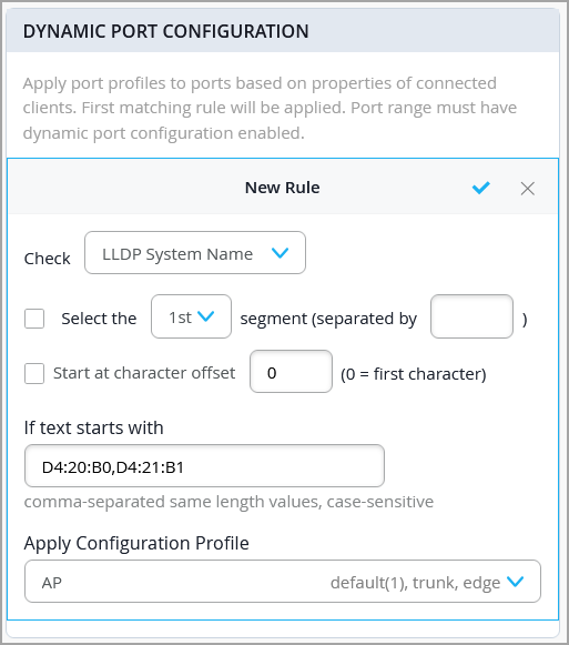 Note:
For more information, refer to Configure Dynamic Port Profile Assignment. |
|
VRF |
With VRF, you can divide an EX Series switch into multiple virtual routing instances, effectively isolating the traffic within the network. You can define a name for the VRF, specify the networks associated with it, and include any additional routes needed. You can specify IPv4 or IPv6 addresses for the additional route. Note:
|
Shared Elements—Port Profiles
In the Shared Elements section, you can configure port profiles. These options appear when you click Add Profile or when you click a profile to edit.
-
For general information about profiles, see Port Profiles.
-
If you're working at the site level, you might see asterisks (*) next to the port profile names. These port profiles were created in the switch template. If you click them, you'll see the settings in view-only mode. To make site-specific changes (affecting only this site and not the switch template itself), select Override Template Defined Profile and then edit the settings.
| Option | Notes |
|---|---|
| Name, Port Enabled, and Description |
Basic settings to identify and enable the port. |
| Mode |
|
| Port Network (Untagged/Native VLAN) | Specify the Port Network or native VLAN. |
| VoIP Network | Specify the VoIP Network (if applicable). |
| Trunk Networks | Specify a trunk network if you have chosen the mode Trunk. You can select all or specific networks. |
| Use dot1x authentication |
Select this option to enable IEEE 802.1X authentication for Port-Based Network Access Control. 802.1X authentication is supported on interfaces that are members of private VLANs (PVLANs). The following options are available if you enable dot1x authentication on a port:
You need to also do the following for dot1x authentication to work:
|
|
Speed |
Keep the default setting, Auto, or select a speed |
|
Duplex |
Keep the default setting, Auto, or select a Half or Full. |
| MAC Limit | Configure the maximum number of MAC addresses that can be
dynamically learned by an interface. When the interface exceeds the
configured MAC limit, it drops the frames. A MAC limit also results
in a log entry. The configured value remains active until it is
replaced or cleared, and persists through device reboot. The default value: 0 Supported range: 0 through 16383 |
| PoE |
Enable the port to support power over Ethernet (PoE). |
| Per VLAN STP |
Configure a switch with VLAN Spanning Tree Protocol (VSTP) or per-VLAN Spanning Tree. VSTP helps in preventing loops in Layer 2 networks on a per-VLAN basis. One Spanning Tree per VLAN enables fine grain load balancing. Mist recommends enabling this feature for other vendor’s devices (for example, Cisco) that operate per-VLAN Spanning Tree by default. This setting is available at the site and switch level as well. |
| STP Edge |
Configure the port as a Spanning Tree Protocol (STP) edge port, if you want to enable Bridge Protocol Data Unit (BPDU) guard on a port. STP Edge is enabled on ports to which clients that do not participate in STP are connected. This setting ensures that the port is treated as an edge port and guards against the reception of BPDUs. If you plug a non-edge device into a port configured with STP Edge, the port is disabled. In addition, the Switch Insights page generates a Port BPDU Blocked event. The Front Panel on the Switch Details will also display a BPDU Error for this port. You can clear the port of the BPDU error by selecting the port on the Front Panel and then clicking Clear BPDU Errors. You should not enable STP Edge on the Uplink port. You can also configure STP Edge at the switch level, from the Port Profile section on the switch details page. |
|
STP Point-to-Point |
This configuration changes the interface mode to point-to-point. Point-to-point links are dedicated links between two network nodes, or switches, that connect one port to another. |
|
STP No Root Port |
This configuration prevents the interface from becoming a root port. |
|
Block STP BPDUs |
Typically enabled on edge or access ports where BPDUs are not expected. When this option is enabled, the port is immediately shut down if a BPDU is received, helping to prevent potential loops or misconfigurations. If STP Edge is enabled, Block STP BPDUs is automatically disabled. However, BPDU Liveliness Check can still be configured. If Block STP BPDUs is enabled, both STP Edge and BPDU Liveliness Check are automatically disabled. |
| STP BPDU Liveliness Check | Typically enabled on uplink or trunk ports where BPDUs are expected. This feature monitors BPDU reception and blocks the port and raises an alarm if no BPDUs are received within 20 seconds, helping detect failures or misconfigurations quickly. |
| QoS |
Enable Quality of Service (QoS) for the port to prioritize latency-sensitive traffic, such as voice, over other traffic on a port. Note:
For optimal results, it's important to enable Quality of Service (QoS) for both the downstream (incoming) and upstream (outgoing) traffic. This ensures that the network can effectively prioritize and manage traffic in both directions, leading to improved performance and better overall quality of service. You have the option to override the QoS configuration on the WLAN settings page (Site > WLANs > WLAN name). To override the QoS configuration, select the Override QoS check box and choose a wireless access class. The downstream traffic (AP > client) gets marked with the override access class value specified. The override configuration doesn't support upstream traffic (client > AP). See also: QoS Configuration. |
| Storm Control |
Enable storm control to monitor traffic levels and automatically drop broadcast, multicast, and unknown unicast packets when the traffic exceeds a traffic level (specified in percentage). This specified traffic level is known as the storm control level. This feature actively prevents packet proliferation and maintains the performance of the LAN. When you enable Storm Control, you can also choose to exclude broadcast, multicast, and unknown unicast packets from monitoring. You can also configure a switch to automatically shut down a port when traffic exceeds the user-defined storm control threshold, by selecting the Shutdown Port check box under Action on Threshold. For more information, see Understanding Storm Control. |
| Persistent (Sticky) MAC Learning | Enable Persistent (Sticky) MAC to retain MAC addresses for trusted workstations and servers learned by the interface, even after a device restart. You can configure Sticky MAC for static wired clients. Sticky MAC is not intended for use on Juniper Mist AP interfaces, nor is it supported for trunk ports or those configured with 802.1X authentication. Used in conjunction with MAC Limits (explained above), Sticky MAC protects against Layer 2 denial-of-service (DoS) attacks, overflow attacks on the Ethernet switching table, and DHCP starvation attacks, while still allowing the interface to dynamically learn MAC addresses. In the Mist portal, the Insights page reports these events as MAC Limit Exceeded . You configure both Sticky MAC and MAC limits as part of the Port Profile for the switch. The general procedure is demonstrated in this video: Port profiles provide a convenient way to manually or automatically provision EX switch interfaces. Going into the EX4300, we'll first create VLANs. We'll make a camera network with VLAN ID 30 and an IoT network with VLAN ID 29. You can create as many networks as needed. You can create the profiles, for example, a camera, and map it to the camera network that we just created. Customize the settings as desired, such as PoE and STP. We'll repeat this process to create profiles for a corporate device enabling 802.1x authentication, an IoT device configured with PoE, and an access point configured as a trunk port. It's very simple to modify profiles to meet your specific requirements. Then we go into the port configuration section to associate the configurations with port profiles. Here we map ports 1 through 5 to be with an AP profile, ports 6 through 10 with a corporate device profile, ports 11 through 15 with IoT profiles, and ports 16 to 20 with the camera profile. This is how to create port profiles. We can also create port aggregation uplinks to be associated with the appropriate profiles. When you save all of your changes, this pushes the configuration to the particular switch. This covers how EX switches are manually provisioned with port profiles from the Juniper MIST Cloud. You must explicitly enable the Persistent (Sticky) MAC Learning option, located at the bottom of the Port Profile configuration block, to include Sticky MAC as part of the Port Profile that you associate with the interface. For MAC limits, the default value is 0 (unlimited, that is, disabled) but you can enable it by setting a value of up to 16383 unique MAC addresses allowed. To see in the Mist portal what value has been set for the MAC Limit or the MAC Count, select a switch from the Switches page and hover your mouse over a switch port. You can see which (port) Profile is applied to the interface, and by extension, know its Sticky MAC status. Figure 2: Port Details Showing Sticky MAC
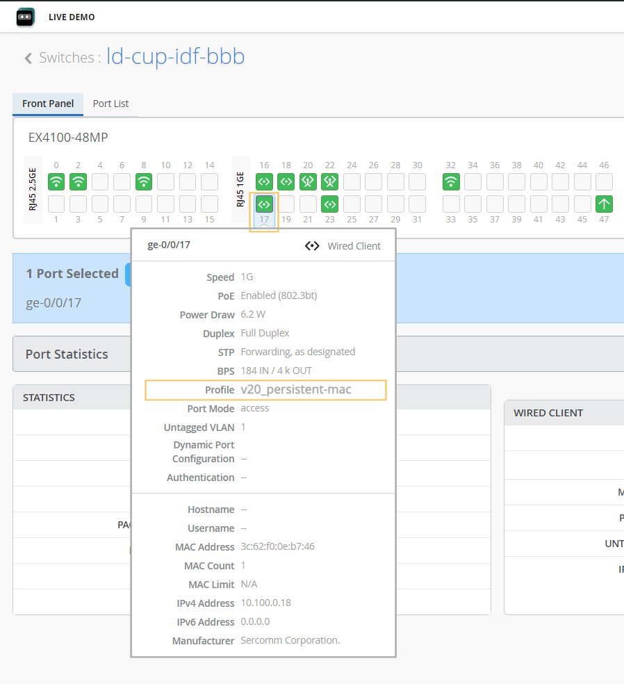
The configured MAC limit and number of MACs learned will appear after a few minutes, as dynamic learning on the interface progresses. In the Mist dashboard, only the maximum MAC address count is shown. However, you can see every MAC address a given interface has learned by opening a Remote Shell to the switch and running the following Junos CLI commands:
MAC count is a persistent value that remains until the MAC address is cleared (or until it is disabled in the Port Profile and then that configuration is pushed to the switch). To clear the MAC addresses on a given interface from the Mist dashboard, you need to be logged as Network Administrator or Super User. Then just select the port you want from the switch front panel (as shown in Figure 1) and click the Clear MAC [Dynamic/Persistent] button that appears. On the Switch Insights page, the event shows up as a MAC Limit Reset event. For more information on the front panel, see Switch Details. |
Select Switches Configuration
Create rules to apply configuration settings based on the name, role, or model of the switch.
Click a rule to edit it, or click Add Rule. Then complete each tabbed page. As you enter settings, click the checkmark at the top right to save your changes. You can also create a switch rule entry by cloning an existing rule. To do that, you just need to click the clone button and name the new rule.
The various tabs are described in separate tables below.
| Option | Notes |
|---|---|
|
Name |
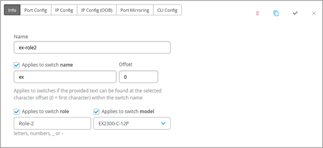
Enter a name to identify this rule. |
|
Applies to switch name |
Enable this option if you want this rule to apply to all switches that match the specified name. Then enter the text and the number of offset characters. For example, if you enter abc with an offset of 0, the rule applies to switches whose names start with abc. If the offset is 5, the rule ignores the first 5 characters of the switch name. |
|
Applies to switch role |
Enable this option if you want this rule to apply to all switches that have the same role. Enter the role by using lowercase letters, numbers, underscores (_), or dashes (-). |
|
Applies to switch model |
Enable this option if you want this rule to apply to all switches that have the same model. Then select the model. |
| Option | Notes |
|---|---|
| Configuration List | Click Add Port Configuration, or select a port configuration to edit. 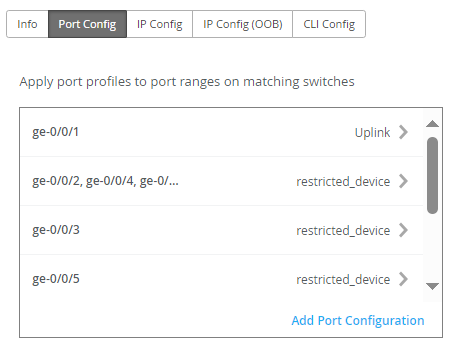 |
|
Port IDs |
Enter the port(s) to configure. |
| Configuration Profile | Select the configuration profile to apply to the specified
ports. Note:
If you want to configure switch ports with Q-in-Q tunneling, choose Q-in-Q from this drop-down list. For more information, refer to Configure Q-in-Q Tunneling on a Switch Port. |
|
Port Network (S-VLAN) |
Specify a service VLAN (S-VLAN) if the port is using Q-in-Q tunneling. S-VLAN is an external, additional VLAN tag used to extend Layer 2 Ethernet connections between customer sites. This is especially useful when customers have overlapping VLAN IDs. |
|
Speed |
Note:
Applicable only if you have selected Q-in-Q as the configuration profile. Keep the default setting, Auto, or select a speed. |
|
Duplex |
Note:
Applicable only if you have selected Q-in-Q as the configuration profile. Keep the default setting, Auto, or select a Half or Full. |
|
PoE |
Note:
Applicable only if you have selected Q-in-Q as the configuration profile. Enable the port to support power over Ethernet (PoE). |
|
MTU |
Note:
Applicable only if you have selected Q-in-Q as the configuration profile. Specify the media maximum transmission unit (MTU) for the port. Default: 1514. Range: 256 - 9216. The media maximum transmission unit (MTU) for an interface is the largest data unit that can be forwarded through that interface without fragmentation. |
|
Storm Control |
Note:
Applicable only if you have selected Q-in-Q as the configuration profile. Enable storm control to monitor traffic levels and automatically drop broadcast, multicast, and unknown unicast packets when the traffic exceeds a traffic level (specified in percentage). This specified traffic level is known as the storm control level. This feature actively prevents packet proliferation and maintains the performance of the LAN. When you enable Storm Control, you can also choose to exclude broadcast, multicast, and unknown unicast packets from monitoring. You can also configure a switch to automatically shut down a port when traffic exceeds the user-defined storm control threshold, by selecting the Shutdown Port check box under Action on Threshold. For more information, see Understanding Storm Control. |
| Description | Provide a description for the port. |
|
Enable Dynamic Configuration |
(This setting is not applicable if you have selected Q-in-Q as the configuration profile.) Note:
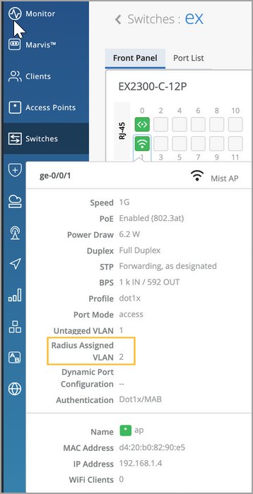
Ensure that you have created a restricted VLAN and network profile that can be assigned to unknown devices that are connected to a switch port enabled with dynamic port configuration but do not match the dynamic port assignment rules. This setting enables a switch port to work as a dynamic port, which uses the dynamic port assignment rules (described in the Dynamic Port Configuration row in Table 3). When a device is connected to a switch port enabled with dynamic port configuration, a port profile is dynamically assigned to it based on attributes of the connected device. If the device matches the attributes, Mist assigns a matching dynamic profile to the device. But if the device doesn't match the attributes, it is assigned a specified VLAN, ideally a restricted VLAN (port profile). In the following example, the port is enabled with dynamic port allocation and is assigned with a restricted VLAN. In this case, if the connected device doesn't match the dynamic profiling attributes, it will be placed into a restricted VLAN such as a non-routable VLAN or a guest VLAN. Interfaces enabled with Port Aggregation don't support dynamic port configuration. 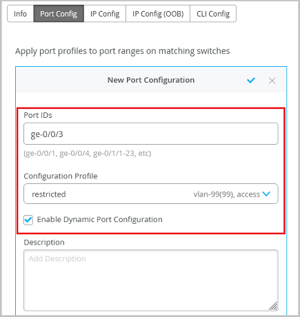 It takes a couple of minutes for a port profile to be applied a port after a client is recognized, and a couple of minutes after that for the port profile assignment status to appear on the Mist portal. In case of switch reboots or a mass link up or down event affecting all ports on a switch, it takes approximately 20 minutes for all the ports to be assigned to the right profile (assuming that dynamic port configuration is enabled on all the ports). Dynamic port configuration on a switch is meant for establishing connection to IoT devices, APs, and user port endpoints. Do not use it for creating connection between switches, switches and routers, and switches and firewalls. Also, you should not enable Dynamic Port Configuration on the uplink port. Note:
For more information, refer to Configure Dynamic Port Profile Assignment. |
|
Up/Down Port Alerts |
When you enable this feature, Juniper Mist monitors transitions between up and down states on these ports. If you enable this feature, also enable Critical Switch Port Up/Down on the Monitor > Alerts > Alerts Configuration page. |
|
Port Aggregation |
Note:
Not applicable if you have selected Q-in-Q as the configuration profile. When you enable this feature, the Ethernet interfaces specified are grouped to form a single link layer interface. This interface is also known as a link aggregation group (LAG) or bundle. The number of interfaces that you can group into a LAG and the total number of LAGs that a switch supports vary depending on switch model. You can use LAG with or without LACP enabled. If the device on the other end doesn't support LACP, you can disable LACP here. You can also specify the following:
For more information on how to configure link aggregation group (LAG) with Wired Assurance, watch the following video: |
|
Allow switch port operator to modify port profile |
When you enable this feature, users with the Switch Port Operator admin role can view and manage this configuration. |
| Option | Notes |
|---|---|
|
Network (VLAN) List |
Select a network for in-band management traffic. Or click Add Network and complete the New Network fields as described in the remaining rows of this table. 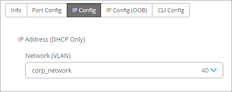 |
|
Name |
Enter a name to identify this network. |
|
VLAN ID |
Enter the VLAN ID from 1-4094, or enter a site variable to dynamically enter an ID. |
|
Subnet |
Enter the subnet or site variable. |
- Select Switches—IP Config (OOB) Tab
- Select Switches—Port Mirroring Tab
- Select Switches—CLI Config Tab
Select Switches—IP Config (OOB) Tab
Enable or disable Dedicated Management VRF (out of band). For all standalone devices or Virtual Chassis running Junos version 21.4 or later, this feature confines the management interface to non-default virtual routing and forwarding (VRF) instances. Management traffic no longer has to share a routing table with other control traffic or protocol traffic.
Select Switches—Port Mirroring Tab
This tab displays the list of port mirroring configurations already added. Click an entry to edit it. Or click Add Port Mirror to enable port mirroring. This feature allows you to dynamically apply port mirroring on switches based on the parameters such as the switch role, switch name, and switch model as specified in the rules. This feature is typically used for monitoring and troubleshooting. When port mirroring is enabled, the switch sends a copy of the network packet from the mirrored ports to the monitor port.
Mist supports both local and remote port mirroring. In local port mirroring, the source ports and the destination ports (monitor port) are located on the same network switch. In remote port mirroring, the source ports and destination ports are not on the same switch. In this case, the source port forwards the packet copy to the remote destination port through the connection achieved by the ports between the two switches.
The configuration options include the following:
-
Input—The source (an interface or network) of the traffic to be monitored. Along with the input, you can specify whether you want Mist to monitor the ingress traffic or the egress traffic for an interface. If you want both ingress and egress traffic to be monitored, add two input entries for the same interface - one with the ingress flag and the other with the egress flag.
-
Output—The destination to which you want to mirror the traffic. You can specify an interface, network, or an IP address (in case of a remote destination). You cannot specify the same interface or network in both the input and output fields.
The rules under Select Switches Configuration take precedence over the global Port Mirroring configuration. Also, if the global port mirroring is configured, it is displayed as the default rule in the Select Switches configuration section and is displayed as read-only. You can edit it at the global level.
Select Switches—CLI Config Tab
Enter additional CLI commands, as needed.
Switch Policy Labels, GBP Tags, and Switch Policies
Use this section to create Access Control Lists (ACLs) (also known as firewall filters) and Group-Based Policies (GBP).
-
Source/Destination labels—Create labels to identify the source/destination IP addresses for Access Control List (ACL) policies (RADIUS-based firewall filters). For more information, see Firewall Filters.
-
GBP tags—(For Campus Fabric IP-Clos deployments) Create tags for Group-Based Policies (GBP), which leverage VXLAN technology. GBP simplifies configuration and provides endpoint access control across your campus. For more information, see Group-Based Policies.