ON THIS PAGE
Configuring a NorthStar Cluster for High Availability
Before You Begin
Configuring a NorthStar application cluster for high availability (HA) is an optional process. This topic describes the steps for configuring, testing, deploying, and maintaining an HA cluster. If you are not planning to use the NorthStar application HA feature, you can skip this topic.
See High Availability Overview in the NorthStar Controller User Guide for overview information about HA. For information about analytics HA, see Installing Data Collectors for Analytics.
Throughout your use of NorthStar Controller HA, be aware that you must replicate any changes you make to northstar.cfg to all cluster nodes so the configuration is uniform across the cluster. NorthStar CLI configuration changes, on the other hand, are replicated across the cluster nodes automatically.
Download the NorthStar Controller and install it on each server that will be part of the cluster. Each server must be completely enabled as a single node implementation before it can become part of a cluster.
This includes:
Creating passwords
License verification steps
Connecting to the network for various protocol establishments such as PCEP or BGP-LS
Note:All of the servers must be configured with the same database and RabbitMQ passwords.
All server time must be synchronized by NTP using the following procedure:
Install NTP.
yum -y install ntp
Specify the preferred NTP server in ntp.conf.
Verify the configuration.
ntpq -p
Note:All cluster nodes must have the same time zone and system time settings. This is important to prevent inconsistencies in the database storage of SNMP and LDP task collection delta values.
Run the net_setup.py utility to complete the required elements of the host and JunosVM configurations. Keep that configuration information available.
Note:If you are using an OpenStack environment, you will have one JunosVM that corresponds to each NorthStar Controller VM.
Know the virtual IPv4 address you want to use for Java Planner client and web UI access to NorthStar Controller (required). This VIP address is configured for the router-facing network for single interface configurations, and for the user-facing network for dual interface configurations. This address is always associated with the active node, even if failover causes the active node to change.
A virtual IP (VIP) is required when setting up a NorthStar cluster. Ensure that all servers that will be in the cluster are part of the same subnet as the VIP.
Decide on the priority that each node will have for active node candidacy upon failover. The default value for all nodes is 0, the highest priority. If you want all nodes to have equal priority for becoming the active node, you can just accept the default value for all nodes. If you want to rank the nodes in terms of their active node candidacy, you can change the priority values accordingly—the lower the number, the higher the priority.
Set Up SSH Keys
Set up SSH keys between the selected node and each of the other nodes in the cluster, and each JunosVM.
Access the HA Setup Main Menu
- Type E and press Enter to display the HA Setup main menu.
Figure 1 shows the top portion of the HA Setup main menu in which the current configuration is listed. It includes the five supported interfaces for each node, the VIP addresses, and the ping interval and timeout values. In this figure, only the first of the nodes is included, but you would see the corresponding information for all three of the nodes in the cluster configuration template. HA functionality requires an odd number of nodes in a cluster, and a minimum of three.
Note:If you have a cRPD installation, the JunosVM information is not displayed as it is not applicable.
Figure 1: HA Setup Main Menu, Top Portion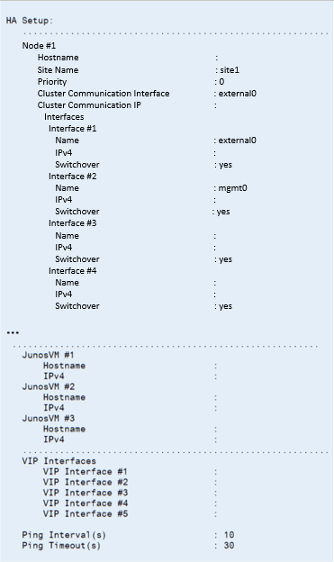 Note:
Note:If you are configuring a cluster for the first time, the IP addresses are blank and other fields contain default values. If you are modifying an existing configuration, the current cluster configuration is displayed, and you have the opportunity to change the values.
Note:If the servers are located in geodiverse locations, you can use Site Name to indicate which servers are in the same or different geographical locations.
Figure 2 shows the lower portion of the HA Setup main menu. To complete the configuration, you type the number or letter of an option and provide the requested information. After each option is complete, you are returned to the HA Setup main menu so you can select another option.
Figure 2: HA Setup Main Menu, Lower Portion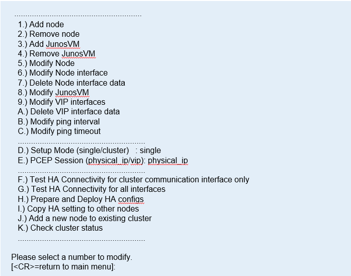 Note:
Note:If you have a cRPD installation, options 3, 4, and 8 are not displayed as they are not applicable. The remaining options are not renumbered.
Configure the Three Default Nodes and Their Interfaces
The HA Setup main menu initially offers three nodes for configuration because a cluster must have a minimum of three nodes. You can add more nodes as needed.
For each node, the menu offers five interfaces. Configure as many of those as you need.
Configure the JunosVM for Each Node
To complete the node-specific setup, configure the JunosVM for each node in the cluster.
- When prompted, enter the node number, the JunosVM hostname,
and the JunosVM IPv4 address, pressing Enter between entries.
Figure 3 shows these JunosVM setup fields.
Figure 3: Node 1 JunosVM Setup Fields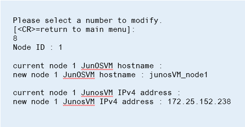
When finished, you are returned to the HA Setup main menu.
(Optional) Add More Nodes to the Cluster
If you want to add additional nodes, type 1 and press Enter. Then configure the node and the node’s JunosVM using the same procedures previously described. Repeat the procedures for each additional node.
HA functionality requires an odd number of nodes and a minimum of three nodes per cluster.
The following example shows adding an additional node, node #4, with two interfaces.
Please select a number to modify.
[<CR>=return to main menu]:
1
New Node ID : 4

current node 4 Node hostname (without domain name) :
new node 4 Node hostname (without domain name) : node-4

current node 4 Site Name : site1
new node 4 Site Name : site1

current node 4 Node priority : 0
new node 4 Node priority : 40

current node 4 Node cluster communication interface : external0
new node 4 Node cluster communication interface : external0

current node 4 Node cluster communication IPv4 address :
new node 4 Node cluster communication IPv4 address : 10.25.153.12


current node 4 Node interface #2 name : mgmt0
new node 4 Node interface #2 name : external1

current node 4 Node interface #2 IPv4 address :
new node 4 Node interface #2 IPv4 address : 10.100.1.7

current node 4 Node interface #2 switchover (yes/no) : yes
new node 4 Node interface #2 switchover (yes/no) :

current node 4 Node interface #3 name :
new node 4 Node interface #3 name :

current node 4 Node interface #3 IPv4 address :
new node 4 Node interface #3 IPv4 address :

current node 4 Node interface #3 switchover (yes/no) : yes
new node 4 Node interface #3 switchover (yes/no) :

current node 4 Node interface #4 name :
new node 4 Node interface #4 name :

current node 4 Node interface #4 IPv4 address :
new node 4 Node interface #4 IPv4 address :

current node 4 Node interface #4 switchover (yes/no) : yes
new node 4 Node interface #4 switchover (yes/no) :

current node 4 Node interface #5 name :
new node 4 Node interface #5 name :

current node 4 Node interface #5 IPv4 address :
new node 4 Node interface #5 IPv4 address :

current node 4 Node interface #5 switchover (yes/no) : yes
new node 4 Node interface #5 switchover (yes/no) :
The following example shows configuring the JunosVM that corresponds to node #4.
Please select a number to modify.
[<CR>=return to main menu]
3
New JunosVM ID : 4
current junosvm 4 JunOSVM hostname :
new junosvm 4 JunOSVM hostname : junosvm-4

current junosvm 4 JunOSVM IPv4 address :
new junosvm 4 JunOSVM IPv4 address : 10.25.153.13
Configure Cluster Settings
The remaining settings apply to the cluster as a whole.
Test and Deploy the HA Configuration
You can test and deploy the HA configuration from within the HA Setup main menu.
- Set the web UI admin password using either the web UI
or net_setup.
For the web UI method, use the external IP address that was provided to you when you installed the NorthStar application. Type that address into the address bar of your browser (for example, https://10.0.1.29:8443). A window is displayed requesting the confirmation code in your license file (the characters after S-NS-SDN=), and the password you wish to use. See Figure 4.
Figure 4: Web UI Method for Setting the Web UI Password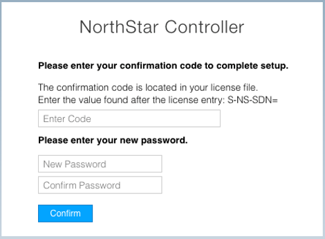
For the net_setup method, select D from the net_setup Main Menu (Maintenance & Troubleshooting), and then 3 from the Maintenance & Troubleshooting menu (Change UI Admin Password).
Main Menu:
    .............................................
    A.) Host Setting
    .............................................
    B.) JunosVM Setting
    .............................................
    C.) Check Network Setting
    .............................................
    D.) Maintenance & Troubleshooting
    .............................................
    E.) HA Setting
    .............................................
    F.) Collect Trace/Log
    .............................................
    G.) Analytics Data Collector Setting
       (External standalone/cluster analytics server)
    .............................................
    H.) Setup SSH Key for external JunosVM  setup
    .............................................
    I.) Internal Analytics Setting (HA)
    .............................................
    X.) Exit
    .............................................
Please select a letter to execute.
D


Maintenance & Troubleshooting:
   ..................................................
   1.) Backup JunosVM Configuration
   2.) Restore JunosVM Configuration
   3.) Change UI Admin Password
   4.) Change Database Password
   5.) Change MQ Password
   6.) Change Host Root Password
   7.) Change JunosVM root and northstar User Password
   8.) Initialize all credentials ( 3,4,5,6,7 included)
   ..................................................

Please select a number to modify.

[<CR>=return to main menu]:
3
Type Y to confirm you wish to change the UI Admin password, and enter the new password when prompted.
Change UI Admin Password
Are you sure you want to change the UI Admin password? (Y/N) y

Please enter new UI Admin password :
Please confirm new UI Admin password :
Changing UI Admin password ...
UI Admin password has been changed successfully
Replace a Failed Node if Necessary
On the HA Setup menu, options I and J can be used when physically replacing a failed node. They allow you to replace a node without having to redeploy the entire cluster which would wipe out all the data in the database.
While a node is being replaced in a three-node cluster, HA is not guaranteed.
Configure Fast Failure Detection Between JunosVM and PCC
You can use Bidirectional Forward Detection (BFD) in deploying the NorthStar application to provide faster failure detection as compared to BGP or IGP keepalive and hold timers. The BFD feature is supported in PCC and JunosVM.
To utilize this feature, configure bfd-liveness-detection minimum-interval milliseconds on the PCC, and mirror this configuration on the JunosVM. We recommend a value of 1000 ms or higher for each cluster node. Ultimately, the appropriate BFD value depends on your requirements and environment.