Connect the EX4000 to Power
Connect Earth Ground to an EX4000 Switch
To ensure proper operation and to meet electromagnetic interference (EMI) requirements, you must connect EX4000 switch models to earth ground before you connect power to the switch. You must use the protective earthing terminal on the switch chassis to connect the switch to earth ground.
You must install the EX4000 switches in a restricted-access location and ensure that the chassis is always properly grounded. EX4000 switches have a two-hole protective grounding terminal on the rear panel of the chassis. Under all circumstances, use this grounding connection to ground the chassis. For AC-powered systems, you must also use the grounding wire in the AC power cord along with the two-hole grounding lug connection. This tested system meets or exceeds all applicable EMC regulatory requirements with the two-hole protective grounding terminal.
Ensure that a licensed electrician has attached the appropriate grounding lug to the grounding cable that you supply. Using a grounding cable with an incorrectly attached lug can damage the switch.
Before you connect earth ground to a EX4000 switch, ensure that you have parts and tools listed in Table 1 available:
|
Item |
Switch Model |
Description |
|---|---|---|
|
Earthing terminal location |
EX4000 switches |
Rear panel of the chassis |
|
Grounding cable requirements |
EX4000 switches |
Grounding cable (Yellow green): 6 AWG (13 mm²), minimum 90° C copper stranded wire, or as permitted by the local code—not provided.
|
|
Grounding lug specifications |
EX4000 switches |
Panduit LCD6-14AF or equivalent—not provided |
|
Screws to secure the grounding lug |
EX4000 switches |
Two M5 X 10 mm screws with washer—seperately orderable |
|
Tools required |
EX4000 switches |
Number 2 Phillips (+) screwdriver—not provided Electrostatic discharge (ESD) grounding strap—not provided |
-
Grounding Lug - Customers can order Ground lug kit, JNP-GL-2H6-M5-RA (or equivalent lug and screws)
-
The ground lug kit JNP-GL-2H6-M5-RA consists of:
-
One panduit lug LCD6-14AF-L
-
Two stainless steel screw with washer, M5 x 9.5
-
To ground the EX4000 switch to a proper ground reference:
-
Place the grounding lug attached to the grounding cable over the protective
earthing terminal on the rear panel.
Figure 1: Connect a Grounding Cable to an EX4000-8P Switch
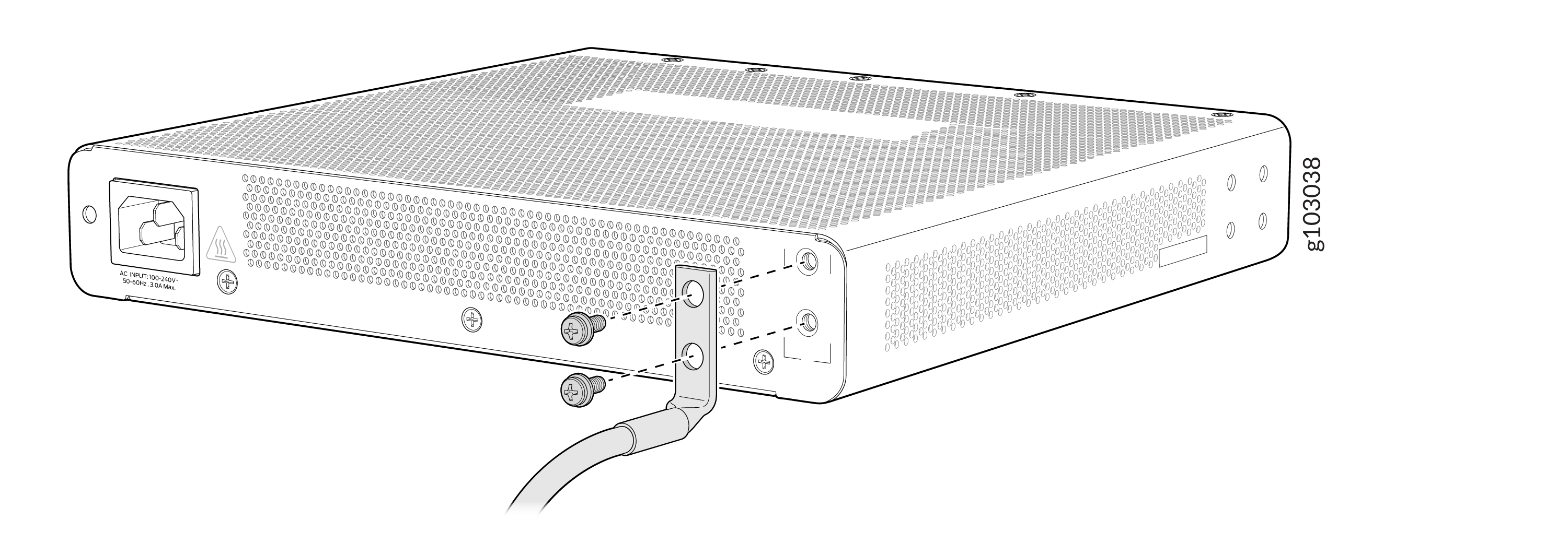 Figure 2: Connect a Grounding Cable to an EX4000-12T Switch
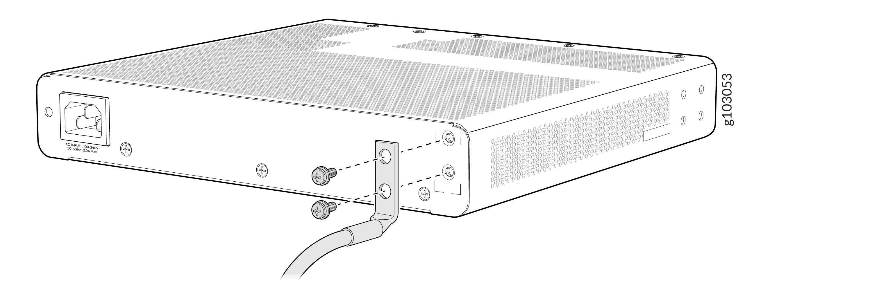 Figure 3: Connect a Grounding Cable to an EX4000-12P or EX4000-12MP Switch
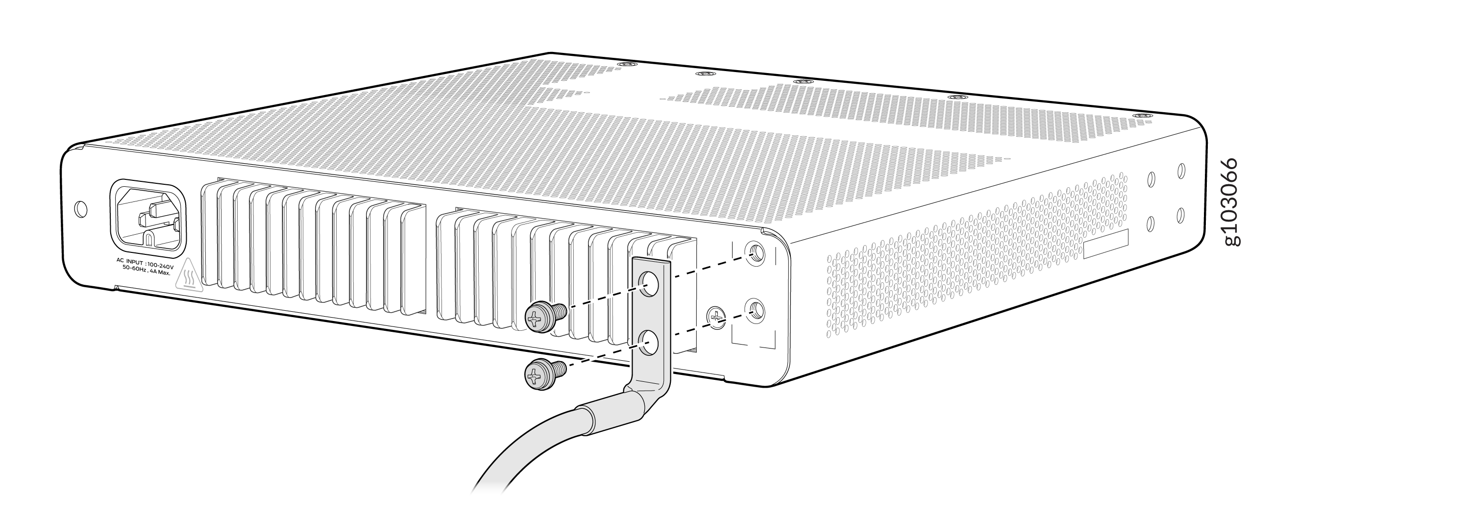 Figure 4: Connect a Grounding Cable to an EX4000-24P Switch
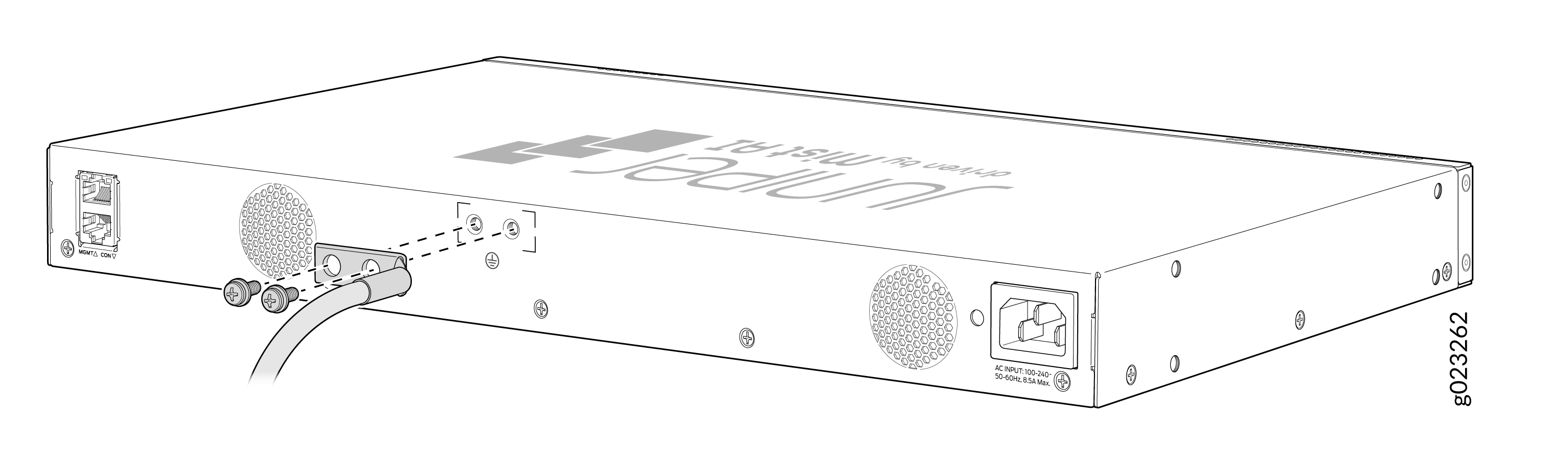 Figure 5: Connect a Grounding Cable to an EX4000-24T Switch
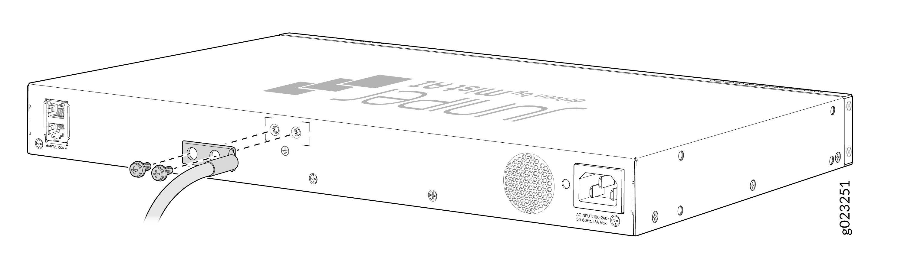 Figure 6: Connect a Grounding Cable to an EX4000-24MP Switch
 Figure 7: Connect a Grounding Cable to an EX4000-48P Switch
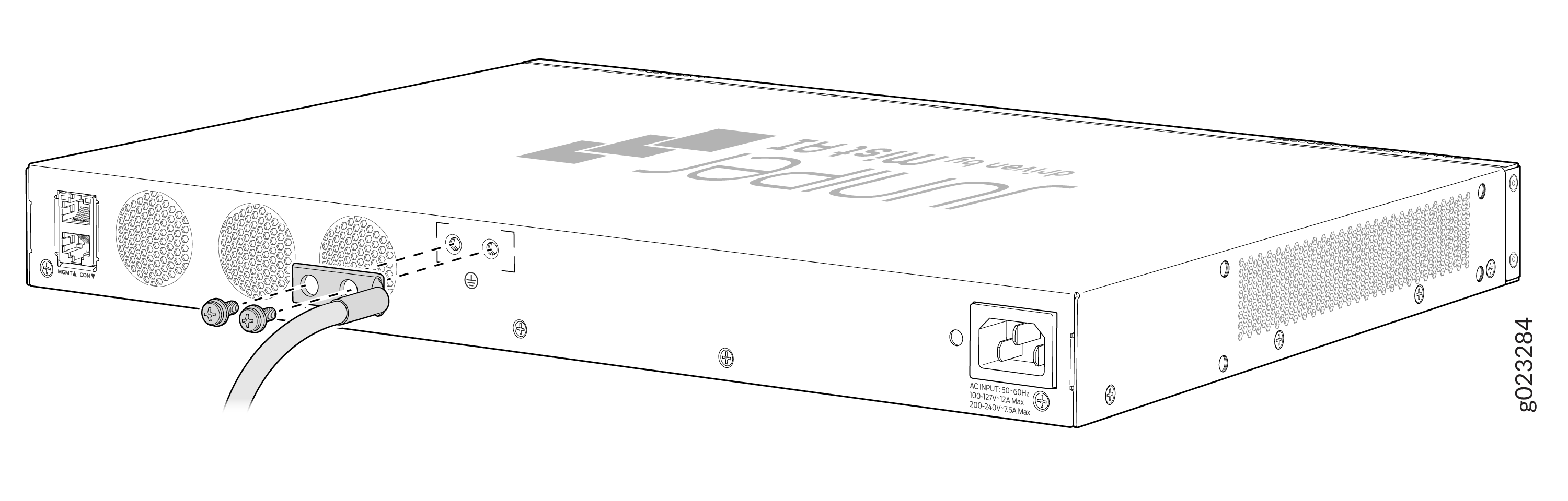 Figure 8: Connect a Grounding Cable to an EX4000-48T Switch
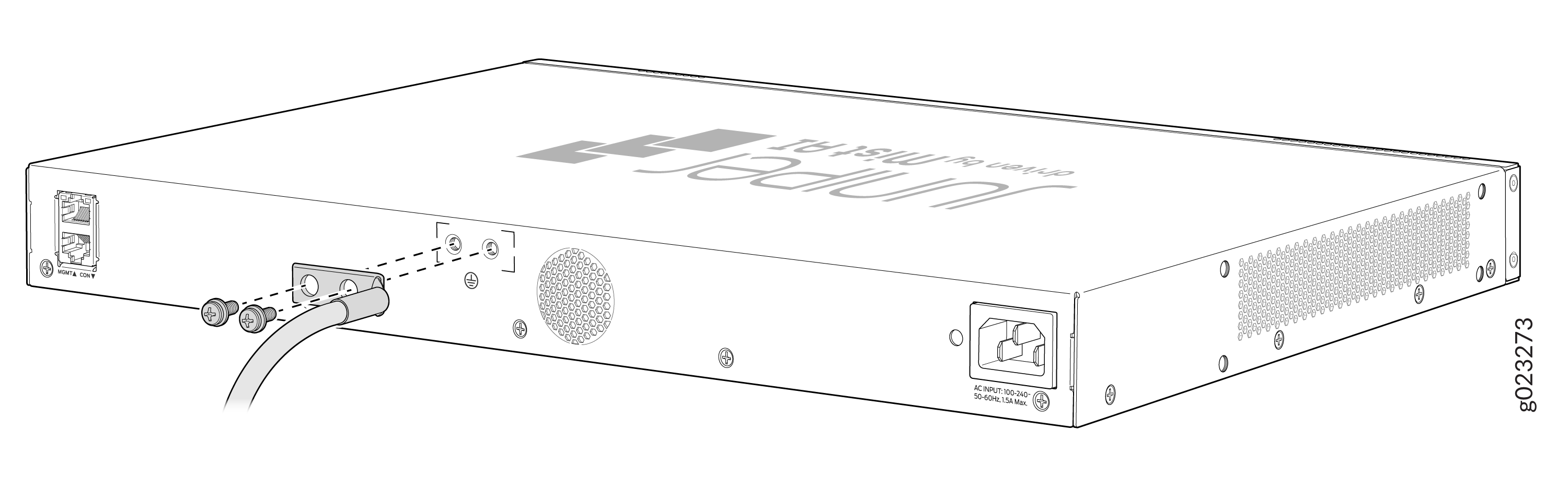 Figure 9: Connect a Grounding Cable to an EX4000-48MP Switch
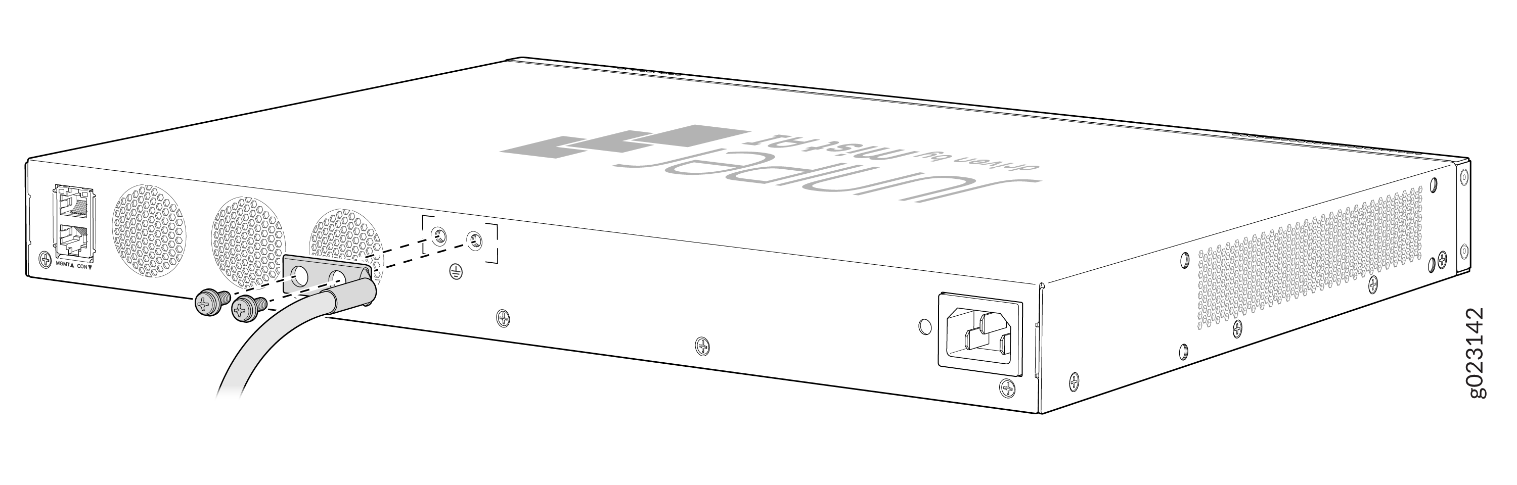
Connect AC Power to an EX4000 Switch
Before you connect AC power, ensure that you have the following parts and tools available:
-
A power cord appropriate for your geographical location—provided
Ensure that you have connected the device chassis to earth ground. The AC power cords also provide additional grounding when you connect the power supply in the switch to a grounded AC power outlet by using the AC power cord appropriate for your geographical location (see AC Power Cord Specifications).
For installations that require a separate grounding conductor to the chassis, have a licensed electrician complete this connection before you connect the switch to power. For instructions on connecting earth ground, see Connect Earth Ground to an EX4000 Switch.
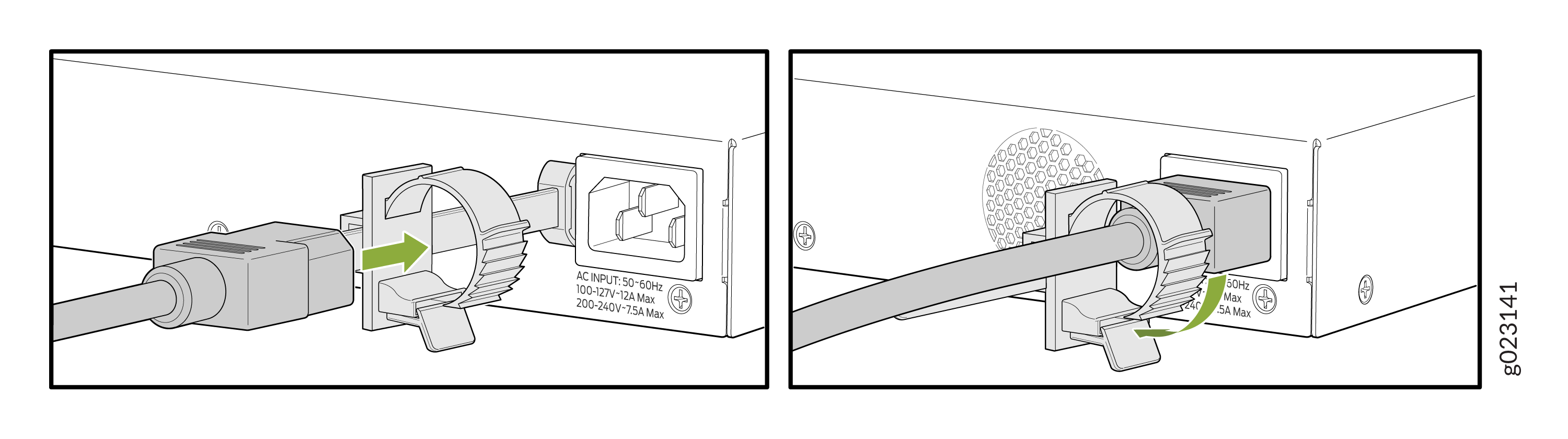
To connect AC power to the switch:
-
On the rear panel of the switch, insert the power cord retainer into the
power cord retainer slot.
Figure 10: Insert the power cord retainer into the EX4000-8P switch
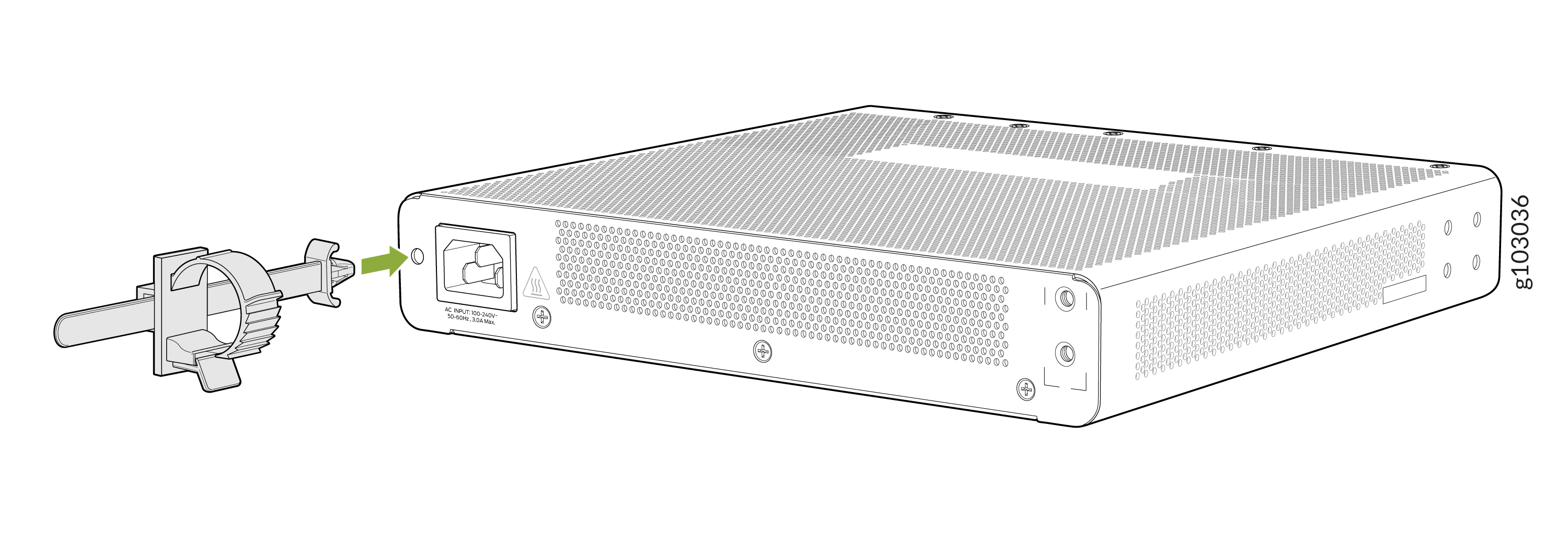 Figure 11: Insert the power cord retainer into the EX4000-12T switch
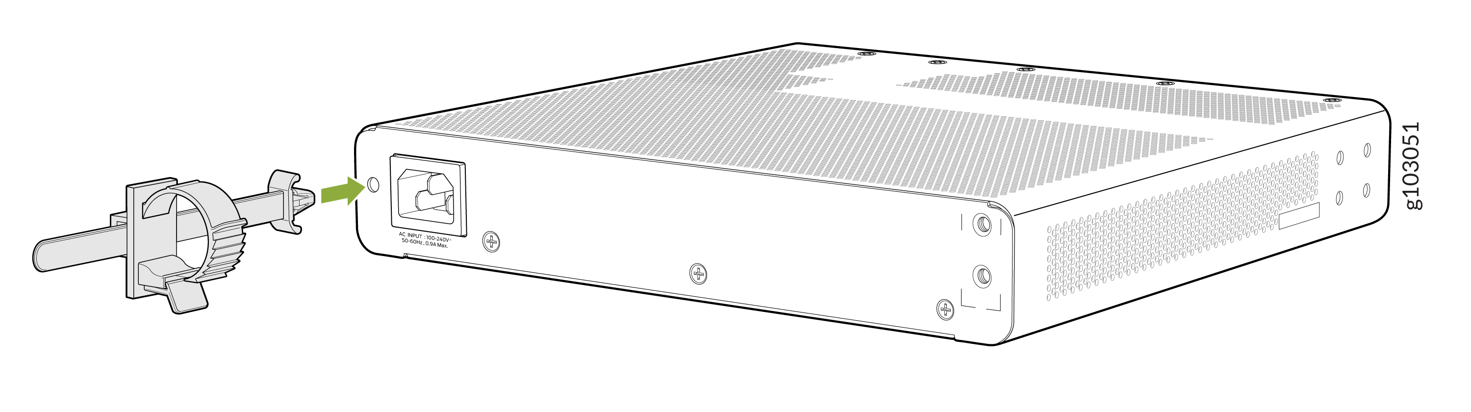 Figure 12: Insert the power cord retainer into the EX4000-12P or EX4000-12MP switch
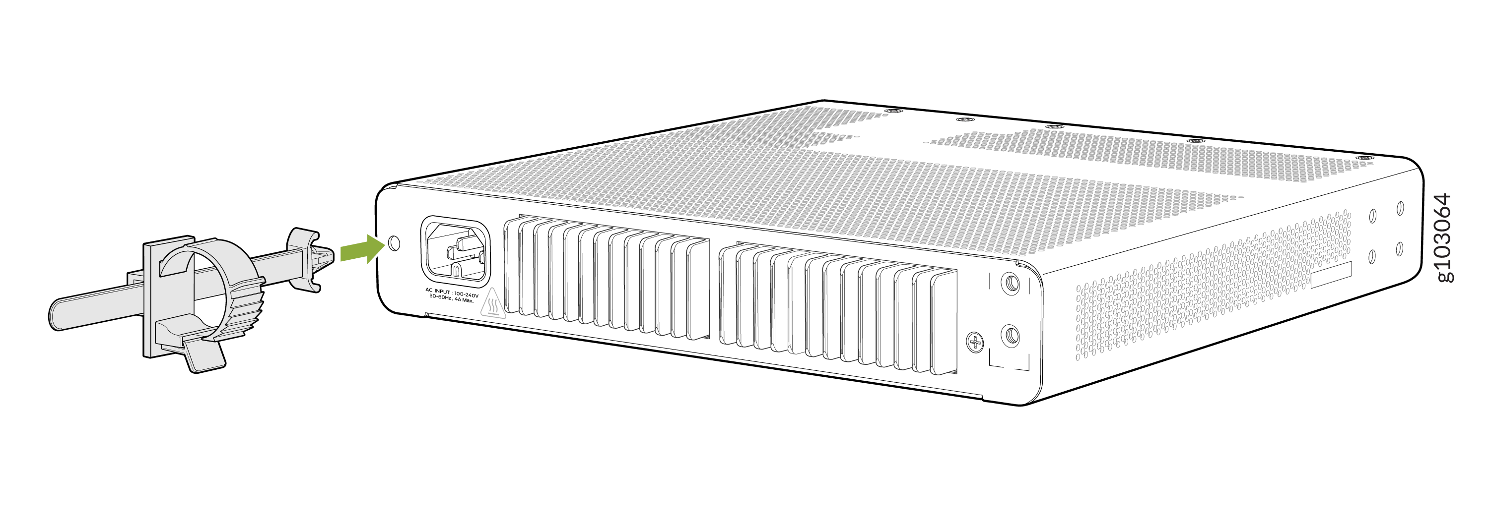 Figure 13: Insert the power cord retainer into the EX4000-24P, EX4000-24T, or EX4000-24MP switch
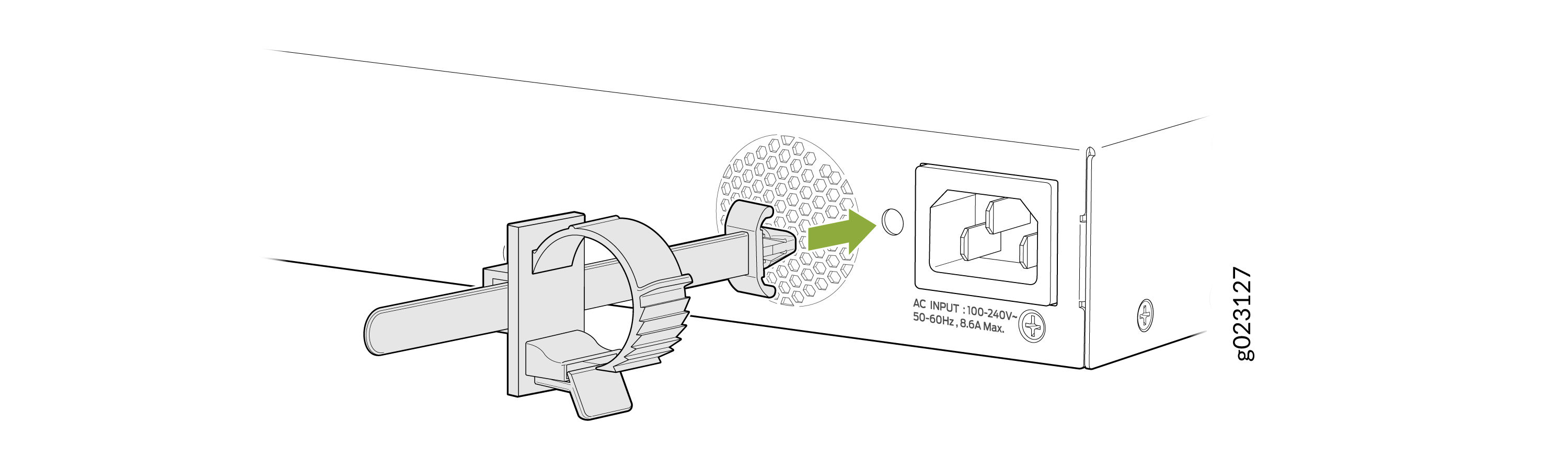 Figure 14: Insert the power cord retainer into the EX4000-48P, EX4000-48T, or EX4000-48MP switch
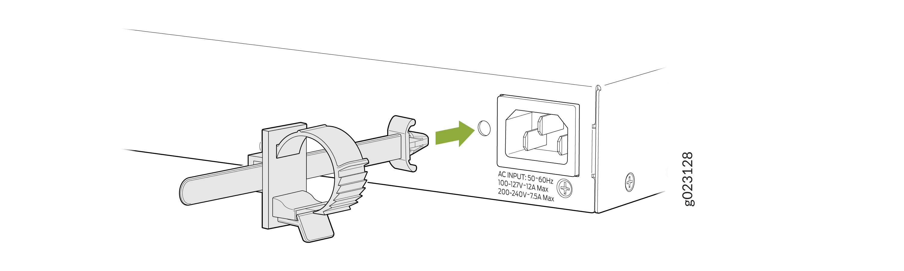
-
On the rear panel of the switch, insert the power cord plug into the power
input terminal. Press the tab on the power cord retainer loop until the loop
is snug against the base of the coupler.
Figure 15: Insert the AC power cord to the EX4000-8P switch
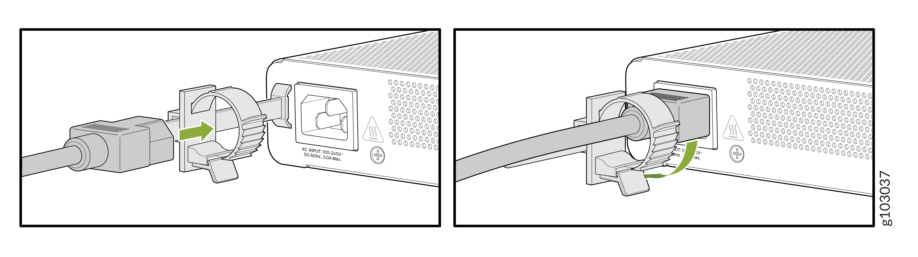 Figure 16: Insert the AC power cord to the EX4000-12T switch
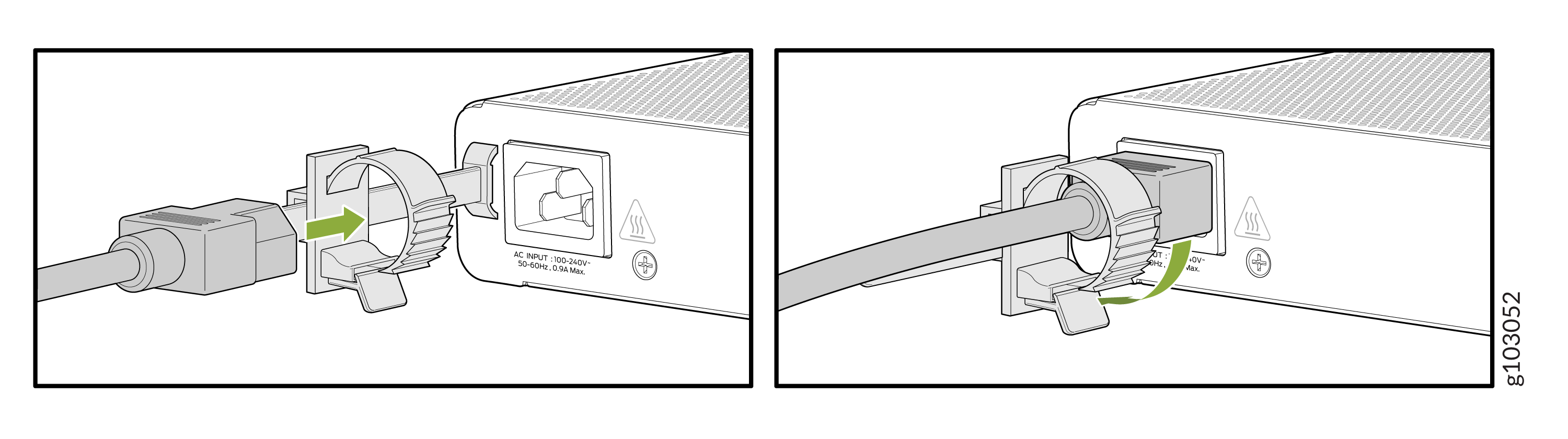 Figure 17: Insert the AC power cord to the EX4000-12P or EX4000-12MP switch
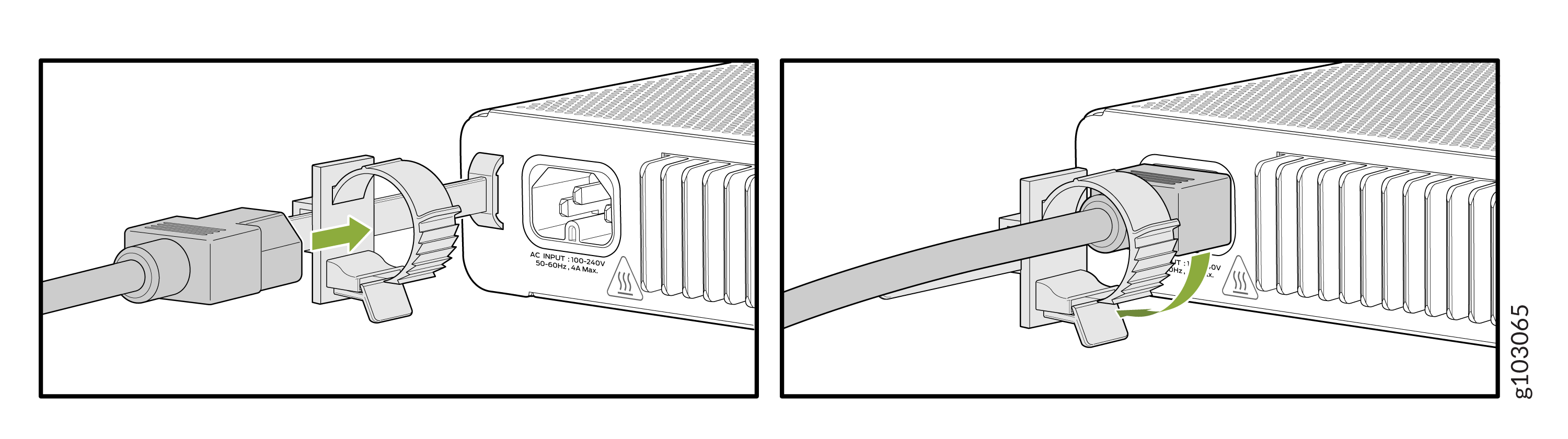 Figure 18: Insert the AC power cord to the EX4000-24P, EX4000-24T, or EX4000-24MP switch
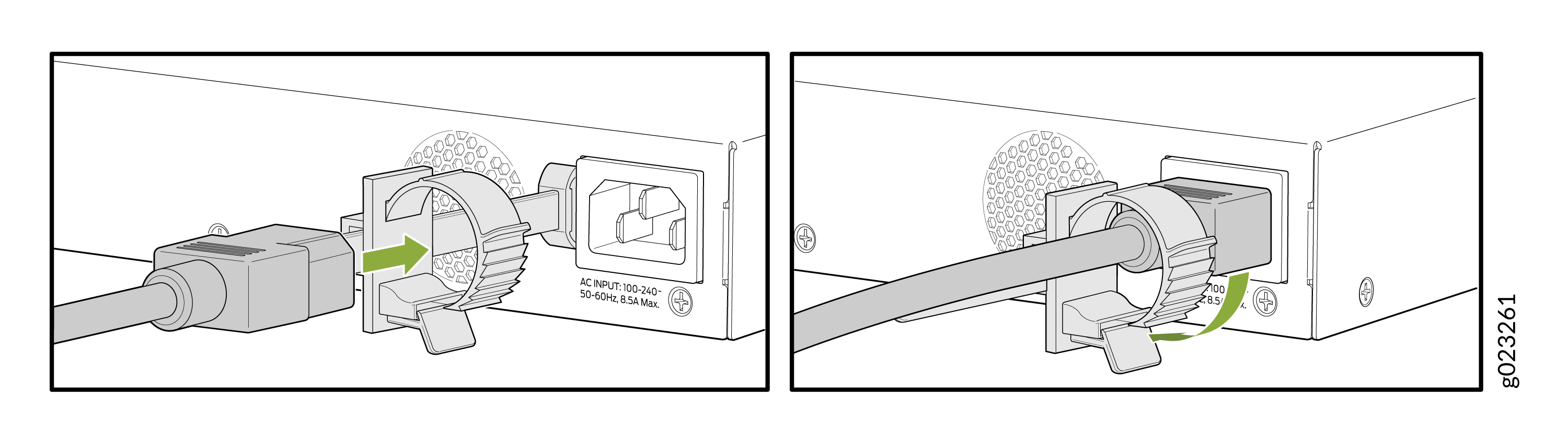 Figure 19: Insert the AC power cord to the EX4000-48P switch
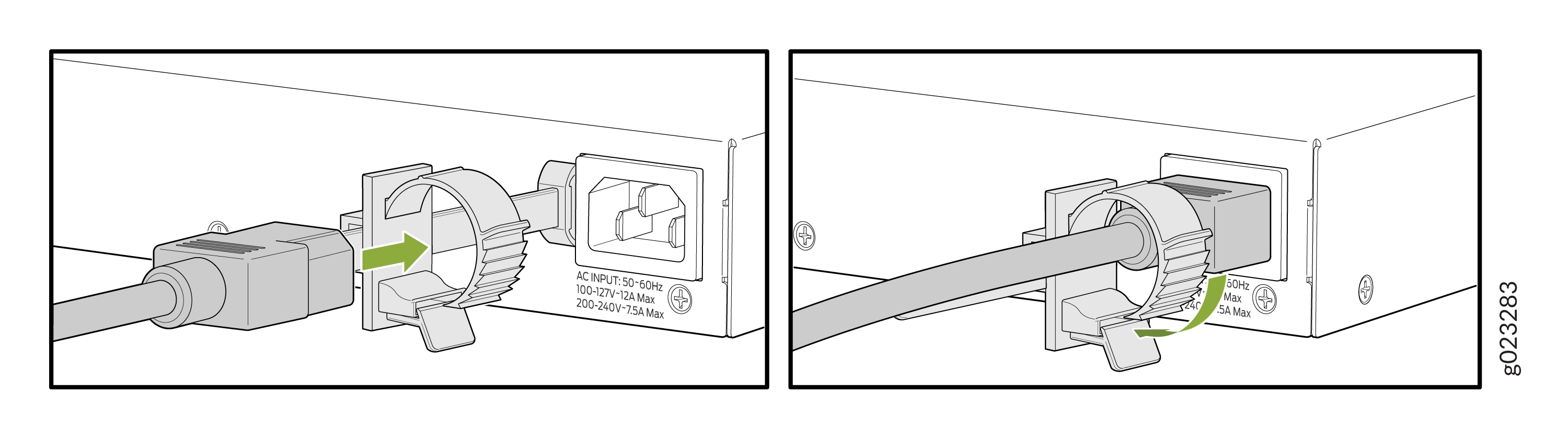 Figure 20: Insert the AC power cord to the EX4000-48T switch
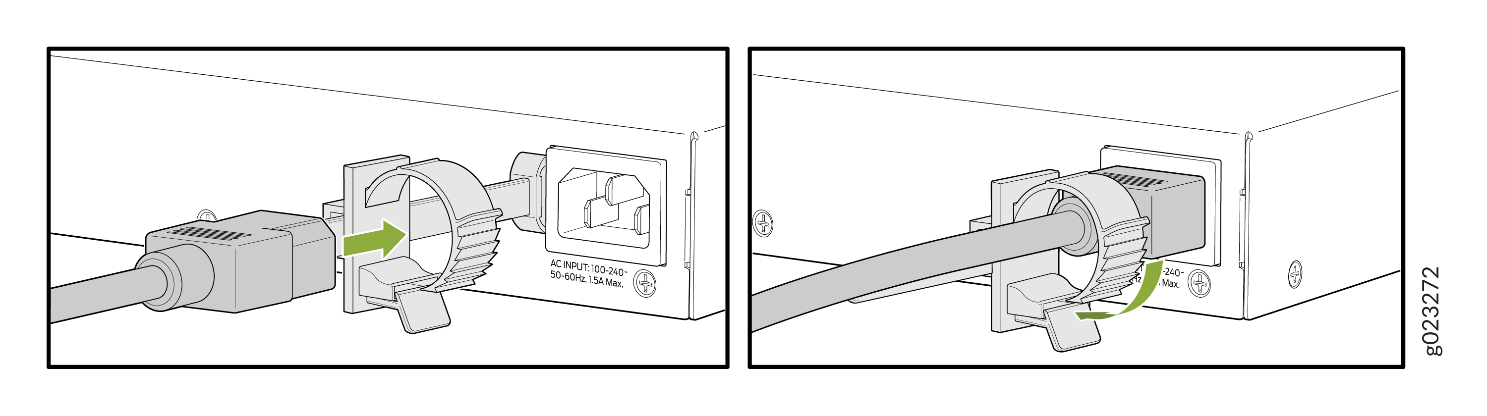 Figure 21: Insert the AC power cord to the EX4000-48MP switch