Fast Track to Rack Installation and Power
This procedure guides you through the simplest steps for the most common installation to get your EX4000 switch in a rack and connect it to power. Have more complex installation needs? See Install the EX4000 Switch
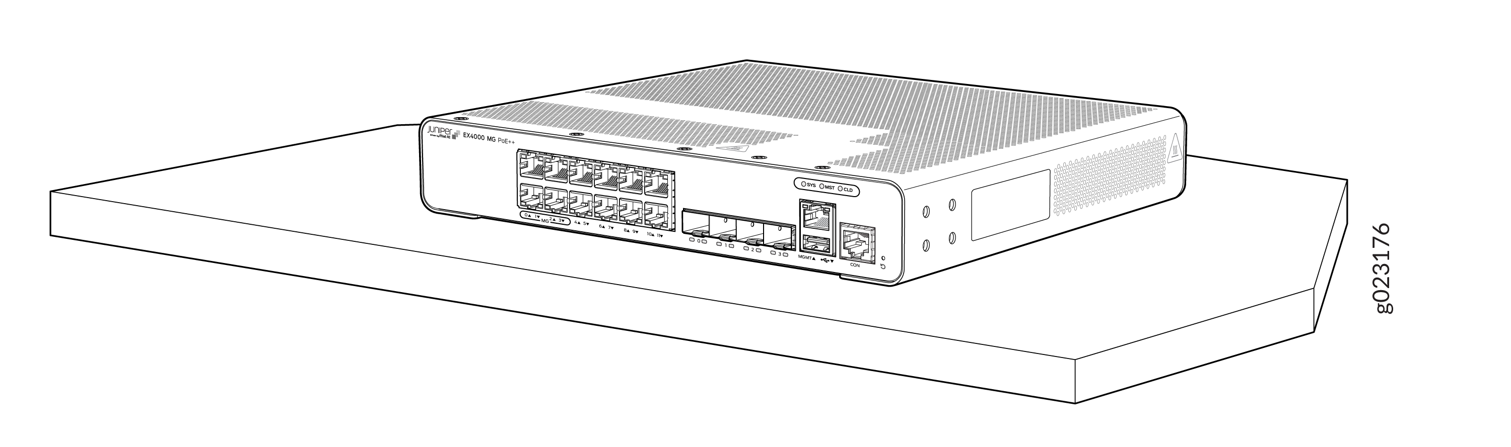
Install the EX4000-8P, EX4000-12T, EX4000-12P, or EX4000-12MP on a Desk
On-the-desk mounting is the default mounting option for the EX4000-8P, EX4000-12T, EX4000-12P, or EX4000-12MP switches. We'll walk you through how to install the switch on a desk. For the rest of the mounting options refer Install the EX4000 Switch.
What's in the Box?
-
The EX4000-8P, EX4000-12T, EX4000-12P, or EX4000-12MP switch
-
One AC power cord appropriate for your geographical location
-
Power cord retainer
-
Preinstalled dust covers for SFP ports
-
Documentation roadmap card
Do not block the vents on top of the switch to prevent the switch chassis from overheating.
Ensure that the desktop or any other level surface is stable and securely supported.
Before you install, review the following:
-
Place the switch on a flat, stable surface.
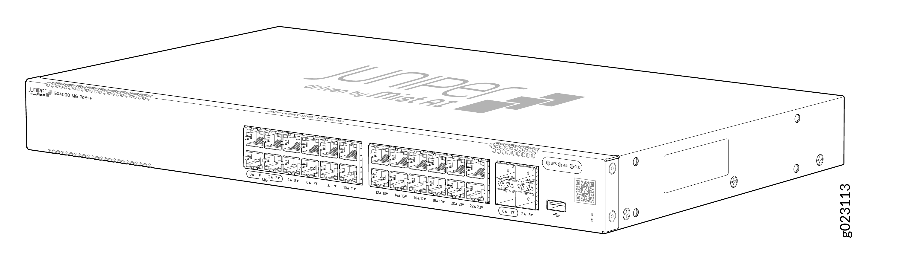
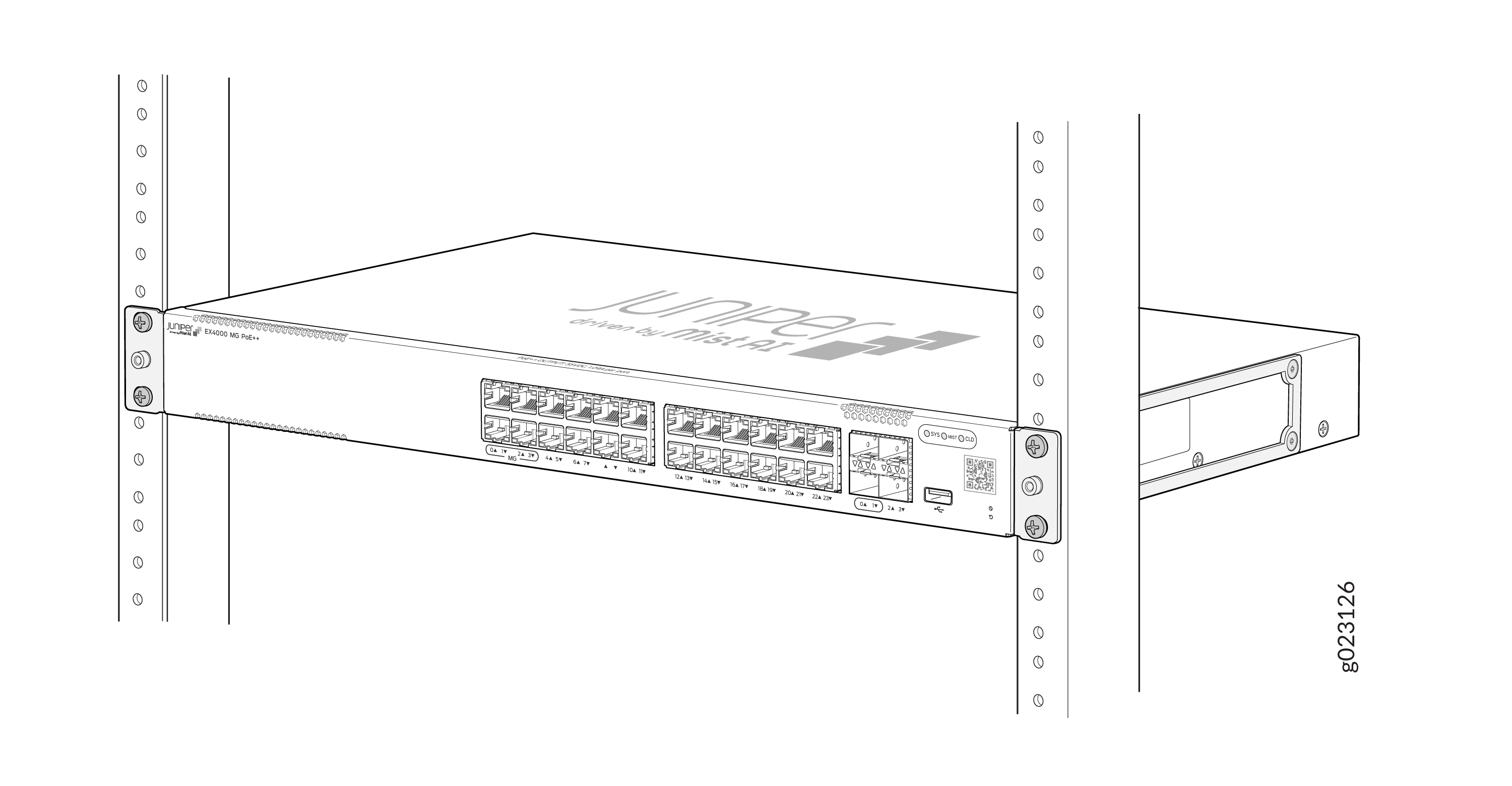
Install the EX4000-24P, EX4000-24T, EX4000-24MP, EX4000-48P, EX4000-48T, and EX4000-48MP in a Rack
Two-post rack mounting is the default mounting option for the EX4000-24P, EX4000-24T, EX4000-24MP, EX4000-48P, EX4000-48T, and EX4000-48MP switches. The mounting kit that ships in the box has the brackets you need to install the switch in a two-post rack. We’ll walk you through how to install the switch in a two-post rack. For the rest of the mounting options refer Install the EX4000 Switch.
What's in the Box?
-
EX4000-24P, EX4000-24T, EX4000-24MP, EX4000-48P, EX4000-48T, or EX4000-48MP switch
-
One AC power cord appropriate for your geographical location
-
Power cord retainer
-
Two-post rack mounting kit with four M4 x 6 mm screws
-
Documentation roadmap card
-
Preinstalled dust covers for SFP ports
What Else Do I Need?
-
Someone to help you secure the switch to the rack
-
Mounting screws to secure the switches to the rack
-
A number two Phillips (+) screwdriver
-
A serial-to-USB adapter (if your laptop doesn’t have a serial port)
-
An electrostatic discharge (ESD) grounding strap
-
A management host such as a laptop or desktop PC
-
Two M5 x 10 mm screws with washers to secure the grounding lug
-
A grounding cable (yellow green): 6 AWG (13 mm²), minimum 90 °C stranded copper wire, or as permitted by the local code, with a Panduit LCD6-14AF-L or equivalent lug attached
Before you install, review the following.
-
Place the switch on a flat, stable surface.
-
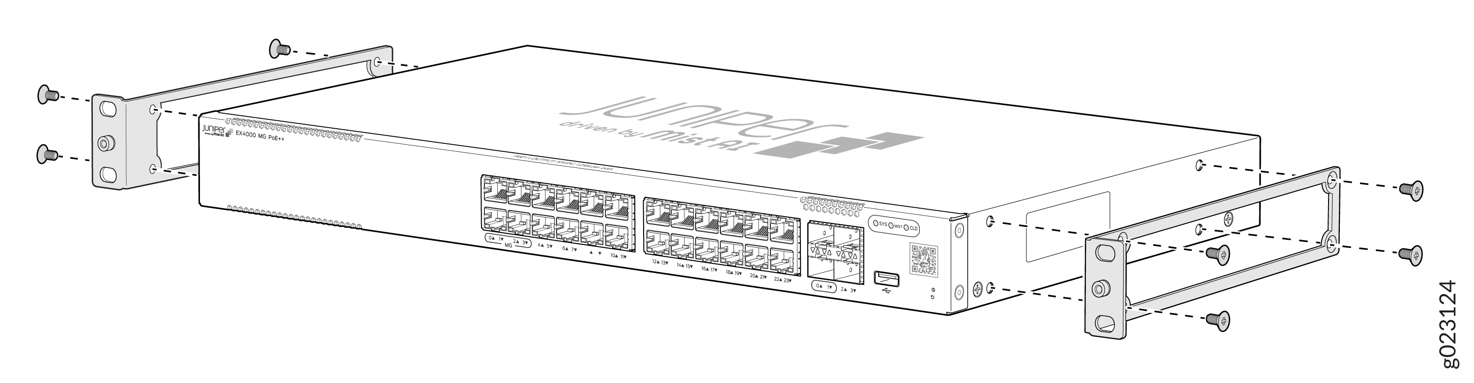
Attach the mounting brackets using the four M4 x 6 mm screws. Use
Phillips(+) screwdriver, number 2. Apply 9.11 lb-in (pounds per inch) of
torque to the screws.
-
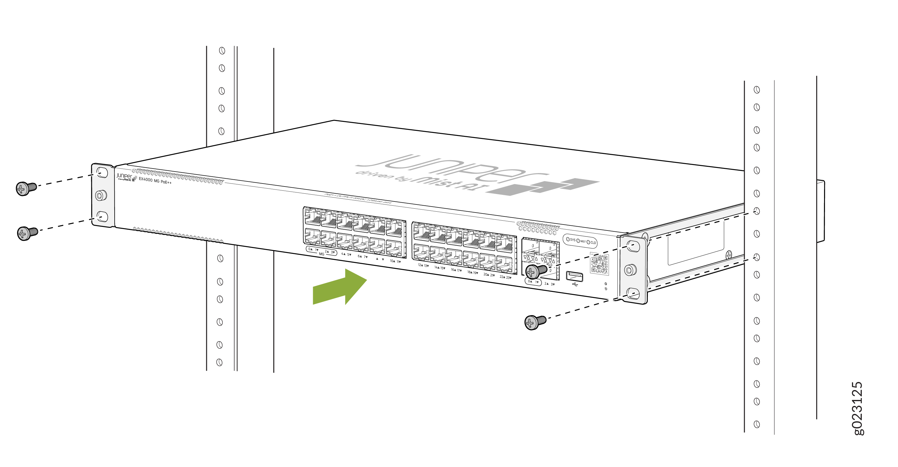
Lift the switch and position it in the rack. Because the fans are inbuilt with
Air Flow Out (AFO)—front-to-back—direction, position the switch so that the rear
of the switch is facing the hot aisle and the front of the switch is facing the
cold aisle. Line up the bottom hole in each mounting bracket with a hole in each
rack post, ensuring that the switch is level.
-
While you’re holding the switch in place, have a second person insert and
tighten the rack mount screws to secure the mounting brackets to the rack posts.
Tighten the screws in the two bottom holes first, and then tighten the screws in
the two top holes. Check that the mounting brackets on each side of the rack are
aligned with each other.
Connect to Power
To connect the EX4000 switch to AC power, you must do the following:
Ground the EX4000 Switch
To ground the EX4000 switch, do the following:
-
Connect one end of the grounding cable to a proper earth ground, such as the rack in which the switch is mounted.
-
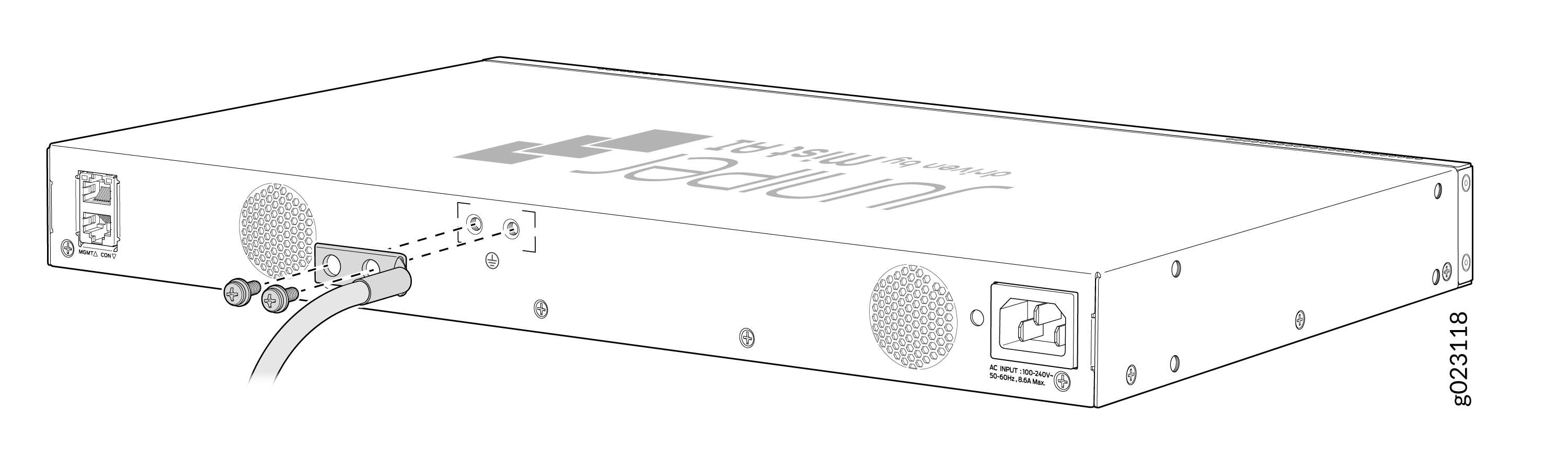
Place the grounding lug attached to the grounding cable over the protective earthing terminal on the rear panel.
-
Attach the grounding lug to the EX4000-8P Switch.
-
Attach the grounding lug to the EX4000-12T Switch.
-
Attach the grounding lug to the EX4000-12P and EX4000-12MP Switches.
-
Attach the grounding lug to the EX4000-24P, EX4000-24T, EX4000-48P, EX4000-48T, EX4000-24MP, or EX4000-48MP Switch.
-
-
Secure the grounding lug to the protective earthing terminal with the M5 x 10 mm screws and washers.
-
Secure the grounding cable and ensure that it does not touch or block access to the switch.
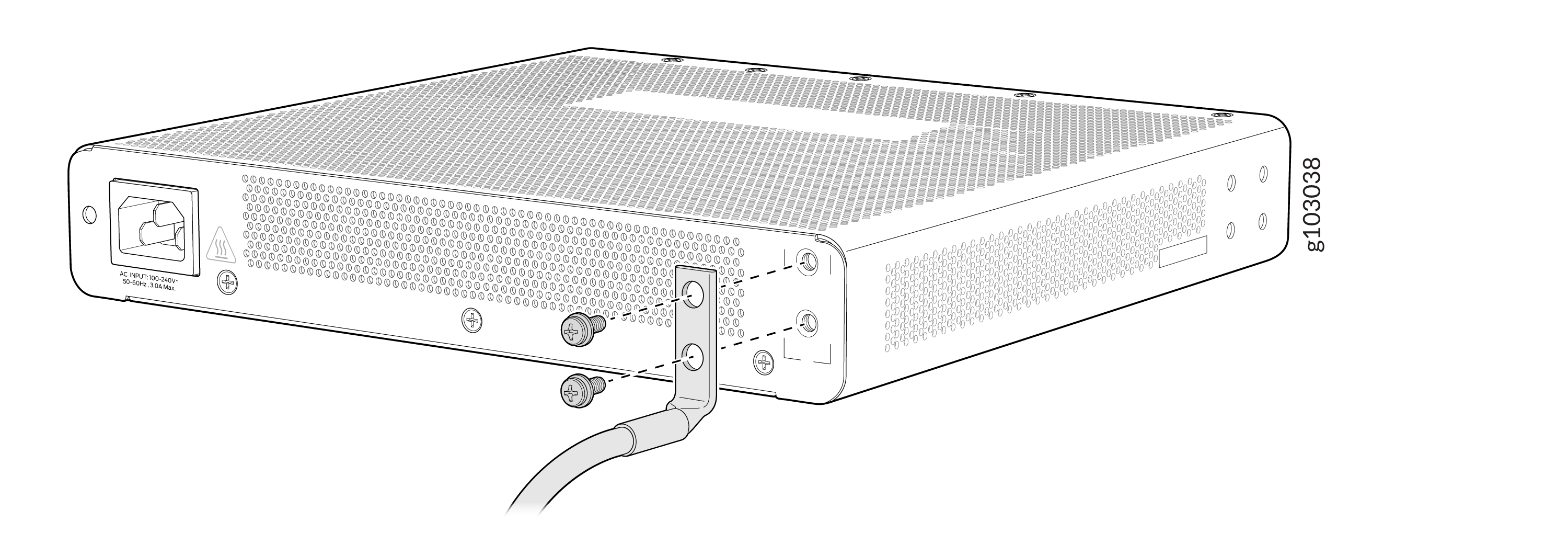
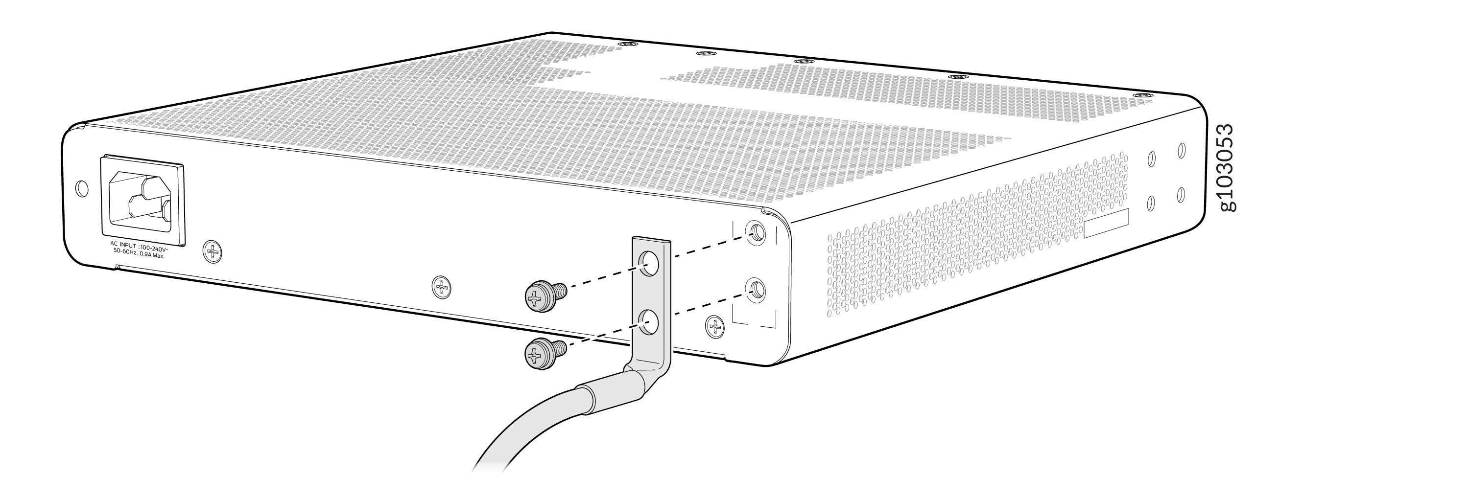
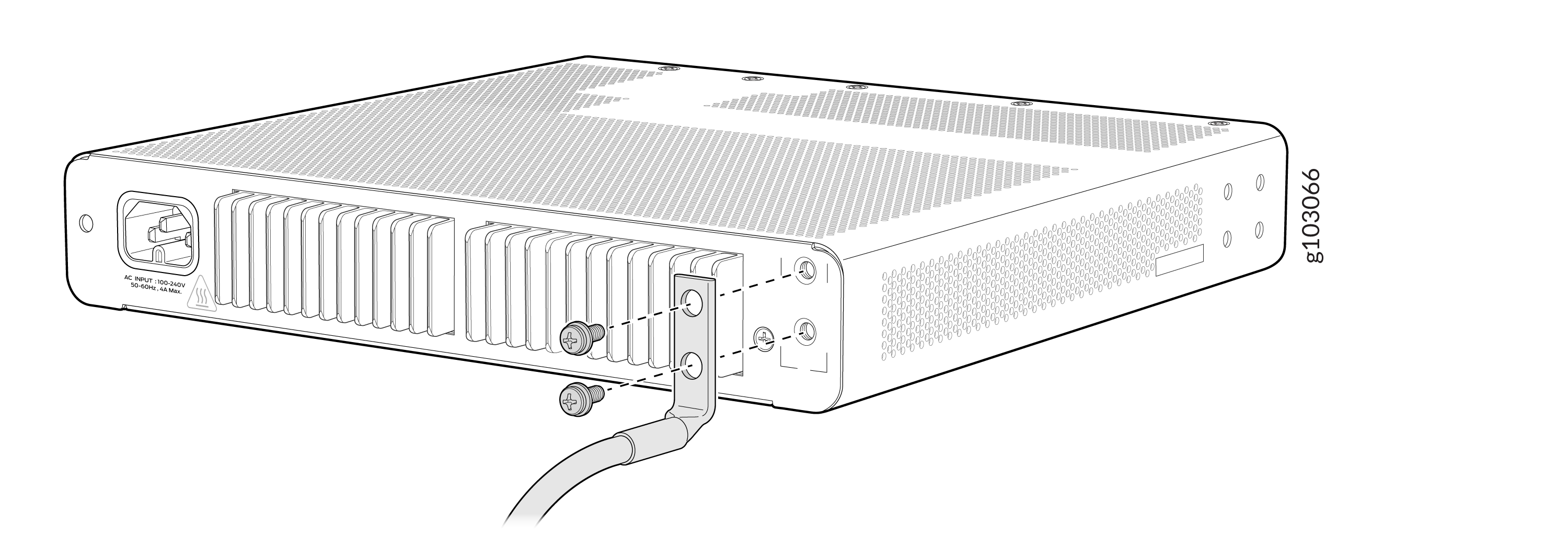
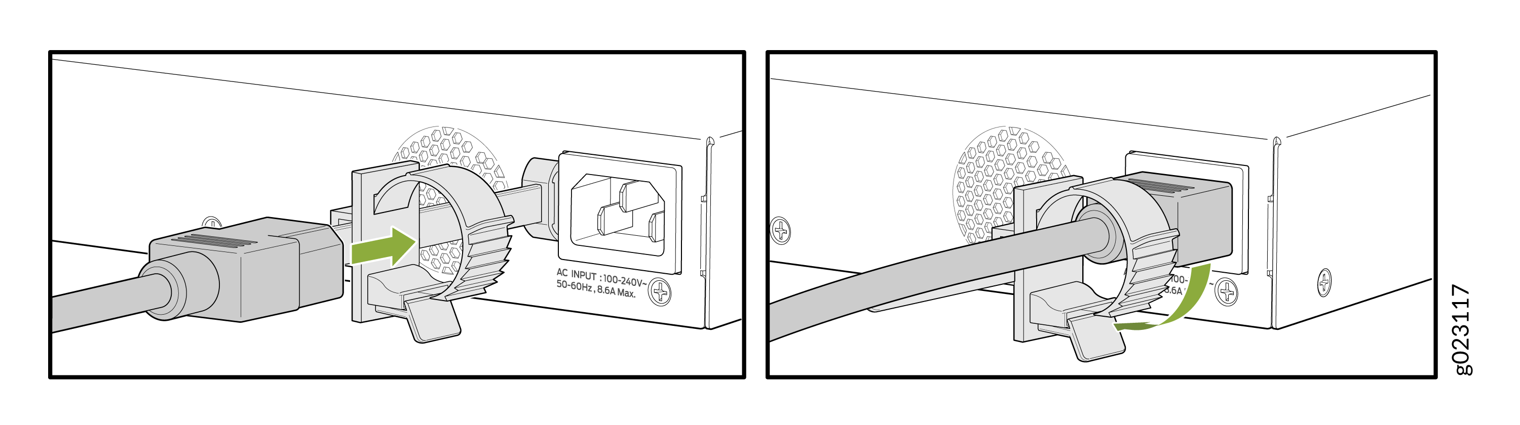
Connect the Power Cord and Power On the Switch
For information about the supported AC power cord specifications, see Table 3.
To connect the power cord, do the following:
-
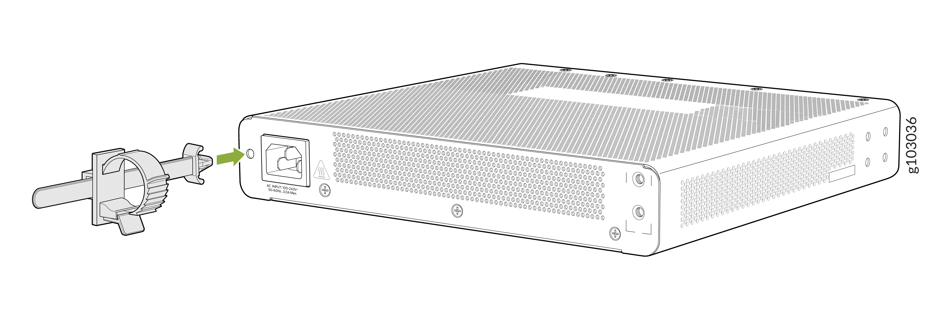
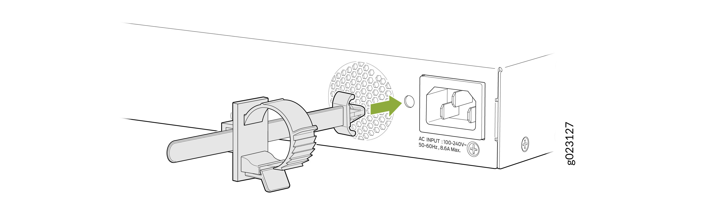
On the rear panel of the switch, insert the power cord retainer into the power cord retainer slot.
-
Connect the Power Cord Retainer to EX4000-8P, EX4000-12T, EX4000-12P, and EX4000-12MP
-
Connect the Power Cord Retainer to EX4000-24P, EX4000-24T, EX4000-48P, EX4000-48T, EX4000-24MP or EX4000-48MP
-
-
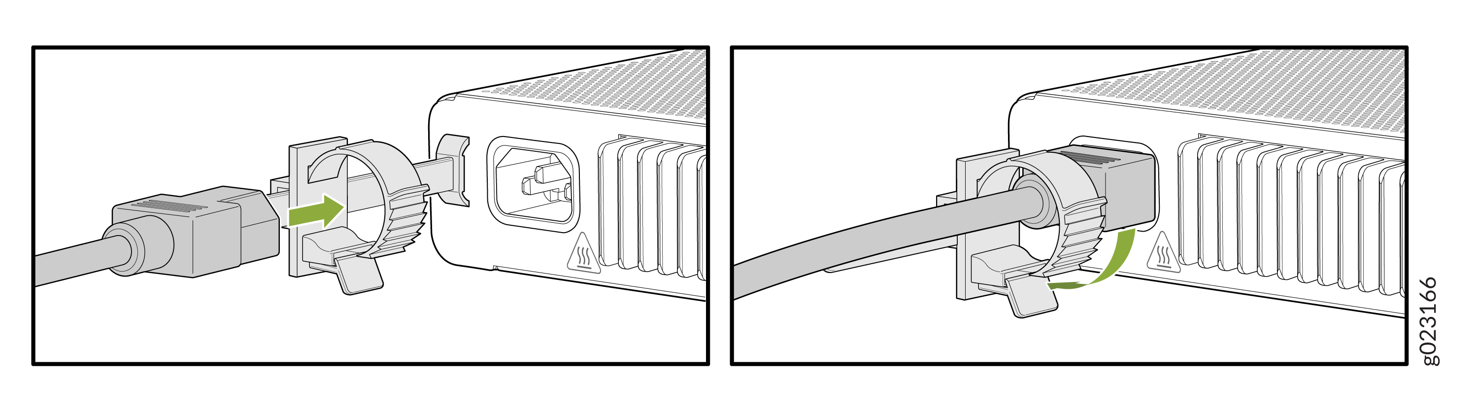
On the rear panel of the switch, insert the AC power cord plug into the power socket. Press the tab on the power cord retainer loop until the loop is snug against the base of the coupler.
-
Connect the power cord to EX4000-8P, EX4000-12P, EX4000-12T, and EX4000-12MP and secure it using the power cord retainer.
-
Connect the power cord to the EX4000-24P, EX4000-24T, EX4000-48P, EX4000-48T, EX4000-24MP or EX4000-48MP and secure it using the power cord retainer.
-
- If the AC power source outlet has a power switch, turn it off.
-
Insert the power cord plug into an AC power source outlet.
-
If the AC power source outlet has a power switch, turn it on. The switch powers on as soon as you provide power to the switch. There is no power switch on the device.