Help us improve your experience.

Let us know what you think.

Do you have time for a two-minute survey?


Installing the Juniper ATP Appliance Collector Open Virtual Appliance (OVA)

Juniper ATP Appliance’s extensible deployment options include a Virtual Collector (vCollector) product, as an Open Virtual Appliance, or OVA, that runs in virtual machines. Specifically, a Juniper ATP Appliance OVA-packaged image is available for VMware Hypervisor for vSphere 6.5, 6.0, 5.5 and 5.0. Virtual Collector models supporting 25 Mbps, 100 Mbps, 500 Mbps and a 1.0 Gbps are available.

An OVF package consists of several files contained in a single directory with an OVF descriptor file that describes the Juniper ATP Appliance virtual machine template and package: metadata for the OVF package, and a Juniper ATP Appliance software image. The directory is distributed as an OVA package (a tar archive file with the OVF directory inside).
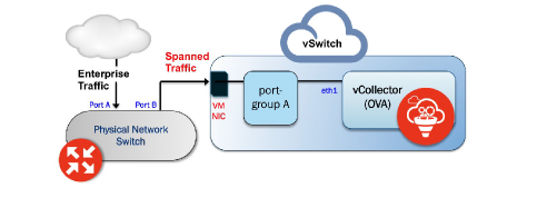
Figure 1: Both the vSwitch and the port-group are in promiscuous modeBoth the vSwitch and the port-group are in promiscuous mode

Virtual Collector Deployment Options

Two types of vCollector deployments are supported for a network switch SPAN/TAP:

  1. Traffic that is spanned to a vCollector from a physical switch. In this case, traffic is spanned from portA to portB. ESXi containing the Juniper ATP Appliance vCollector OVA is connected to portB. This deployment scenario is shown in the figure above.

  2. Traffic from a virtual machine that is on the same vSwitch as the vCollector. In this deployment scenario, because the vSwitch containing the vCollector is in promiscuous mode, by default all port-groups created will also be in promiscuous mode. Therefore, 2 port groups are recommended wherein port-groupA (vCollector) in promiscuous mode is associated with the vCollector, and port-groupB (vTraffic) represents traffic that is not in promiscuous mode.

    Note:

    Traffic from a virtual machine that is not on the same vSwitch as the vCollector is not supported. Also, a dedicated NIC adapter is required for the vCollector deployment; attach the NIC to a virtual switch in promiscuous mode (to collect all traffic). If a vSwitch is in promiscuous mode, by default all port-groups are put in promiscuous mode and that means other regular VMs are also receiving unnecessary traffic. A workaround for that is to create a different port-group for the other VMs and configure without promiscuous mode.

Table 1: Provisioning Requirements

VM vCenter Version Support

Recommended vCollector ESXi Hardware

vCollector CPUs

vCollector Memory

VM vCenter Server Version: 6.5, 6.0, 5.5 and 5.0

vSphere Client Version: 6.5, 6.0, 5.5 and 5.0

ESXi version: 5.5.0 and 5.5.1

Processor speed 2.3-3.3 GHz

As many physical CORES as virtual CPUs

Hyperthreading: either enable or disable

Reservation: Default

CPU Limit: Unlimited

Hyperthreaded Core Sharing Mode: None (if Hyperthreading is enabled on the ESXi)

Memory Reservation: Default

Memory Limit: Unlimited

Table 2: Sizing Options

Model

Performance

Number of vCPUs

Memory

Disk Storage

Emails/Day

vC--v500M

500 Mbps

8

16 GB

512 GB

720 thousand

vC--v1G

1 Gbps

16

16 GB

512 GB

1.4 million

vC-v2.5G

2.5 Gbps

24

32 GB

512 GB

2.4 million

Note:

VDS and DVS are not supported in this release.

OVA Deployment vSwitch Setup

  1. Identify the physical network adapter from which the spanned traffic is received, then create a new VMware Virtual Switch and associate it with the physical network adapter.
  2. Click on Virtual Switch Properties. On the Ports tab, select vSwitch and click on the Edit button.
  3. Select the Security tab and change Promiscuous Mode to accept, then click OK. Click OK again to exit.
  4. Create a new port-group “vtraffic” in the Virtual Switch. This new port-group will be assigned to your vCollector later. See vSwitch Tip below for information about troubleshooting this setup.

To install the ATP Appliance Appliance OVA to a VM

  1. Download the ATP Appliance OVA file to a desktop system that can access VMware vCenter.
  2. Connect to vCenter and click on File>Deploy OVF Template.
  3. Browse the Downloads directory and select the OVA file, then click Next to view the OVF Template Details page.
  4. Click Next to display and review the End User License Agreement page
  5. Accept the EULA and click Next to view the Name and Location page
  6. a default name is created for the Virtual Email Collector. If desired, enter a new name.
  7. Choose the Data Center on which the vCollector will be deployed, then click Next to view the Host/Cluster page.
  8. Choose the host/cluster on which the vCollector will reside, then click Next to view the Storage page.
  9. Choose the destination file storage for the vCollector virtual machine files, then click Next to view the Disk Format page. The default is THIN PROVISION LAZY ZEROED which requires 512GB of free space on the storage device. Using Thin disk provisioning to initially save on disk space is also supported.

    Click Next to view the Network Mapping page.

  10. Set up the Virtual Email Collector management interface: This interface is used to communicate with the ATP Appliance Central Manager (CM). Assign the destination network to the port-group that has connectivity to the CM Management Network IP Address.
  11. IP Allocation Policy can be configured for DHCP or Static addressing-- Juniper recommends using STATIC addressing. For DHCP instructions, skip to Step 12. For IP Allocation Policy as Static, perform the following assignments:
    • IP Address: Assign the Management Network IP Address for the Virtual Collector; it should be in the same subnet as the management IP address for the ATP Appliance Central Manager.

    • Netmask: Assign the netmask for the Virtual Collector.

    • Gateway: Assign the gateway for the Virtual Collector.

    • DNS Address 1: Assign the primary DNS address for the Virtual Collector.

    • DNS Address 2: Assign the secondary DNS address for the Virtual Collector.

  12. Enter the Search Domain and Hostname for the Virtual Collector.
  13. Complete the ATP Appliance vCollector Settings:
    • New ATP Appliance CLI Admin Password: this is the password for accessing the Virtual Collector from the CLI.

    • ATP Appliance Central Manager IP Address: Enter the management network IP Address configured for the Central Manager. This IP Address should be reachable by the Virtual Collector Management IP Address.

    • ATP Appliance Device Name: Enter a unique device name for the Virtual Collector.

    • ATP Appliance Device Description: Enter a description for the Virtual Collector.

    • ATP Appliance Device Key Passphrase: Enter the passphrase for the Virtual Collector; it should be identical to the passphrase configured in the Central Manager for the Core/CM. Click Next to view the Ready to Complete page.

  14. Do not check the Power-On After Deployment option because you must first (next) modify the CPU and Memory requirements (depending on the sizing options available). It is important to reserve CPU and memory for any virtual deployment.
  15. To configure CPU and memory reservation:
    • For CPU reservation: Right click on vCollector-> Edit settings:

    • Select Resources tab, then select CPU.

    • Under Reservation, specify the guaranteed CPU allocation for the VM. It can be calculated based on Number of vCPUs processor speed.

    • For Memory Reservation: Right click on vCollector -> Edit settings.

    • In the Resources tab, select Memory.

    • Under Reservation, specify the amount of Memory to reserve for the VM. It should be the same as the memory specified by the Sizing guide.

  16. If Hyperthreading is enabled, perform the followings elections:
    • Right click on the virtual collector -> Edit settings.

    • In the Resources tab, select HT Sharing: None for Advanced CPU.

  17. Power on the Virtual Email Collector.