ON THIS PAGE
Inter-Chassis Stateful Synchronization for Long Lived NAT and Stateful Firewall Flows (MS-MPC, MS-MIC) (Release 16.1 and later)
Configuring Inter-chassis MS-MPC and MS-MIC Redundancy for NAT and Stateful Firewall Overview (Release 16.1 and later)
This topic applies to Junos OS release 16.1 and higher.
Carrier-grade NAT (CGN) and stateful firewall deployments can use a dual-chassis implementation to provide a redundant data path and redundancy for key components in the router. Although intra-chassis high availability can be used in an MX Series device by employing the AMS interfaces, this method only deals locally with service PIC and full MS-MPC or MS-MIC card failures. If for any reason traffic is switched to a backup router due to some other failure in the router, the session state from the Service PICs is lost. Inter-chassis high availability offers a more robust solution by preserving the session state of NAT and stateful firewalls from the services PICs. This technology is a primary-secondary model, not an active-active cluster. Traffic to be serviced by the services PICs that are configured for inter-chassis high availability only flows through the MX Series device that is currently the primary in the pair.
To configure interchassis redundancy for NAT and stateful firewall, you configure:
Stateful synchronization, which replicates the session state from the services PICs on the primary chassis to the backup chassis. For more information, see Inter-Chassis Stateful Synchronization for Long Lived NAT and Stateful Firewall Flows (MS-MPC, MS-MIC) Overview (Release 16.1 and later).
The service redundancy daemon, which allows primary-role switchover to occur based on a monitored event. Most operators would not want to employ stateful synchronization without also implementing the service redundancy daemon. For more information, see Service Redundancy Daemon Overview
Inter-Chassis Stateful Synchronization for Long Lived NAT and Stateful Firewall Flows (MS-MPC, MS-MIC) Overview (Release 16.1 and later)
This topic applies to Junos OS release 16.1 and higher.
Stateful synchronization synchronizes long-lived sessions between the primary and backup MX Series chassis in the high availability pair. By default, long lived sessions are stateful firewall, NAT, and IDS sessions that have been active on the services PIC for 180 seconds, though you can configure this to be a higher or lower value. Stateful firewall sessions, NAT sessions, and IDS sessions are the session types that can be synchronized.
Inter-chassis high availability works with ms- service interfaces
configured on MS-MIC or MS-MPC interface cards. An ms- interface unit
other than unit 0 must be configured with the ip-address-owner
service-plane option.
The following NAT translation types and sessions support stateful synchronization:
basic-nat44
dynamic-nat44
napt-44
napt-44 with endpoint-independent mapping (EIM), or endpoint-independent filters (EIF)
dnat-44
twice-nat
stateful-nat64
The following restrictions apply:
Replicating state information for the port block allocation (PBA), endpoint-independent mapping (EIM), or endpoint-independent filters (EIF) features is not supported.
When configuring a service set for NAT or stateful firewall that belongs to a stateful synchronization setup, - the NAT and stateful firewall configurations for the service set must be identical on both MX Series devices.
Application Layer Gateway (ALG) sessions do not support stateful synchronization.
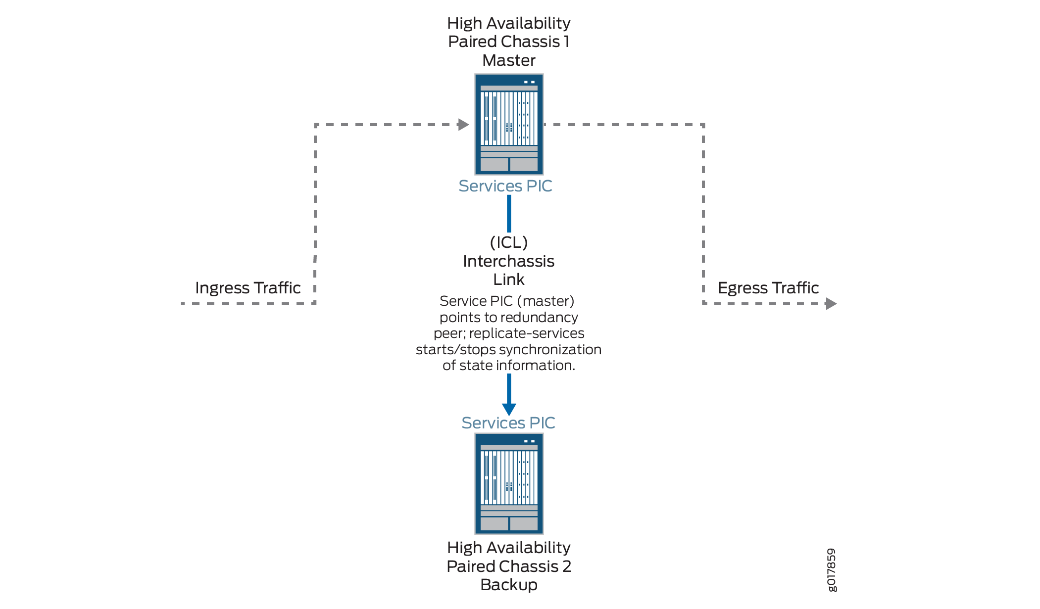
Figure 1 shows the inter-chassis high availability topology.
Configuring Inter-Chassis Stateful Synchronization for Long Lived NAT and Stateful Firewall Flows (MS-MPC, MS-MIC) (Release 16.1 and later)
This topic applies to Junos OS release 16.1 and higher.
To configure stateful synchronization inter-chassis high availability for stateful firewall and NAPT44 on MS-MIC or MS-MPC service PICs, perform the following configuration steps on each chassis of the high availability pair.
Example: Inter-Chassis Stateful Synchronization for Long-Lived NAT and Stateful Firewall Flows (MS-MIC, MS-MPC) (Release 16.1 and later)
This example shows how to configure inter-chassis high availability for NAT services.
Requirements
This example uses the following hardware and software components:
Two MX480 routers with MS-MPC line cards
Junos OS Release 16.1 or later
Overview
Two MX Series routers are identically configured to facilitate stateful failover for NAT services in case of a chassis failure.
Configuration
To configure inter-chassis high availability for this example, perform these tasks:
- CLI Quick Configuration
- Configuring Interfaces for Chassis 1
- Configure Routing Information for HA Synchronization Traffic Between MX Series Routers for Chassis 1
- Configuring NAT for Chassis 1
- Configuring the Service Set
- Configuring Interfaces for Chassis 2
- Configure Routing Information for HA Synchronization Traffic Between MX Series Routers for Chassis 2
CLI Quick Configuration
To quickly configure this example on the routers, copy the following commands and paste them into the router terminal window after removing line breaks and substituting interface information specific to your site.
The following configuration is for chassis 1.
[edit] set interfaces ms-4/0/0 redundancy-options redundancy-peer ipaddress 5.5.5.2 set interfaces ms-4/0/0 redundancy-options redundancy-local data-address 5.5.5.1 set interfaces ms-4/0/0 redundancy-options routing-instance HA set interfaces ms-4/0/0 redundancy-options replication-threshold 180 set interfaces ms-4/0/0 unit 10 ip-address-owner service-plane set interfaces ms-4/0/0 unit 10 family inet address 5.5.5.1/32 set interfaces ms-4/0/0 unit 20 family inet set interfaces ms-4/0/0 unit 20 service-domain inside set interfaces ms-4/0/0 unit 30 family inet set interfaces ms-4/0/0 unit 30 service-domain outside set interfaces ge-2/0/0 vlan-tagging set interfaces ge-2/0/0 unit 0 vlan-id 100 family inet address 20.1.1.1/24 set policy-options policy-statement dummy term 1 then reject set routing-instances HA instance-type vrf set routing-instances HA interface ge-2/0/0.0 set routing-instances HA interface ms-4/0/0.10 set routing-instances HA route-distinguisher 1:1 set routing-instances HA vrf-import dummy set routing-instances HA vrf-export dummy set routing-instances HA routing-options static route route 5.5.5.1/32 next-hop ms-4/0/0.10 set routing-instances HA routing-options static route route 5.5.5.2/32 next-hop 20.1.1.2 set routing-options static-route 100.100.100.0/24 next-hop ms-4/0/0.20 set services nat pool p2 address 32.0.0.0/24 set services nat pool p2 port automatic random-allocation set services nat pool p2 address-allocation round-robin set services nat rule r2 match-direction input set services nat rule r2 term t1 from source-address 129.0.0.0/8 set services nat rule r2 term t1 from source-address 128.0.0.0/8 set services nat rule r2 term t1 then translated source-pool p2 set services nat rule r2 term t1 then translated translation-type napt-44 set services nat rule r2 term t1 then translated address-pooling paired set services nat rule r2 term t1 then syslog set services service-set ss2 nat-rules r2 set services service-set ss2 next-hop-service inside-service-interface ms-4/0/0.20 set services service-set ss2 next-hop-service outside-service-interface ms-4/0/0.30 set services service-set ss2 syslog host local class session-logs set services service-set ss2 syslog host local class nat-logs
The following configuration is for chassis 2. NAT and service set information must be identical for chassis 1 and 2.
set interfaces ms-4/0/0 redundancy-options redundancy-peer ipaddress 5.5.5.1 set interfaces ms-4/0/0 redundancy-options redundancy-local data-address 5.5.5.2 set interfaces ms-4/0/0 redundancy-options routing-instance HA set interfaces ms-4/0/0 redundancy-options replication-threshold 180 set interfaces ms-4/0/0 unit 10 ip-address-owner service-plane set interfaces ms-4/0/0 unit 10 family inet address 5.5.5.2/32 set interfaces ms-4/0/0 unit 20 family inet set interfaces ms-4/0/0 unit 20 service-domain inside set interfaces ms-4/0/0 unit 30 family inet set interfaces ms-4/0/0 unit 30 service-domain outside set interfaces ge-2/0/0 vlan-tagging set interfaces ge-2/0/0 unit 0 vlan-id 100 family inet address 20.1.1.2/24 set policy-options policy-statement dummy term 1 then reject set routing-instances HA instance-type vrf set routing-instances HA interface ge-2/0/0.0 set routing-instances HA interface ms-4/0/0.10 set routing-instances HA route-distinguisher 1:1 set routing-instances HA vrf-import dummy set routing-instances HA vrf-export dummy set routing-instances HA routing-options static route 5.5.5.2/32 next-hop ms-4/0/0.10 set routing-instances HA routing-options static route 5.5.5.1/32 next-hop 20.1.1.1 set routing-options static-route 100.100.100.0/24 next-hop ms-4/0/0.20 set services nat pool p2 address 32.0.0.0/24 set services nat pool p2 port automatic random-allocation set services nat pool p2 address-allocation round-robin set services nat rule r2 match-direction input set services nat rule r2 term t1 from source-address 129.0.0.0/8 set services nat rule r2 term t1 from source-address 128.0.0.0/8 set services nat rule r2 term t1 then translated source-pool p2 set services nat rule r2 term t1 then translated translation-type napt-44 set services nat rule r2 term t1 then translated address-pooling paired set services nat rule r2 term t1 then syslog set services service-set ss2 nat-rules r2 set services service-set ss2 next-hop-service inside-service-interface ms-4/0/0.20 set services service-set ss2 next-hop-service outside-service-interface ms-4/0/0.30 set services service-set ss2 syslog host local class session-logs set services service-set ss2 syslog host local class nat-logs
Configuring Interfaces for Chassis 1
Step-by-Step Procedure
The interfaces for each of the HA pair of routers are configured identically with the exception of the following service PIC options:
The
redundancy-options redundancy-peer ipaddress addressmust be different on each chassis and must point to theredundancy-options redundancy-local data-address data-addresson the peer chassis.The
unit unit-number family inet address addressof a unit, other than 0, that contains theip-address-owner service-planeoption must be different on each chassis.
To configure interfaces:
Configure the redundant service PIC on chassis 1.
[edit interfaces} user@host# set interfaces ms-4/0/0 redundancy-options redundancy-peer ipaddress 5.5.5.2 user@host# set interfaces ms-4/0/0 redundancy-options redundancy-local data-address 5.5.5.1 user@host# set interfaces ms-4/0/0 redundancy-options routing-instance HA user@host# set interfaces ms-4/0/0 redundancy-options replication-threshold 180 user@host# set interfaces ms-4/0/0 unit 10 ip-address-owner service-plane user@host# set interfaces ms-4/0/0 unit 10 family inet address 5.5.5.1/32 user@host# set interfaces ms-4/0/0 unit 20 family inet user@host# set interfaces ms-4/0/0 unit 20 service-domain inside user@host# set interfaces ms-4/0/0 unit 30 family inet user@host# set interfaces ms-4/0/0 unit 30 service-domain outside
Configure the interfaces for chassis 1 that are used as interchassis links for synchronization traffic.
user@host# set interfaces ge-2/0/0 vlan-tagging user@host# set interfaces ge-2/0/0 unit 0 vlan-id 100 family inet address 20.1.1.1/24
Configure remaining interfaces as needed.
Results
user@host# show interfaces
ge-2/0/0 {
vlan-tagging;
unit 0 {
vlan-id 100;
family inet {
address 20.1.1.1/24;
}
}
}
ms-4/0/0 {
redundancy-options {
redundancy-peer {
address 5.5.5.2;
}
redundancy-local {
data-address 5.5.5.1;
}
routing-instance HA;
}
unit 10 {
ip-address-owner service-plane;
family inet {
address 5.5.5.1/32;
}
}
unit 20 {
family inet;
family inet6;
service-domain inside;
}
unit 30 {
family inet;
family inet6;
service-domain outside;
}
}Configure Routing Information for HA Synchronization Traffic Between MX Series Routers for Chassis 1
Step-by-Step Procedure
Detailed routing configuration is not included for this example. A routing instance is required for the HA synchronization traffic between the chassis as follows:
To configure the routing instances for chassis 1:
Specify a dummy policy statement. This statement is referenced in the routing instance configuration.
user@host# set policy-options policy-statement dummy term 1 then reject
Specify the options for the routing instance.
user@host# set routing-instances HA instance-type vrf user@host# set routing-instances HA interface ge-2/0/0.0 user@host# set routing-instances HA interface ms-4/0/0.10 user@host# set routing-instances HA route-distinguisher 1:1 user@host# set policy-options policy-statement dummy term 1 then reject user@host# set routing-instances HA vrf-import dummy user@host# set routing-instances HA vrf-export dummy @user@host# set routing-instances HA routing-options static route 5.5.5.1/32 next-hop ms-4/0/0.10 user@host# set routing-instances HA routing-options static route 5.5.5.2/32 next-hop 20.1.1.2
Specify the next-hop traffic to which the service set is applied.
user@host# set routing-options static-route 100.100.100.0/24 next-hop ms-4/0/0.20
Results
@user@host# show routing-instances
HA {
instance-type vrf;
interface ge-2/0/0.0;
interface ms-4/0/0.10;
route-distinguisher 1:1;
vrf-import dummy;
vrf-export dummy;
routing-options {
static {
route 5.5.5.1/32 next-hop ms-4/0/0.10;
route 5.5.5.2/32 next-hop 20.1.1.2;
}
}
}Configuring NAT for Chassis 1
Step-by-Step Procedure
Configure NAT identically on both routers.
To configure NAT:
Specify NAT pool and rule information..
user@host# set services nat pool p2 address 32.0.0.0/24 user@host# set services nat pool p2 port automatic random-allocation user@host# set services nat pool p2 address-allocation round-robin user@host# set services nat rule r2 match-direction input user@host# set services nat rule r2 term t1 from source-address 129.0.0.0/8 user@host# set services nat rule r2 term t1 from source-address 128.0.0.0/8 user@host# set services nat rule r2 term t1 then translated source-pool p2 user@host# set services nat rule r2 term t1 then translated translation-type napt-44 user@host# set services nat rule r2 term t1 then translated address-pooling paired user@host# set services nat rule r2 term t1 then syslog
Results
user@host# show services nat
nat {
pool p2 {
address 32.0.0.0/24;
port {
automatic {
random-allocation;
}
}
address-allocation round-robin;
}
rule r2 {
match-direction input;
term t1 {
from {
source-address {
129.0.0.0/8;
128.0.0.0/8;
}
}
then {
translated {
source-pool p2;
translation-type {
napt-44;
}
address-pooling paired;
}
syslog;
}
}
}
}Configuring the Service Set
Step-by-Step Procedure
Configure the service set identically on both routers. To configure the service set:
(Optional) Service sets are replicated by default. To exclude a service set from replication using the following option.
user@host# set services service-set ss2 replicate-services disable-replication-capability
Configure references to NAT rules for the service set.
user@host# set services service-set ss2 nat-rules r2
Configure next-hop service interface on the MS-PIC.
user@host# set services service-set ss2 next-hop-service inside-service-interface ms-4/0/0.20 user@host# set services service-set ss2 next-hop-service outside-service-interface ms-4/0/0.30
Configure desired logging options.
user@host# set services service-set ss2 syslog host local class session-logs user@host# set services service-set ss2 syslog host local class nat-logs
Results
user@host# show services service-set ss2
syslog {
host local {
class {
session-logs;
inactive:
nat-logs;
}
}
replicate-services {
replication-threshold 180;
inactive: disable-replication-capability;
}
nat-rules r2;
next-hop-service {
inside-service-interface ms-3/0/0.20;
outside-service-interface ms-3/0/0.30;
}
}Configuring Interfaces for Chassis 2
Step-by-Step Procedure
The interfaces for each of the HA pair of routers are configured identically with the exception of the following service PIC options:
redundancy-options redundancy-peer ipaddress addressunit unit-number family inet address addressof a unit, other than 0, that contains theip-address-owner service-planeoption
Configure the redundant service PIC on chassis 2.
The
redundancy-peer ipaddresspoints to the address of the unit (unit 10) on ms-4/0/0 on chassis on chassis 1 that contains theip-address-owner service-planestatement.[edit interfaces} set interfaces ms-4/0/0 redundancy-options redundancy-peer ipaddress 5.5.5.1 user@host# set interfaces ms-4/0/0 redundancy-options redundancy-local data-address 5.5.5.2 user@host# set interfaces ms-4/0/0 redundancy-options replication-threshold 180 user@host# set interfaces ms-4/0/0 redundancy-options routing-instance HA user@host# set interfaces ms-4/0/0 unit 10 ip-address-owner service-plane user@host# set interfaces ms-4/0/0 unit 10 family inet address 5.5.5.2/32 user@host# set interfaces ms-4/0/0 unit 20 family inet user@host# set interfaces ms-4/0/0 unit 20 service-domain inside user@host# set interfaces ms-4/0/0 unit 30 family inet user@host# set interfaces ms-4/0/0 unit 30 service-domain outside
Configure the interfaces for chassis 2 that are used as interchassis links for synchronization traffic
user@host# set interfaces ge-2/0/0 vlan-tagging user@host# set interfaces ge-2/0/0 unit 0 vlan-id 100 family inet address 20.1.1.2/24
Configure remaining interfaces for chassis 2 as needed.
Results
user@host# show interfaces
ms-4/0/0 {
redundancy-options {
redundancy-peer {
address 5.5.5.1;
}
redundancy-local {
data-address 5.5.5.2;
}
routing-instance HA;
}
unit 0 {
family inet;
}
unit 10 {
ip-address-owner service-plane;
family inet {
address 5.5.5.2/32;
}
}
}
ge-2/0/0 {
vlan-tagging;
unit 0 {
vlan-id 100;
family inet {
address 20.1.1.2/24;
}
}
unit 10 {
vlan-id 10;
family inet {
address 2.10.1.2/24;
}
}
}Configure Routing Information for HA Synchronization Traffic Between MX Series Routers for Chassis 2
Step-by-Step Procedure
Detailed routing configuration is not included for this example. A routing instance is required for the HA synchronization traffic between the two chassis and is included here.
Configure routing instances for chassis 2.
user@host# set routing-instances HA instance-type vrf
user@host# set routing-instances HA interface ge-2/0/0.0
user@host# set routing-instances HA interface ms-4/0/0.10
user@host# set routing-instances HA route-distinguisher 1:1
user@host# set policy-options policy-statement dummy term 1 then reject
user@host# set routing-instances HA vrf-import dummy
user@host# set routing-instances HA vrf-export dummy
user@host# set routing-instances HA routing-options static route 5.5.5.2/32 next-hop ms-4/0/0.10
user@host# set routing-instances HA routing-options static route 5.5.5.1/32 next-hop 20.1.1.1
user@host# set routing-options static-route 100.100.100.0/24 next-hop ms-4/0/0.20
Note:The following configuration steps are identical to the steps shown for chassis 1.
Configuring NAT
Configuring the Service Set
Results
@user@host# show services routing-instances
HA {
    instance-type vrf;
    interface xe-2/2/0.0;
    interface ms-4/0/0.10;
    route-distinguisher 1:1;
    vrf-import dummy;
    vrf-export dummy;
    routing-options {
        static {
            route 5.5.5.2/32 next-hop ms-4/0/0.10;
            route 5.5.5.1/32 next-hop 20.1.1.1;
        }
    }
}