Secure Wire for Logical Systems
Secure Wire for Logical Systems Overview
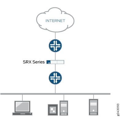
You can forward the traffic that arrives on a specific interface without any change through another interface on logical systems. This mapping of interfaces on logical systems is called secure wire. Secure wire allows an SRX Series Firewall to deploy in the path of network traffic without changing the routing tables or a reconfiguration of neighboring devices. Figure 1 shows a typical in-path deployment of an SRX Series Firewall with secure wire.

Secure wire maps two peer interfaces. It differs from transparent and route modes, and there is no switching or routing lookup to forward traffic. When security policy permits the traffic, secure wire forwards a packet arriving on one peer interface immediately to the other peer interface without change. There is no routing or switching decision made on the packet. Secure wire also forwards the return traffic unchanged. The secure wire feature is supported for both IPv4 and IPv6 traffic on Ethernet logical interfaces only.
Secure wire is a special case of Layer 2 transparent mode on SRX Series Firewalls that provide point-to-point connections. This means that the two interfaces of a secure wire must directly connect to Layer 3 entities, such as routers or hosts. You can connect secure wire interfaces to switches. However, note that when security policy permits traffic, a secure wire interface forwards all arriving traffic to the peer interface.
Secure wire can coexist with Layer 3 mode. While you configure Layer 2 and Layer 3 interfaces at the same time, traffic forwarding occurs independently on Layer 2 and Layer 3 interfaces.
Secure wire can coexist with Layer 2 transparent mode. If both features exist on the same SRX Series Firewall, you need to configure them in different VLANs.
Secure wire support for root logical system extends to user logical systems. You can forward traffic immediately that arrives on a specific interface to another interface without modifying any received frames on the user logical systems.
Limitations
Secure wire doesn't support:
IRB interface
Z-mode
MPLS label encapsulation
Tenant system
Interconnect logical system
Example: Configure Secure Wire for User Logical Systems
In this example, you can configure secure wire for a user logical system and forward traffic from one interface to another interface without changing any frame.
Requirements
Before you begin:
Configure security profile for a user logical system, see Example: Configuring User Logical Systems Security Profiles.
Overview
In this example, you can configure 10-Gigabit Ethernet interfaces xe-1/0/1 and xe-1/0/2 under a user logical system, called LSYS1. You can configure secure wire resource allocation per logical system. When traffic passes to xe-1/0/1 interface, without changing any frame, secure wire forwards the traffic to xe-1/0/2 interface based on the defined security policy.
Configuration
Procedure
CLI Quick Configuration
To quickly configure this example, copy the
following commands, paste them into a text file, remove any line breaks,
change any details necessary to match your network configuration,
and then copy and paste the commands into the CLI at the [edit] hierarchy level.
user@host#set logical-systems LSYS1 security forwarding-options secure-wire myLSYS1sw01 interface xe-1/0/1.0
user@host#set logical-systems LSYS1 security forwarding-options secure-wire myLSYS1sw01 interface xe-1/0/2.0
user@host#set system security-profile prof1 secure-wire maximum 100
user@host#set system security-profile prof1 secure-wire reserved 1
Step-by-Step Procedure
The following example requires you to navigate various levels in the configuration hierarchy. For instructions on how to do that, see Using the CLI Editor in Configuration Mode in the CLI User Guide.
Configure secure wire under a user logical system.
[edit]
user@host#set logical-systems LSYS1 security forwarding-options secure-wire myLSYS1sw01 interface xe-1/0/1.0
user@host#set logical-systems LSYS1 security forwarding-options secure-wire myLSYS1sw01 interface xe-1/0/2.0
Create the security profile, and specify the number of maximum and reserved quota.
[edit]
user@host#set system security-profile prof1 secure-wire maximum 100
user@host#set system security-profile prof1 secure-wire reserved 1
Results
From configuration mode, confirm your configuration
by entering the show logical-systems LSYS1 security forwarding-options
secure-wire myLSYS1sw01, and show system security-profile
prof1 commands. If the output does not display the intended
configuration, repeat the instructions in this example to correct
the configuration.
user@host#show logical-systems LSYS1 security forwarding-options secure-wire myLSYS1sw01
interface [ xe-1/0/1.0 xe-1/0/2.0 ];
user@host#show system security-profile prof1
    secure-wire {
        maximum 100;
        reserved 1;
    }
    logical-system LSYS1;
If you are done configuring the device, enter commit from configuration mode.
Verification
Confirm that the configuration is working properly.
Verify Secure Wire Mapping
Purpose
Verify the secure wire mapping.
Action
From operational mode, enter the show security
forward-options secure-wire logical-system LSYS1 command.
Logical System       Secure wire                      Interface       Link  Interface       Link

LSYS1                myLSYS1sw01                      xe-1/0/1.0      up    xe-1/0/2.0      up
Total secure wires: 1
Verify Resource Allocation
Purpose
Verify the resource allocation for a user logical system.
Action
From operational mode, enter the show system security-profile
secure-wire logical-system LSYS1 command.
logical-system tenant name   security profile name       usage    reserved     maximum

LSYS1                        prof1                             1           1         100
