Example: Configuring Service Chaining Using a Custom Bridge
This example shows how to configure service chaining using a custom bridge.
Requirements
This example uses the following hardware and software components:
NFX150 running Junos OS Release 18.1R1
Overview
The default system bridge is OVS. The OVS bridge is a VLAN-aware system bridge, which acts as the NFV backplane to which the VNFs and FPCs connect. However, you can choose to create a custom bridge based on your requirement. This example explains how to configure service chaining using a custom bridge.
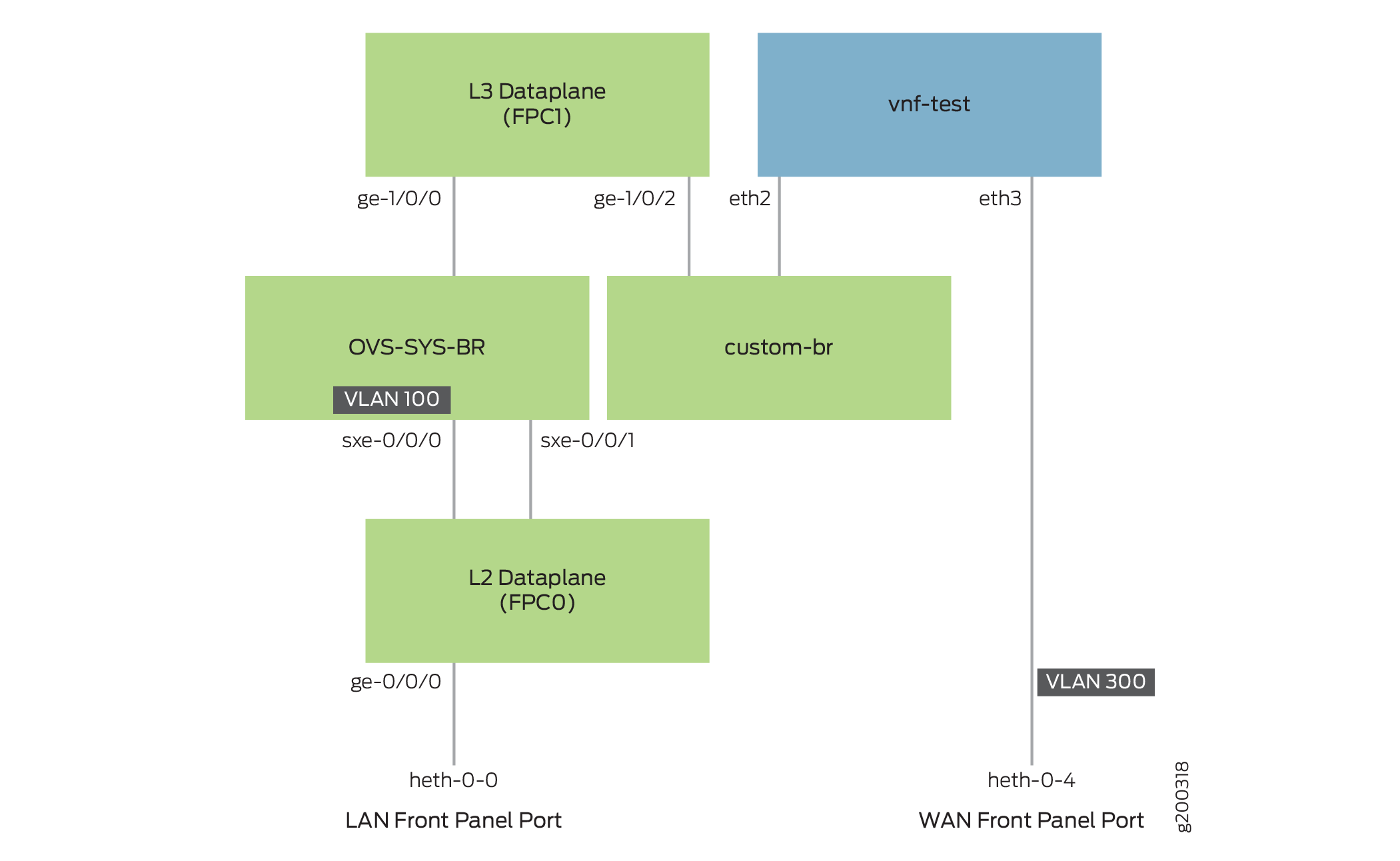
Topology
This example uses the topology shown in Figure 1.
Configuration
- Create VLANs and the Custom Bridge
- Map the Interfaces
- Configure the Layer 2 Datapath
- Configure the Layer 3 Datapath
- Configure the VNF
Create VLANs and the Custom Bridge
Step-by-Step Procedure
Configure VLANs for the LAN-side interfaces.
user@host# set vlans vlan100 vlan-id 100
Create a custom bridge:
user@host# set vmhost vlans custom-br vlan-id none
Map the Interfaces
Step-by-Step Procedure
Map the heth-0-0 physical port to the FPC0 interface.
user@host# set vmhost virtualization-options interfaces ge-0/0/0 mapping interface heth-0-0
Map the FPC1 interface ge-1/0/2 to the custom bridge.
user@host# set vmhost virtualization-options interfaces ge-1/0/2 mapping vlan custom-br
Configure the Layer 2 Datapath
Step-by-Step Procedure
Configure the LAN-side front panel ports and add them to the LAN-side VLAN.
user@host# set interfaces ge-0/0/0 unit 0 family ethernet-switching interface-mode trunk
user@host# set interfaces ge-0/0/0 unit 0 family ethernet-switching vlan members vlan100
Configure the internal-facing interfaces as trunk ports and add them to the LAN-side VLAN. The internal-facing interfaces are typically trunk ports, as they must support traffic from multiple front panel ports and VLANs.
user@host# set interfaces sxe-0/0/0 unit 0 family ethernet-switching interface-mode trunk
user@host# set interfaces sxe-0/0/0 unit 0 family ethernet-switching vlan members vlan100
Configure the Layer 3 Datapath
Step-by-Step Procedure
Configure VLAN tagging on ge-1/0/0:
user@host# set interfaces ge-1/0/0 vlan-tagging
user@host# set interfaces ge-1/0/0 unit 0 vlan-id 100
user@host# set interfaces ge-1/0/0 unit 0 family inet address 192.168.2.1/24
Configure VLAN tagging on ge-1/0/2:
user@host# set interfaces ge-1/0/2 vlan-tagging
user@host# set interfaces ge-1/0/2 unit 0 vlan-id 200
user@host# set interfaces ge-1/0/2 unit 0 family inet address 203.0.113.2/24
Configure the VNF
Step-by-Step Procedure
Launch the VNF:
user@host# set virtual-network-functions vnf-test image /var/public/centos.img
user@host# set virtual-network-functions vnf-test image image-type raw
Specify the number of CPUs required for the VNF:
user@host# set virtual-network-functions vnf-test virtual-cpu count 1
Pin a virtual CPU to a physical CPU:
user@host# set virtual-network-functions vnf-test virtual-cpu 0 physical-cpu 2
Create a VNF interface on the custom OVS bridge:
user@host# set virtual-network-functions vnf-test interfaces eth2 mapping vlan members custom-br
Attach a VNF interface to a physical interface by using the SR-IOV virtual function:
user@host# set virtual-network-functions vnf-test interfaces eth3 mapping interface heth-0-4 virtual-function vlan-id 300
Specify the memory allocation for the VNF:
user@host# set virtual-network-functions vnf-test memory size 1048576
Note:When a VNF interface is mapped to a custom bridge, you should restart the VNF for the mapping to take effect.
Verifying the Configuration
Verify the Control Plane Configuration
Purpose
Verify the control plane configuration:
Action
To verify the control plane configuration:
Verify that the VLANs and VLAN memberships are correct by using the
show vmhost vlanscommand.user@host> show vmhost vlans Routing instance VLAN name Tag Interfaces vmhost custom-br ge-1/0/2.0 vnf-test_eth2.0Verify that the VNF is operational. View the status of the VNF to ensure that the VNF is up and running.
user@host> show virtual-network-functions vnf-test
ID       Name                                              State      Liveliness
--------------------------------------------------------------------------------
1        vjunos0                                           Running    alive
2        vnf-test                                          Running    alive
The
Livelinessoutput field of the VNF indicates whether the IP address of the VNF is reachable or not reachable from Junos.To view more details of the VNF:
user@host> show virtual-network-functions vnf-test detail
Virtual Network Function Information
------------------------------------

Id:                 2
Name:               vnf-test
State:              Running
Liveliness:         alive
IP Address:         192.0.2.100
VCPUs:              1
Maximum Memory:     1048576 KiB
Used Memory:        1087795 KiB
Used 1G Hugepages:  0
Used 2M Hugepages:  0
Error:              None
Verify the Data Plane Configuration
Purpose
Verify the data plane configuration.
Action
To verify the data plane configuration:
Verify the status of the physical ports.
user@host> show interfaces heth-0-0 statistics
Physical interface: heth-0-0, Enabled, Physical link is Up
  Link-level type: Ethernet, Media type: Copper, MTU: 9192, Speed: 1Gbps, Duplex: Full-duplex, Auto-negotiation: Enabled
  Device flags   : Present Running
  Current address: 00:00:5e:00:53:8d, Hardware address: 00:00:5e:00:53:8d
    Input packets : 1522
    Output packets: 1466
  MAC statistics:
        Input bytes: 161164, Input packets: 1522, Output bytes: 155312, Output packets: 1466
  VF statistics:
    VF Number: 0, PCI Address: 0000:06:10:1, Mapped to: ge-0/0/0
      Input bytes: 161164, Input packets: 1522, Output bytes: 155312, Output packets: 1466, Multicast packets: 4
    VF Number: 1, PCI Address: 0000:06:10:5, Mapped to: ge-0/0/0
      Input bytes: 0, Input packets: 0, Output bytes: 0, Output packets: 0, Multicast packets: 0
    VF Number: 2, PCI Address: 0000:06:11:1, Mapped to: ge-0/0/0
      Input bytes: 0, Input packets: 0, Output bytes: 0, Output packets: 0, Multicast packets: 0
    VF Number: 3, PCI Address: 0000:06:11:5, Mapped to: ge-0/0/0
      Input bytes: 0, Input packets: 0, Output bytes: 0, Output packets: 0, Multicast packets: 0
Verify the status of the Layer 2 (ge-0/0/x) and Layer 3 (ge-1/0/x) interfaces.
user@host> show interfaces interface-name statistics
For example:
user@host> show interfaces ge-0/0/0 statistics
Physical interface: ge-0/0/0, Enabled, Physical link is Up
  Interface index: 169, SNMP ifIndex: 521
  Link-level type: Ethernet, MTU: 9192, LAN-PHY mode, Speed: 1000mbps, BPDU Error: None, Loop Detect PDU Error: None, Ethernet-Switching Error: None,
  MAC-REWRITE Error: None, Loopback: Disabled, Source filtering: Disabled, Flow control: Enabled
  Device flags   : Present Running
  Interface flags: SNMP-Traps Internal: 0x4000
  Link flags     : None
  CoS queues     : 8 supported, 8 maximum usable queues
  Current address: 00:00:5e:00:53:43, Hardware address: 00:00:5e:00:53:43
  Last flapped   : 2020-07-08 09:22:06 UTC (20:46:40 ago)
  Statistics last cleared: Never
  Input rate     : 792 bps (0 pps)
  Output rate    : 792 bps (0 pps)

  Input errors: 0, Output errors: 0
  Active alarms  : None
  Active defects : None
  PCS statistics                      Seconds
    Bit errors                             0
    Errored blocks                         0
  Ethernet FEC statistics              Errors
    FEC Corrected Errors                    0
    FEC Uncorrected Errors                  0
    FEC Corrected Errors Rate               0
    FEC Uncorrected Errors Rate             0
  PRBS Statistics : Disabled
  Interface transmit statistics: Disabled

  Logical interface ge-0/0/0.0 (Index 333) (SNMP ifIndex 524)
    Flags: Up SNMP-Traps 0x24024000 Encapsulation: Ethernet-Bridge
    Input packets : 1608
    Output packets: 1552
    Protocol eth-switch, MTU: 9192
      Flags: Is-Primary, Trunk-Mode