ON THIS PAGE
Example: Configuring Service Chaining Using SR-IOV on NFX150 Network Services Platform
This example shows how to configure service chaining using SR-IOV on NFX150 platforms.
Requirements
This example uses the following hardware and software components:
NFX150 running Junos OS Release 18.1R1
Before you configure service chaining, be sure you have:
Installed and launched the relevant VNFs
Overview
Service chaining on a device running the disaggregated Junos OS allows multiple services, or virtual network functions (VNFs), to be applied to traffic as it flows through the device. This example explains how to configure the various layers of the device to enable traffic to enter the device, flow through two service VNFs, and exit the device.
Topology
This example uses a single device running the disaggregated Junos OS, as shown in Figure 1.
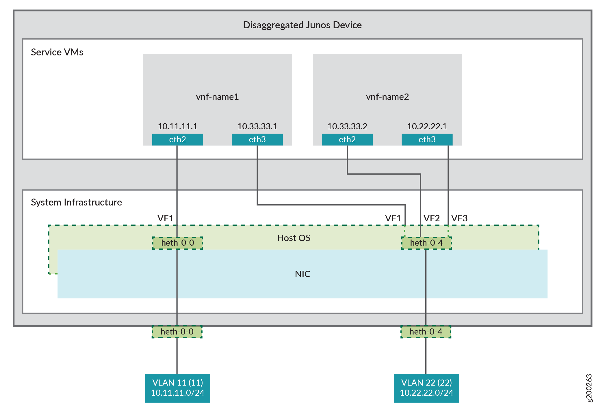
This example uses the front panel ports heth-0-0 and heth-0-4. The VMs use two interfaces each, eth2 and eth3.
These elements are generally separated into two parts: a LAN side and a WAN side.
As this example uses SR-IOV, the NIC ports’ virtual functions (VFs) are used to bypass the host OS and provide direct NIC-to-VM connectivity.
The key configuration elements include:
The front panel ports, heth-0-0 and heth-0-4.
The VNF interfaces. VNF interfaces must use the format eth#, where # is from 0 through 9.
The virtual function setting, to indicate SR-IOV is being used to provide direct access between the sxe and VNF interfaces.
Configuration
Creating the Service Chain
Step-by-Step Procedure
To configure the VNF interfaces and create the service chain:
Configure vnf-name1’s LAN-side interface as a Layer 3 interface, and map it to the LAN-side NIC interface. Include the virtual function (VF) setting to specify direct NIC-to-VM connectivity. VNF must use the interfaces from eth0 through eth9.
The heth interface is the configurable representation of the related NIC interface.
user@host> configure
[edit]
user@host# set virtual-network-functions vnf-name1 interfaces eth2 mapping heth-0-0 virtual-function
Configure the vnf-name1’s WAN-side interface from the eth3 VNF interface as shown in Figure 1.
user@host# set virtual-network-functions vnf-name1 interfaces eth3 mapping heth-0-4 virtual-function
Similarly bring up vnf-name2 with both interfaces eth2 and eth3 on heth-0-4.
user@host# set virtual-network-functions vnf-name2 interfaces eth2 mapping heth-0-4 virtual-function
user@host# set virtual-network-functions vnf-name2 interfaces eth3 mapping heth-0-4 virtual-function
Finally, configure the IP addresses and static routes for each interface of the VNFs, and add routes to achieve the complete bidirectional path for the service chain.