Example: Manually Configuring VXLANs on MX Series Routers
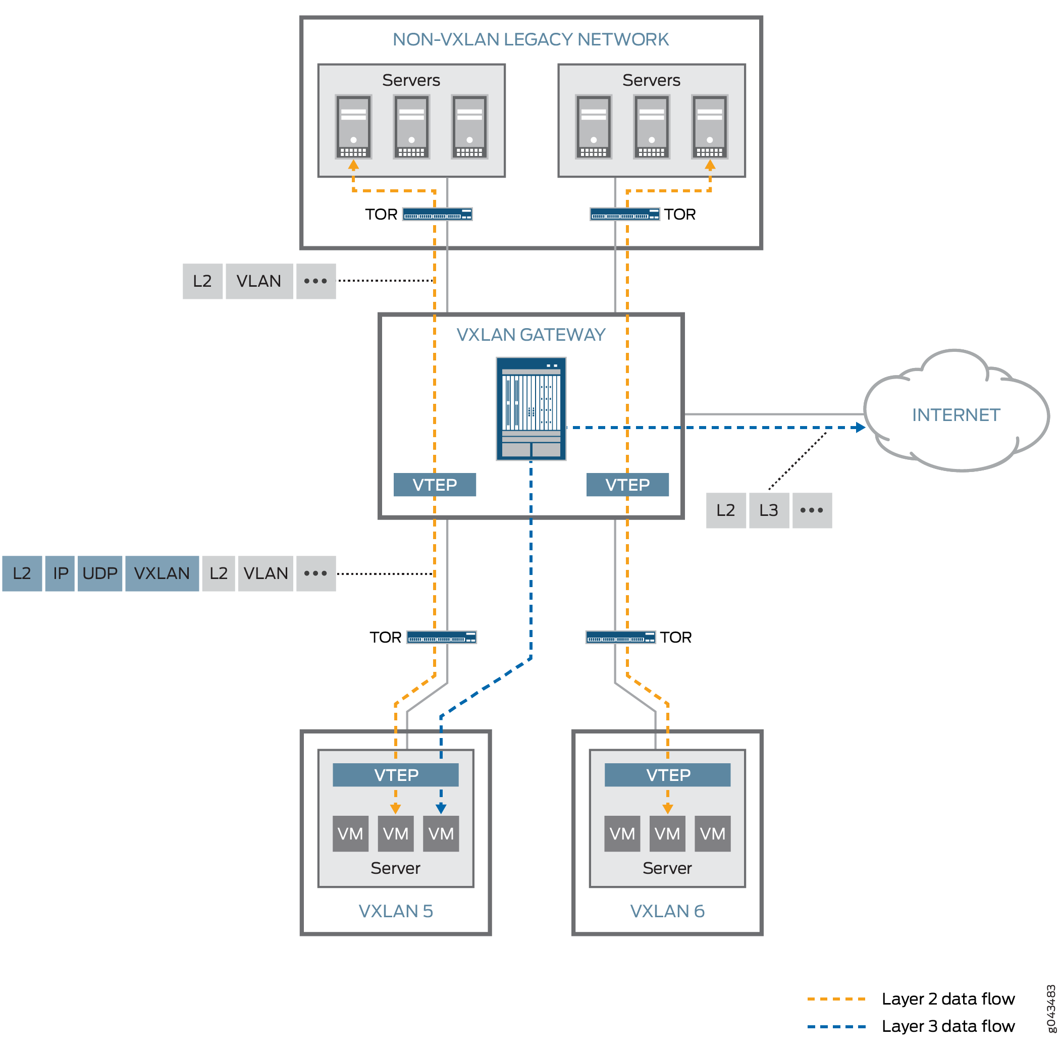
Virtual Extensible Local Area Network (VXLAN) is a Layer 3 encapsulation protocol that enables MX Series routers to push Layer 2 or Layer 3 packets through a VXLAN tunnel to a virtualized data center or the Internet. Communication is established between two virtual tunnel endpoints (VTEPs). VTEPs encapsulate the virtual machine traffic into a VXLAN header and strip off the encapsulation.
This example shows how to configure VXLAN on MX Series routers using switch options in a default bridge domain.
Requirements
This example uses the following hardware and software components:
An MX Series router
A VXLAN capable peer router
Junos OS Release 14.1
Overview
In this example, VXLAN is configured to run on a default bridge domain. VTEP interfaces sources are configured to the loopback address, and VLAN groups are configured under bridge domains with VXLAN enabled. Interfaces are configured for VLAN tagging and encapsulation, and IRB is enabled. OSPF and PIM protocols are configured to facilitate unicast and multicast routing. The chassis is configured for GRES and enhanced IP services.
We support static VXLAN and OVSDB-VXLAN with an IPv4 underlay. You configure the VTEP source interface as the loopback interface with an IPv4 address. We support an IPv6 underlay (the VTEP source interface as the loopback interface with an IPv6 address) only with EVPN-VXLAN configurations.
Topology
Configuring VXLAN on MX Series Routers
CLI Quick Configuration
To quickly configure this example, copy the
following commands, paste them into a text file, remove any line breaks,
change any details necessary to match your network configuration,
and then copy and paste the commands into the CLI at the [edit] hierarchy level.
set switch-options vtep-source-interface lo0.0
set bridge-domains vlan-5 vxlan vni 100
set bridge-domains vlan-5 vxlan multicast-group 233.252.0.1
set bridge-domains vlan-5 vlan-id 100
set bridge-domains vlan-5 routing-interface irb.0
set bridge-domains vlan-5 interface xe-1/0/0.0
set bridge-domains vlan-6 vxlan vni 200
set bridge-domains vlan-6 vxlan multicast-group 233.252.0.1
set bridge-domains vlan-6 vlan-id 200
set bridge-domains vlan-6 routing-interface irb.1
set bridge-domains vlan-6 interface xe-2/0/0.0
set interfaces xe-1/0/0 vlan-tagging
set interfaces xe-1/0/0 encapsulation flexible-ethernet-services
set interfaces xe-1/0/0 unit 0 encapsulation vlan-bridge
set interfaces xe-1/0/0 unit 0 vlan-id 100
set interfaces xe-2/0/0 vlan-tagging
set interfaces xe-2/0/0 encapsulation flexible-ethernet-services
set interfaces xe-2/0/0 unit 0 encapsulation vlan-bridge
set interfaces xe-2/0/0 unit 0 vlan-id 200
set interface irb unit 0 family inet address 10.5.5.1/24
set interface irb unit 1 family inet address 10.6.6.1/24
set interfaces lo0 unit 0 family inet address 10.3.3.3/32
set protocols ospf area 0.0.0.0 interface ge-8/3/8.0
set protocols ospf area 0.0.0.0 interface lo0.0
set protocols ospf area 0.0.0.0 interface xe-0/1/3.0
set protocols ospf area 0.0.0.0 interface ge-8/3/2.0
set protocols pim rp static address 10.2.1.3
set protocols pim interface lo0.0 mode bidirectional-sparse
set protocols pim interface ge-8/3/8.0 mode bidirectional-sparse
set protocols pim interface xe-0/1/3.0 mode bidirectional-sparse
set protocols pim interface ge-8/3/2.0 mode bidirectional-sparse
set chassis redundancy graceful-switchover
set chassis aggregated-devices ethernet device-count 10
set chassis fpc 1 pic 0 tunnel-services bandwidth 10g
set chassis network-services enhanced-ip
Configuring VXLAN
Step-by-Step Procedure
The following example show how to set up a basic VXLAN configuration with default bridge domains and switch options. To configure VXLAN on an MX Series router, follow these steps:
Configure VTEP interface sources under
switch-optionsfor the default-switch.[edit] user@router# set switch-options vtep-source-interface lo0.0
Set up a VLAN group named
vlan-5and set its VXLAN Network Identifier (VNI) to 100.[edit] user@router# set bridge-domains vlan-5 vxlan vni 100
Configure the
vlan-5multicast group address for VXLAN.[edit] user@router# set bridge-domains vlan-5 vxlan multicast-group 233.252.0.1
Set the VLAN ID to 100 for
vlan-5.[edit] user@router# set bridge-domains vlan-5 vlan-id 100
Configure integrated bridging and routing (IRB) for
vlan-5.[edit] user@router# set bridge-domains vlan-5 routing-interface irb.0
Assign the xe-1/0/0.0 interface to
vlan-5.[edit] user@router# set bridge-domains vlan-5 interface xe-1/0/0.0
Set up a VLAN group named
vlan-6and set its VXLAN Network Identifier (VNI) to 200.[edit] user@router# set bridge-domains vlan-6 vxlan vni 200
Configure the
vlan-6multicast group address for VXLAN.[edit] user@router# set bridge-domains vlan-6 vxlan multicast-group 233.252.0.1
Set the VLAN ID to 200 for
vlan-6.[edit] user@router# set bridge-domains vlan-6 vlan-id 200
Configure IRB for
vlan-6.[edit] user@router# set bridge-domains vlan-6 routing-interface irb.1
Assign the xe-2/0/0.0 interface to
vlan-6.[edit] user@router# set bridge-domains vlan-6 interface xe-2/0/0.0
Set up VLAN tagging for xe-1/0/0.
[edit]
user@router# set interfaces xe-1/0/0 vlan-tagging
Configure flexible Ethernet service encapsulation on xe-1/0/0.
[edit]
user@router# set interfaces xe-1/0/0 encapsulation flexible-ethernet-services
Set up VLAN bridging encapsulation for xe-1/0/0 unit 0˙.
[edit]
user@router# set interfaces xe-1/0/0 unit 0 encapsulation vlan-bridge
Set the xe-1/0/0 unit 0 VLAN ID to 100.
[edit]
user@router# set interfaces xe-1/0/0 unit 0 vlan-id 100
Configure VLAN tagging for xe-2/0/0
[edit]
user@router# set interfaces xe-2/0/0 vlan-tagging
Set up flexible Ethernet service encapsulation on xe-2/0/0.
[edit]
user@router# set interfaces xe-2/0/0 encapsulation flexible-ethernet-services
Configure VLAN bridging encapsulation for xe-2/0/0 unit 0˙.
[edit]
user@router# set interfaces xe-2/0/0 unit 0 encapsulation vlan-bridge
Set the xe-2/0/0 unit 0 VLAN ID to 200.
[edit]
user@router# set interfaces xe-2/0/0 unit 0 vlan-id 200
Configure the IRB unit 0 family inet address.
[edit]
user@router# set interface irb unit 0 family inet address 10.5.5.1/24
Configure the IRB unit 1 family inet address.
[edit]
user@router# set interface irb unit 1 family inet address 10.6.6.1/24
Set the family inet address for the loopback unit 0.
[edit]
user@router# set interfaces lo0 unit 0 family inet address 10.3.3.3/32
Set up OSPF for the ge-8/3/8.0 interface.
[edit]
user@router# set protocols ospf area 0.0.0.0 interface ge-8/3/8.0
Configure OSPF for the loopback interface.
[edit]
user@router# set protocols ospf area 0.0.0.0 interface lo0.0
Set up OSPF for the xe-0/1/3.0 interface.
[edit]
user@router# set protocols ospf area 0.0.0.0 interface xe-0/1/3.0
Configure OSPF for the ge-8/3/2.0 interface.
[edit]
user@router# set protocols ospf area 0.0.0.0 interface ge-8/3/2.0
Set up the static address for the protocol independent multicast (PIM) rendezvous point (RP).
[edit]
user@router# set protocols pim rp static address 10.2.1.3
Configure the loopback interface to bidirectional sparse mode for the PIM protocol.
[edit]
user@router# set protocols pim interface lo0.0 mode bidirectional-sparse
Set the ge-8/3/8.0 interface to bidirectional sparse mode for the PIM protocol.
[edit]
user@router# set protocols pim interface ge-8/3/8.0 mode bidirectional-sparse
Configure the xe-0/1/3.0 interface to bidirectional sparse mode for the PIM protocol.
[edit]
user@router# set protocols pim interface xe-0/1/3.0 mode bidirectional-sparse
Set the ge-8/3/2.0 interface to bidirectional sparse mode for the PIM protocol.
[edit]
user@router# set protocols pim interface ge-8/3/2.0 mode bidirectional-sparse
Configure redundant graceful switchover on the chassis.
[edit]
user@router# set chassis redundancy graceful-switchover
Set the aggregated ethernet device count to 10.
[edit]
user@router# set chassis aggregated-devices ethernet device-count 10
Configure the tunnel services bandwidth for FPC 1/PIC 0.
[edit]
user@router# set chassis fpc 1 pic 0 tunnel-services bandwidth 10g
Enable enhanced IP for network services on the chassis.
[edit]
user@router# set chassis network-services enhanced-ip
Results
From configuration mode, confirm your configuration by entering the following commands. If the output does not display the intended configuration, repeat the instructions in this example to correct the configuration.
user@router# show switch-options
switch-options {
    vtep-source-interface lo0.0;
}
user@router# show bridge-domains
bridge-domains {
    vlan-5 {
        vxlan {
            vni              100;
            multicast-group      233.252.0.1;
        }
        vlan-id              100;
        routing-interface    irb.0;
        interface            xe-1/0/0.0;
    }
    vlan-6 {
        vxlan {
            vni              200;
            multicast-group      233.252.0.1;
        }
        vlan-id              200;
        routing-interface    irb.1;
        interface            xe-2/0/0.0;
    }
}
user@router# show interfaces
interfaces {
    xe-1/0/0 {
        vlan-tagging;
        encapsulation flexible-ethernet-services;
        unit 0 {
            encapsulation vlan-bridge;
            vlan-id 100;
        }
    }
    xe-2/0/0 {
        vlan-tagging;
        encapsulation flexible-ethernet-services;
        unit 0 {
            encapsulation vlan-bridge;
            vlan-id 200;
        }
    }
    irb {
        unit 0 {
            family inet {
                address 10.5.5.1/24;
            }
        }
        unit 1 {
            family inet {
                address 10.6.6.1/24;
            }
        }
    }
    lo0 {
        unit 0 {
            family inet {
                address 10.3.3.3/32;
            }
        }
    }
}
user@router# show protocols ospf
area 0.0.0.0 {
    interface ge-8/3/8.0;
    interface lo0.0;
    interface xe-0/1/3.0;
    interface ge-8/3/2.0;
}
user@router# show protocols pim
rp {
    static {
        address 10.2.1.3;
    }
}
user@router# show chassis
redundancy {
    graceful-switchover;
}
aggregated-devices {
    ethernet {
        device-count 10;
    }
}
fpc 1 {
    pic 0 {
        tunnel-services {
            bandwidth 10g;
        }
    }
}
network-services enhanced-ip;
Verification
Confirm that the configuration is working properly.
Verifying Reachability
Purpose
Verify that the network is up and running with the proper interfaces and routes installed.
Action
user@router> show interfaces terse irb
Interface               Admin Link Proto    Local                 Remote
irb                     up    up
irb.0                   up    up   inet     10.5.5.1/24
                                   multiservice
irb.1                   up    up   inet     10.6.6.1/24
                                   multiservice

user@router> ping 10.5.5.1/24
PING 10.5.5.1 (10.5.5.1): 56 data bytes
64 bytes from 10.5.5.1: icmp_seq=0 ttl=64 time=0.965 ms
64 bytes from 10.5.5.1: icmp_seq=1 ttl=64 time=0.960 ms
64 bytes from 10.5.5.1: icmp_seq=2 ttl=64 time=0.940 ms
^C
--- 10.1.1.1 ping statistics ---
3 packets transmitted, 3 packets received, 0% packet loss
round-trip min/avg/max/stddev = 0.940/0.955/0.965/0.011 ms
Meaning
Use the show interfaces terse irb command
to verify that the IRB interface has been properly configured. The irb.0 and irb.1 interfaces should display the proper
multiservice inet addresses.
Use the ping command to confirm that the network
is connected to the IRB multiservice address.
Verifying VXLAN
Purpose
Verify that VXLAN is working and the proper protocols are enabled.
Action
user@router> show interfaces vtep
Physical interface: vtep, Enabled, Physical link is Up
  Interface index: 133, SNMP ifIndex: 575
  Type: Software-Pseudo, Link-level type: VxLAN-Tunnel-Endpoint, MTU: 1600, Speed: Unlimited
  Device flags   : Present Running
  Interface flags: SNMP-Traps
  Link type      : Full-Duplex
  Link flags     : None
  Last flapped   : Never
    Input packets : 0
    Output packets: 0

  Logical interface vtep.32768 (Index 334) (SNMP ifIndex 607)
    Flags: Up SNMP-Traps Encapsulation: ENET2
    VXLAN Endpoint Type: Source, VXLAN Endpoint Address: 10.255.187.32, L2 Routing Instance: default-switch, L3 Routing Instance: default
    Input packets : 0
Output packets: 0user@router> show l2-learning vxlan-tunnel-end-point remote mac-table
MAC flags (S -static MAC, D -dynamic MAC, L -locally learned, C -Control MAC
SE -Statistics enabled, NM -Non configured MAC, R -Remote PE MAC)
Logical system : <default>
Routing instance : default-switch
Bridging domain : vlan-5+100, VLAN : 100, VNID : 100
Bridging domain : vlan-6+200, VLAN : 200, VNID : 200user@router> show l2-learning vxlan-tunnel-end-point source
Logical System Name Id SVTEP-IP IFL L3-Idx
<default> 0 10.255.187.32 lo0.0 0
L2-RTT Bridge Domain VNID MC-Group-IP
default-switch vlan-5+100 100 233.252.0.1
default-switch vlan-6+200 200 233.252.0.1 Meaning
Use the show interface vtep command to displays
information about VXLAN endpoint configuration. Make sure the routing
instance is assigned to the default-switch..
Use the show l2-learning vxlan-tunnel-end-point remote
mac-table command to confirm that the bridging domain VLAN groups
were configured correctly.
Use the show l2-learning vxlan-tunnel-end-point source command to confirm the multicast IP addresses for bridging domain
VLAN groups.