Use Case and Reference Architecture
Before we go deeper into the integration, we must review how the fabric usually operates and forwards Packets. It is critical to understand how a Layer 2 (L2) VLAN at an Access-Switch of the fabric, where Wired and Wireless Client are connected to, makes its way to other VLANs with Clients and forward and also via the WAN router towards internet.
Basic Forwarding Operation of a Fabric
Without corner cases like the seldom used Bridged-Overlay-option it can be assumed that all VLANs of a fabric are connected to at least one global Virtual Routing Function (VRF). Most customers use a handful of multiple VRFs. By design:
- The fabric VRF will contain the IP address as Gateway for each attached VLAN Client at Access Switch. The Wired Client needs to know and send Traffic to that IP address if he wants to leave the fabric or communicate with any other VLAN in the fabric. This can be a static assignment on the Client side, or he obtains this information via a DHCP-Lease.
- VLAN’s that are connected to the same VRF can talk directly to each other and exchange Traffic. This type of East-West Traffic is always handled directly in the fabric. If the Traffic needs to be controlled inside a VRF then typically ACLs or, if the fabric supports it, VXLAN Group Based Policies can be used deployed on the Access Switch.
- VRF’s are ALWAYS isolated! This is a security measurement by Design. As a result, all Traffic between VRF’s need to go up to the WAN router for security screening. Should the WAN router then permit this Traffic then it will be sent back to the next VRF to the fabric. So, one always enforces North-South Traffic this way.
Virtual Gateway Fabric Versus Anycast Fabric
Depending on the fabric Type the Overlay VLAN’s, where the Client Traffic is in, may need additional IP addresses for internal proposals, which is the case for Virtual Gateway Fabrics. Mist Campus Fabrics configures the following fabric Types:
| Fabric Type | Virtual Gateway Fabric | Anycast Fabric |
|---|---|---|
| EVPN Multihoming Fabric | Yes | --- |
| Central Routed and Bridged Fabric (CRB) | Yes | --- |
| Edge Routed and Bridged Fabric (ERB) | --- | Yes |
| IP-Clos Fabric | --- | Yes |
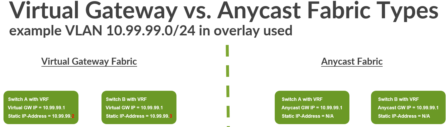
In a Virtual Gateway Fabric, you typically have a very limited amount of VRF’s located in the fabric. Those are located at the Core or Collapsed Core Switches. As the maximum supported amount of Core/Collapsed Core Switches in a Mist Campus Fabric can manage is four. This also means a certain VRF can be duplicated to each redundant Core/Collapsed-Core Switch maximum four times in the fabric. Anycast Fabrics, however, are designed for more scale out designs hence the location of the VRFs is either on the Distribution Switch (ERB) or in fact even at the Access Switch (IP-Clos). The nature of all Virtual Gateway Fabrics is however that the system also assigns for every VLAN located in the fabric an additional static IP address that is unique per VRF. Hence apart from the Gateway IP address of the gateway for a VLAN you need in each subnet up to four additional IP addresses as the maximum number Core/Collapsed Core Switches in a Mist Campus Fabric is 4.
Why such a design? Well, there are benefits for certain Traffic of the fabric, for example, when doing DHCP-Relay. For DHCP-Relay the system uses the static IP address instead of the Gateway IP address when forwarding the DHCP-Client requests from a certain VRF. This behavior will ensure that the returned answer will be send back straight to the concerned VRF as the static IP address is unique to the VLAN/Core-Switch (with VRF).
Another way to think about a Virtual Gateway Fabric is if you compare it with traditional L2 Gateway failover designs such as VRRP. There you always have a VIP which floats between the Gateways (that are our VRF’s) and each Gateway always needs an additional unique static IP only he has in that VLAN. In a Mist Campus Fabric there is naturally no VRRP protocol ever spoken or needed as the EVPN control plane takes over for it.
This small sacrifice needing to plan room for those additional static IP addresses in each VLAN is eliminated in Anycast Fabrics. This is because the more scale out Distribution/Access Switches where VRFs are installed you would have to plan your future growth well when creating VLANs. System services such as DHCP-Relay work in Anycast Fabrics a bit differently and are internally more complex.
When creating a new VLAN, the fabric gateway IP address is the lowest host IP address of a subnet. In case of a virtual gateway fabric, the maximum 4 additional static IP addresses needed are usually increments of that lowest host IP address of a subnet. As a best practice doing manual changes to the gateway IP addresses and static IP addresses should be avoided. Changing those addresses only adds confusion when others might also manage the fabric.
Service Block Function of a Fabric
When designing the connection of the fabric to the WAN router, you will leverage a so-called service block function. You may also find the terms service leaf or border leaf used in other literature. The service block function is meant for all kind of integration scenarios such as:
- WAN router integration in a fabric.
- Server attachment for any kind of local services your fabric
needs to provide such as:
- DHCP server for fabric VLANs.
- File services
- Webservers
- Mist edge for wireless network overlay
- Many more services
- All kinds of migration scenarios with legacy fabrics and network designs
A service block function in a Mist Fabric can be either virtual or physical depending on the design of the fabric.
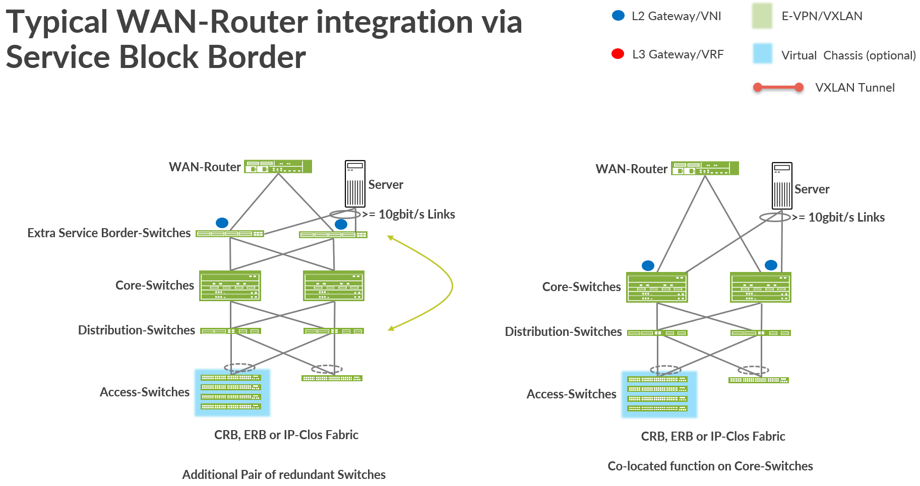
- A virtual service block function is a co-located function that is usually added to a fabric node that usually has a different function. In our case that means that the Service block function is added to the Core-Switches of the fabric. This is the default design that enables you to deploy a fabric with minimal Hardware footprint.
- A physical Service block function is always consistent of a pair of dedicated Switches on-top of the Core-Switches of a fabric deployed. You can think of those as a pair of dedicated Distribution Switches swapped northbound of the fabric. Hence it is also recommended to use similar Hardware as your distribution Switches have.
The picture below shows both designs where the physical service block function is on the left and the virtual service block function is on the right side of the picture.
When deploying fabric, it’s typically the scale, local port or interface usage, and port speed and density of the core switches that influence the decision between using a virtual or a physical switch deployment. We recommend that you consider the following:
- Apart from the WAN routers do you have enough ports left for future server attachment?
- Do the supported port speeds match with what you want to attach?
- Can a physical service block function present a scale limit in the future?
- The speed of the connected WAN router. Remember that all VRF-to-VRF traffic must go through the WAN router by design.
When the fabric grows in the future to more than two core switches use then you must have a dedicated pair of physical service block switches for the service block function.
WAN Router Integration Using Service Block Function
There are several ways one can attach a fabric to the WAN router for traffic towards the internet. Usually, one determines them by the way you attach the WAN router to the service block function of the fabric.
You can attach the WAN router:
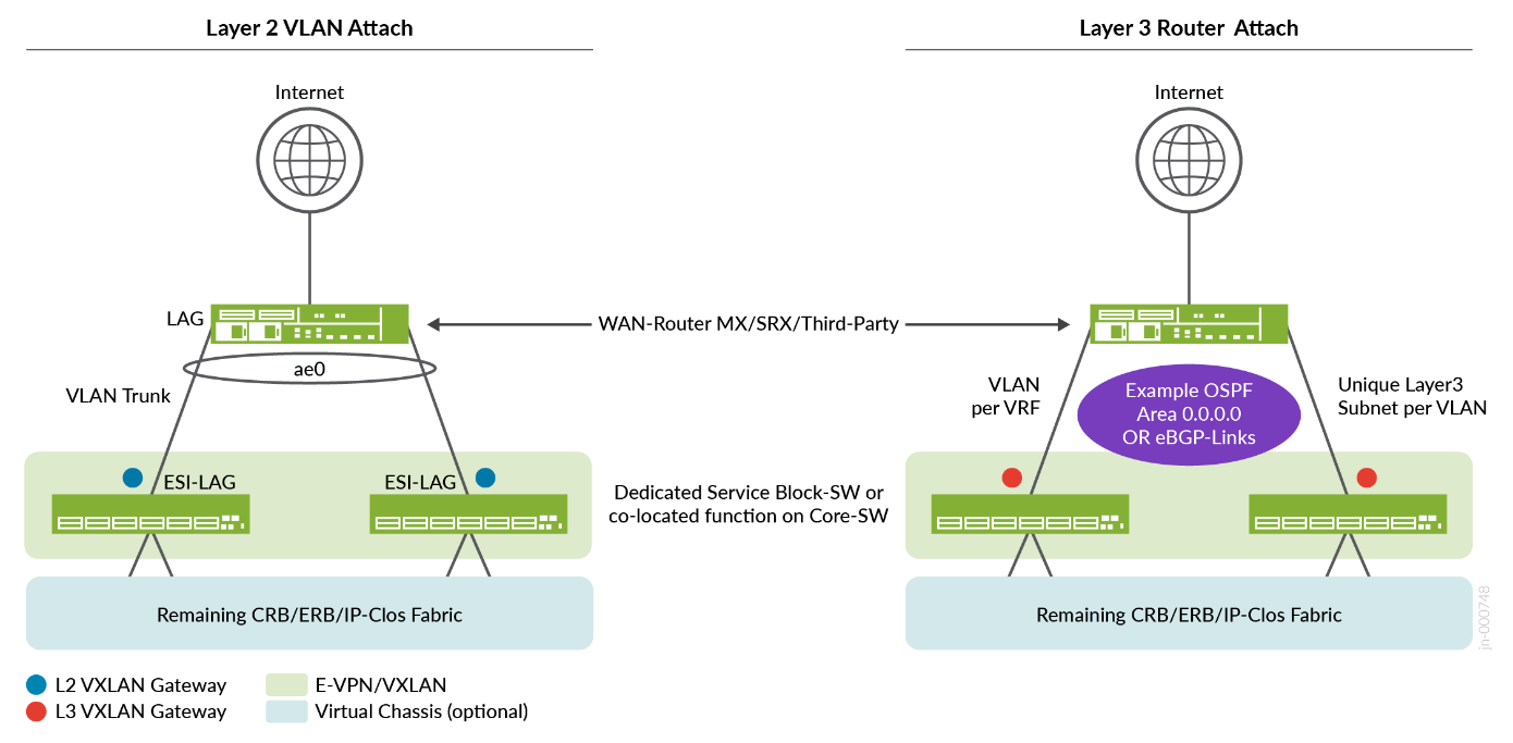
- Using an L2 Method:
- VLAN’s seen on the access layer of a VRF or additional defined transport VLAN’s attached to VRF will be shared via a Trunk-Interface towards WAN router.
- The trunk links between the service block function of the fabric and WAN router must use IEEE 803.2ad LAG/LACP to be able to detect link-failures and missing devices. You can NOT use STP here. On the service block function of the fabric, you will configure an ESI-LAG to achieve this. The WAN router side just needs a standard IEEE 803.2ad LAG/LACP configuration with active Link management. Should the latter not be supported by the vendor of the WAN router then consider a Layer 3-Method instead.
- In the Fabric dialogue for each VRF one must configure a manual Route with a static IP address for all default Traffic towards the Internet and other VRF’s. This static IP address is then reachable via the WAN router.
- WAN router needs to have this static IP address assigned to an interface towards service block function of the fabric for reachability. Redundancy of this static IP address needs to be achieved by means of an L2 Gateway redundancy Protocol. The usage of VRRP is highly recommended here and the static IP address is then the VIP.
- On WAN router you may have to define an additional static Route for the VLAN’s attached to a VRF.
- Using an L3 Method:
- The links between the service block function of the fabric and WAN router will be defined as L3 P2P-Links with IP addresses. Those will need to be individually configured on each service block function of the fabric and opposite WAN router.
- Each P2P Link will need to be assigned to a VLAN-Name that is ALSO assigned to the VRF of the fabric. Via this indirect linking the Mist Cloud can reference and bind a particular VRF to the Link. Additionally, the VLAN-ID assigned to the P2P Link provides isolation against other VRF’s on the same Link.
- In the Fabric dialogue for each VRF you do NOT need to configure any additional Route towards WAN router as the fabric gets this information from the WAN router via a supported Routing protocol.
- You have to set up and create policies for import and exporting routes between fabric and WAN router.
- You must use a L3 Routing Protocol to establish the
route-exchange and forwarding between the fabric and WAN router.
Supported as of today are:
- Exterior BGP, which is fully UI, driven.
- OSPF (Policies for im/export of Routes are today still needing additional CLI).
RECOMMENDED is using the L3 eBGP based method wherever this is technically possible from the first day on. Even if it is initially a higher effort to configure, it will be the only method in the future to achieve new features such as DCI.
L2 WAN Router Attach Details
L2 WAN router attachment methods should only be chosen in Lab-designs or small fabrics. Even then if you design an HA/Redundant WAN router design the WAN router vendor MUST support IEEE 803.2ad LAG/LACP AND a redundant L2 Gateway Method such as VRRP. Without the two supported you won’t be able to achieve a HA/Redundant WAN router design that does not fail at some point.
If you use an L2 method, you have the following options:
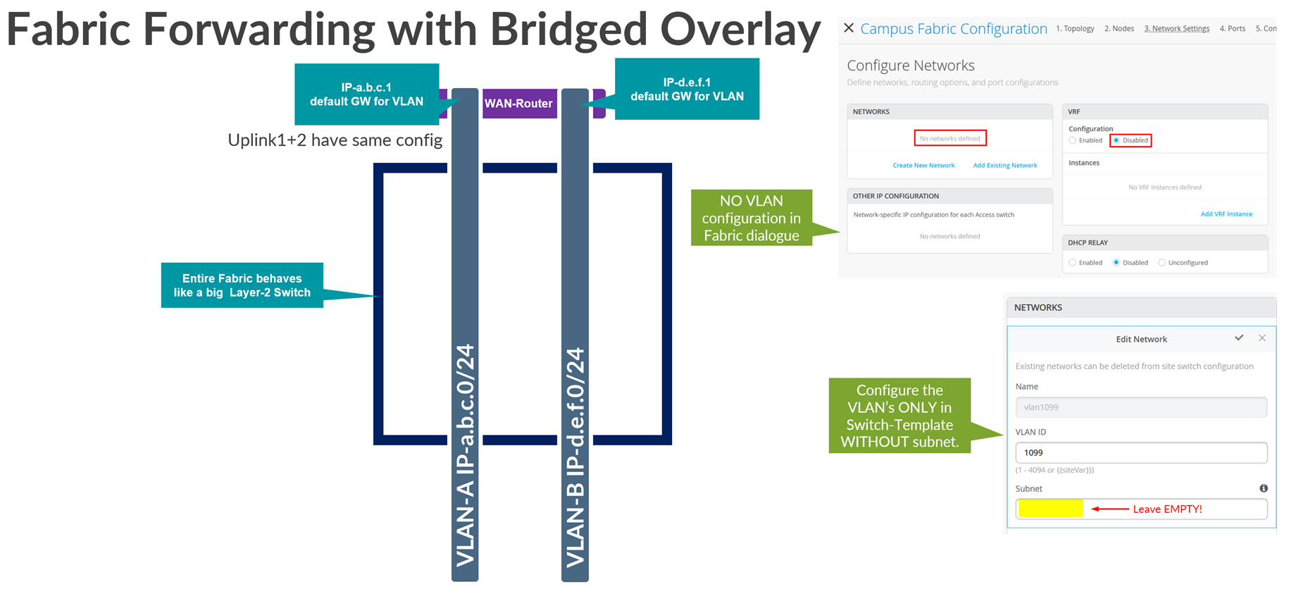
- Treat the entire fabric as a big L2 Switch and use the Bridged Overlay model.
- Strech at least one VLAN from Access Switch side also to the WAN router and that the WAN router an IP address in that VLAN is then the Default-GW for the VRF itself. (Do not use for production.)
- Define a dedicated Transport VLAN for each VRF. (Recommended when doing L2 exit.)
The bridged overlay model allows you to handle all the Layer 3 (L3) gateway functions of a VLAN directly on the WAN router itself. Many technical drawbacks might prevent you from using certain features of the fabric. If you want to migrate directly from a legacy design, you can use the bridged overlay model, so we describe the uses and benefits of that model here:
- There are no VRF configured anywhere in the fabric. Therefore, the fabric acts like a large, distributed L2 switch.
- All traffic is anchored outside of the fabric at the external WAN router.
- WAN router must play the role of the GW in each VLAN.
- VLANs can only talk to each other VIA the WAN router. Hence any East-West Traffic is always enforced to go up to the WAN router first for any VLAN to VLAN Traffic.
- All VLANs you are using on any Access Port of the fabric have to be also configured on the Uplink Ports towards WAN router.
The following lists the known limitations of the bridged overlay approach:
- There is a limit of around 250 VLANs you can use with this approach. This is mainly because the WAN router cannot provide more than 250 VRRP groups for gateway failover. You can confirm this with the WAN router vendor.
- If DHCP relay is required, then it must be configured on the WAN router.
- This model allows the WAN router to be the DHCP server for your VLANs. However, it also means that you must configure DHCP lease redundancy between two WAN routers when those WAN routers are deployed as an HA pair.
- All East-West inter-VLAN traffic on the fabric must flow through the WAN router.
-
When implementing bridge overlay in an IP Clos fabric, some features may be lost. Since inter-VLAN traffic is always forced to exit the fabric—and VXLAN headers are stripped before reaching the WAN router—Group-Based Policies (GBP) become limited in functionality. As a result, GBP can only control or block traffic between clients within the same VLAN. It is not possible to manage traffic between clients in different VLANs, even if they belong to the same VRF.
A combination of the bridged overlay method and some other method to achieve a hybrid design is technically possible. Such a combination is often used when customers decide to provide a separate path (VLAN) for guest access that must not interfere with the fabric VLANs used for regular clients.
Let’s now review the other two most commonly used L2 models:
-
Stretched VLAN: This is the method used in
labs to make fast progress when attaching WAN routers; where the
goal is not to provide a production-grade design but rather
something simple and easy to debug. You see this method commonly
used in Juniper JVDs and NCEs as an example.
- Using this method, a VLAN within a VRF instance that is used in access switches will also be used on the uplink to the WAN router, between the service block function and the WAN router.
- As a result of this stretched VLAN, the WAN router must be assigned a free IP address on that VLAN and the manual route for the default GW in the VRF configuration will point to that IP address.
- You can attach more VLANs to that VRF if needed. But you must delete or modify the VLAN used for the stretch to the WAN router.
- Do not use the stretched VLAN method in production environments. It has some downsides such as when a packet might need to be hair-pinned inside the fabric because of sub-optimal routing within the fabric.
-
Transport VLAN: This is the method recommended
for use in a production-grade design when using an L2 attachment
method.
- Using this method, a dedicated VLAN per VRF or WAN router must be used on the uplink to the WAN router between the service block function and the WAN router. This dedicated VLAN is not used on any access switch within the fabric.
- The WAN router is assigned a free IP address on that dedicated VLAN and the manual route for the default GW in the VRF configuration points to that IP address.
- In this case, it is assumed that you have one or more other VLANs that you use on the access switches for that VRF.
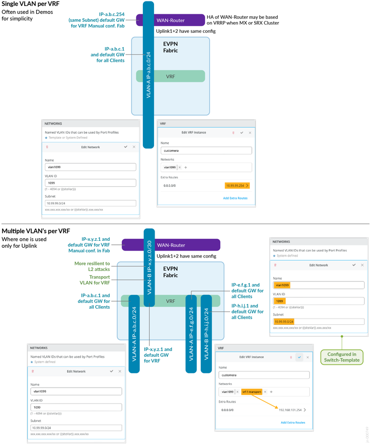
Going deeper into the forwarding and configuration of a stretched VLAN:
- On the service block border function, you create an ESI-LAG that contains all stretched VLANs that belong to the fabric (one per VRF).
- The WAN router only needs ordinary LAG support because with the stretched VLAN, you pool the links towards the attached service block border switches in a single LAG configuration.
- For example, on the VLAN 10.99.99.0/24, the fabric VRF might have the anycast or virtual GW IP address 10.99.99.1. This address will be used by all wired and wireless clients to send traffic to the fabric.
- In the VRF we configure a default route (0.0.0.0/0) with a gateway of 10.99.99.254
- The IP address 10.99.99.254 is then configured at vlan 1099 on the WAN router providing the forwarding for the fabric.
- If you have redundant WAN routers, then configure a VRRP-VIP with the address 10.99.99.254 on them.
Going deeper into the forwarding and configuration of a transport VLAN:
- Define additional transport VLANs in your switch template. Just define a VLAN-ID with no network information.
- In your fabric definition, exclude the transport VLANs in the VRF they should use. Only add the access VLANs there.
- Do not define a default route in the fabric VRFs. The default route gets configured in the service block definition.
- On the service block border switch, add the local IP address of the network for the VLAN, such as 192.168.101.1/24, using the additional IP address configuration.
- On the Service block border switch, create an ESI-LAG that contains only the chosen transport VLAN of each VRF.
- The WAN router only needs ordinary LAG support because you pool the links to the attached service block border switches in a single LAG configuration.
- You then need to manually create and edit the VRF service block
border switch
- Add your transport VLAN to the access-VLANs that automatically appear.
- Create a default a route (0.0.0.0/0) with a gateway of 192.168.101.1.254
- For a VLAN such as 10.99.99.0/24 the access or fabric VRF will have the Anycast/virtual GW IP address which is in this case the 10.99.99.1. This will be used by Wired/Wireless Clients.
- The IP address 192.168.101.254 then is configured at vlan 101 on the WAN router providing the forwarding of the fabric.
- The WAN router must also configure a static route towards 10.99.99.0/24 via 192.168.101.1 as that is the Link to the VRF of the fabric.
- Should you have redundant WAN routers then configure VRRP-VIP for 192.168.101.254 on them.
- Finally, it is also recommended, using additional CLI at this
point in time, that you change the transport VLANs and VRF’s
on the service block function into Virtual Gateway addressing
independent of the fabric type! This will warrant that the Traffic
will flow in the optimal Way. Should you forget to make this
improvement there may be situations happening where Traffic
unnecessary hairpins twice your service block functions via the
below distribution Switch. The situation happens in the following
example when:
- A packet leaves the fabric out on service block function 1 via uplink1 as anchor-point for the ESI-LAG.
- A WAN router gets the packet on uplink1 but sends the answer packet down to uplink2 towards service block function 2.
- Service block function 2 sees that the anchor point was service block function 1 but has no direct link to it. So, it sends the answer packet down to a distribution switch.
- The distribution switch forwards the packet back up to the service block function 1.
- The service block function 1 then as anchor point forwards the answer to one of the distribution switches as it should be under normal conditions.
When we make the suggested change, this additional hair-pinning of traffic is avoided. Please see more how this is achieved in the appendix section below where we share concrete examples.
A common error is that people forget to sync the AE-Index-Field when defining the uplinks on the two service block functions of the fabric. The same values must be chosen on both service block function interfaces. The system does not check this and does not warn you if the fabric uses it elsewhere. Also, make sure to enable the esilag configuration knob.
L3 WAN Router Attach Details
Finally, let’s review the more robust and scalable L3 methods of attaching a WAN router to a fabric. When you use an L3 method, you have the following options:
- Use OSPF as the routing protocol between the fabric and the WAN router.
- Use exterior BGP as the routing protocol between the fabric and the WAN router. In this case, we just exchange routes, not EVPN information.
WAN Router Integration Using L3 Router Attach:
- This method does not work if you have disabled VRFs. You need at least one VRF.
- Between the WAN router and the service block functions you need
a routing protocol to deal with failovers in case of a lost link.
You can choose between OSPF or eBGP:
- OSPF may be simpler to configure but needs some additional CLI for the added route filters.
- eBGP allows you to configure everything in the GUI but it is a bit more complex. This is the Juniper recommended method of attaching a WAN router to a fabric.
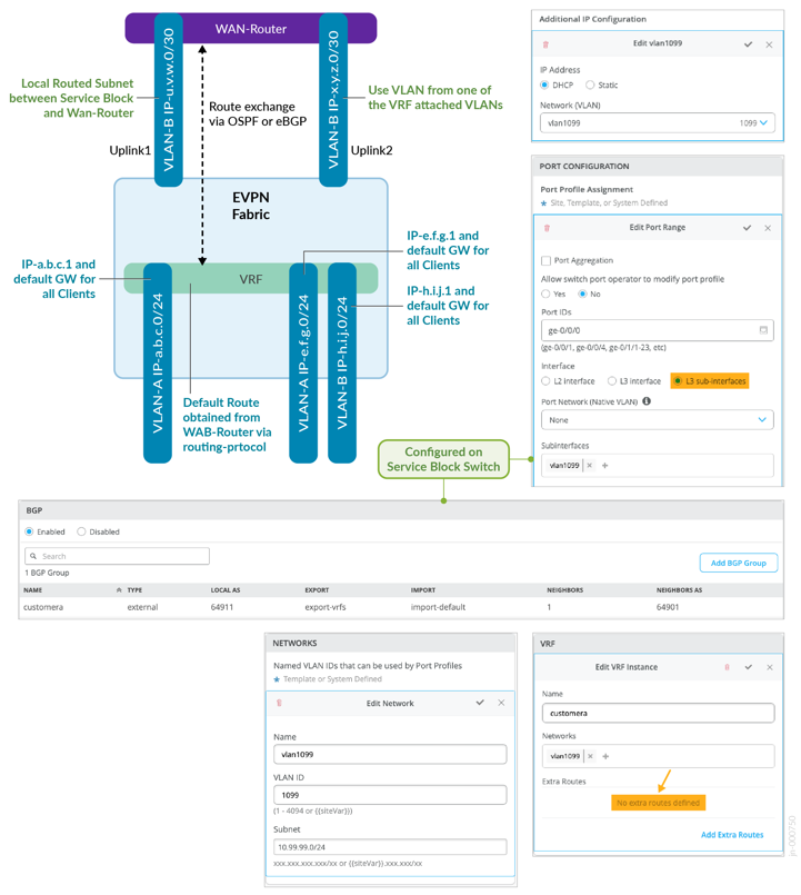
- In the fabric dialogue there is no need to manually define additional routes per VRF since those will be obtained via OSPF or eBGP.
- For each VRF, select one of the existing attached VLANs to act as the uplink towards the WAN router as indirect mapping towards the VRF. In a production-grade, highly available environment, you have two WAN routers. You must have at least two VLAN’s in each VRF before you can attach your WAN routers. This may be a bit strange but when referencing a VLAN that is bound to a VRF, the Mist UI knows how to reference the VRF. If you want, you can use device-transport VLANs per VRF, but you always need two as we expect a pair of redundant WAN routers for production.
- For each uplink VLAN (representing a VRF) you must have an IP subnet for L3 point-to-point (P2P) communication. Those subnets must be unique and non-overlapping with the pool the fabric uses (usually 10.255.240.0/20). You can choose them on your own since you need to manage that assignment manually. It may seem strange that you overwrite the IP addresses of the fabric VLAN in the sub-interface definition, but this is by design. For the P2P links, we recommend using /31 networks outside of the fabric range mentioned above.
- While most of the configuration can be done in the Mist GUI,
you must provide a few lines of additional CLI for OSPF:
- This is to provide needed policy statements for the import and export filters for the OSPF area for each VRF. With eBGP you can manage those filters in the Mist GUI.
- You also need to set a unique OSPF router ID for each VRF. This is to ensure that routes from the WAN router (such as the default route) are imported into each fabric VRF individually.
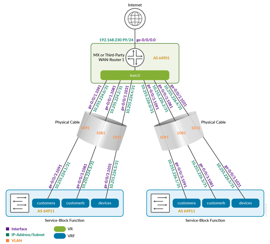
- When choosing eBGP you must manage your own private Autonomous System Numbers (ASN). The Mist fabric starts with the ASN 65000 so you must choose and ASN lower than that. We do not recommend the use of a unique AS per VRF because the maximum number of local ASN on a QFX swich is 16. We recommend that you use a shared ASN among your VRFs.
All L3 methods per VRF and WAN router on the uplink for the P2P links are multiplexed into each link. In a production-grade design you would expect to have two WAN routers. This means that each VRF needs a minimum of two VLANs to make the connection to the outside.
Figure 3 shows an example of an eBGP configuration for two service block functions and a single WAN router.
We have provided configuration examples for all the WAN router attach methods in the appendix. If something is unclear, check the appendix.