Appendix: Building the Topology and Testing Environment
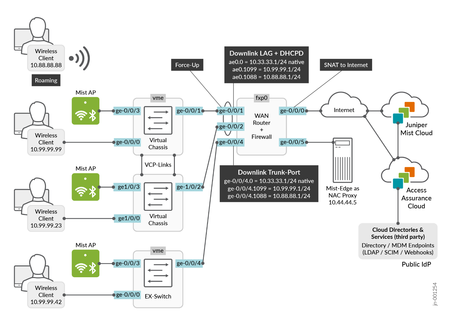
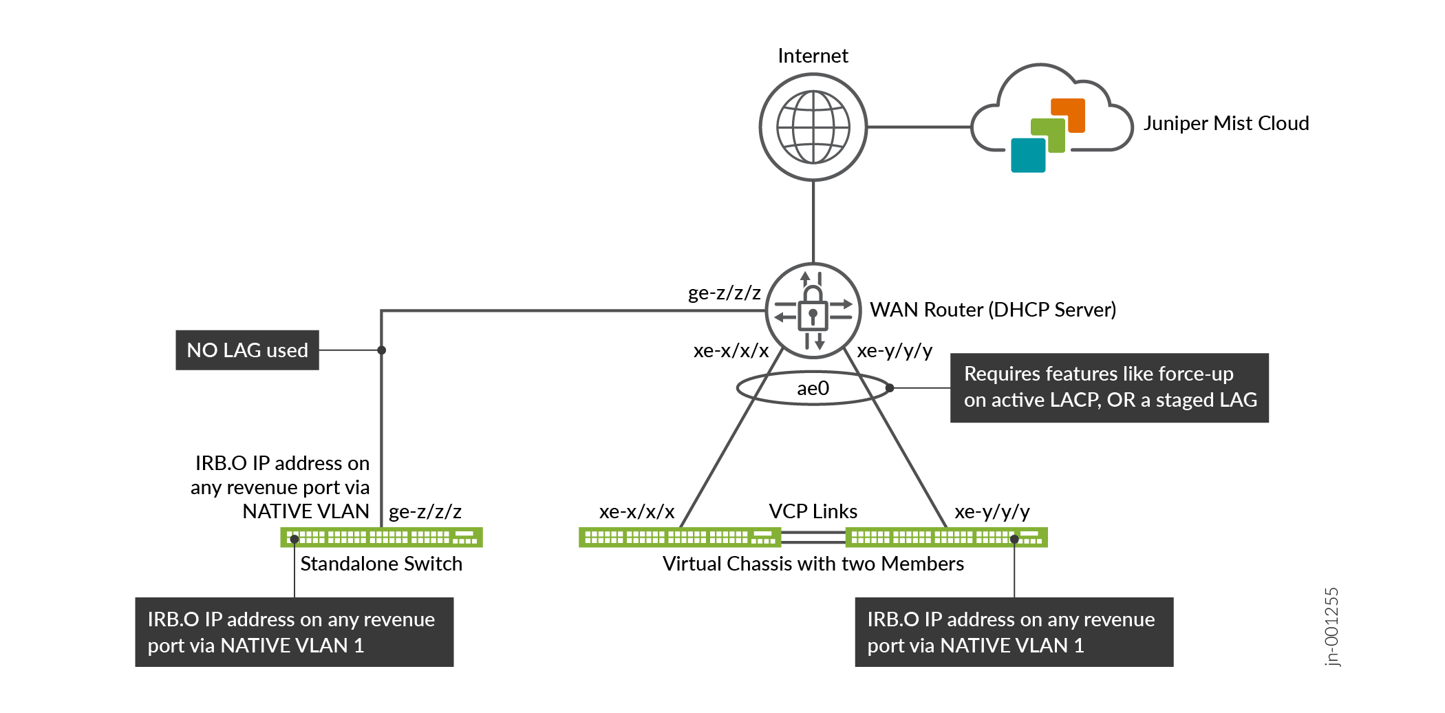
In this appendix, we share information on how you can repeat the test cases that were executed for this JVD. The Figure 1 configuration allows you to repeat all test cases for Access Assurance as long as you have the required minimal devices needed:
- A WAN router
- Default gateway for all VLANs
- DHCP server for all VLANs
- Has at least one WAN connection towards the Internet where the Juniper Mist cloud and Juniper Mist authentication cloud is.
- Has a VPN to a headquarters or uses local breakout of the traffic (as in our case).
- Can define trunk ports with a native VLAN for inline management of attached switches and APs.
- Optional: Trunk ports may use 802.3ad link aggregation with active LACP and the force-up option.
- A Standalone Switch
- PoE support to power attached APs
- Use a single uplink towards the WAN router
- Optional: A Virtual Chassis
- Minimum two members for testing
- PoE support to power attached APs
- Use a LAG towards the WAN router
- Juniper APs
- Powered using PoE from the switch.
- Two or more at different switches to test roaming
- Optional: Juniper Mist Edge appliance
- For this lab, directly attached to the local WAN router and not located remotely in a headquarters
- Mist authentication configuration for customer PKI
- Wired and Wireless clients to be tested
- Make sure they support 801.1X EAP supplicants for the authentication method you want to test
- Certificate management of these clients is not within the scope of Access Assurance. Customers can use an MDM or manual deployment
We are using four VLANs in this configuration for the minimally required functional design:
- VLAN1033 with the subnet range 10.33.33.0/24 is a native VLAN that is used for in-band management of the attached switches and APs.
- VLAN1099 with the subnet range 10.99.99.0/24 is used as a VLAN for attached wired clients.
- VLAN1088 with the subnet range 10.88.88.0/24 is used as a VLAN for attached WLAN clients.
- VLAN1044 with the subnet range 10.44.44.0/24 is used as a VLAN for the Juniper Mist Edge appliance.
All of these VLANs use the WAN router as the default gateway with the IP address 10.x.y.1 assigned to it, which also hands out DHCP lease to clients.
VLAN1033 is getting treated as VLAN1 on the switch and AP. This is because the default VLAN on all Juniper switches is VLAN1 and is the access/native VLAN on all revenue ports.
The recommended workflow for building such a lab is:
- Deploy the WAN router and install
- Deploy switches and Virtual Chassis and install
- Deploy APs and install
- OPTIONAL: Deploy Juniper Mist Edge and install
- Juniper Mist authentication cloud certificate installation
- Configure the client supplicants with certificates and the necessary EAP methods
WAN Router Installation and Configuration (Example for Branch Design)
In this chapter, we share configuration examples when using a Juniper Networks® SRX Series Firewalls as WAN router that is also managed by the Juniper Mist cloud in a simple branch design. Such a solution is called a “full stack” solution as it enables you to manage all network devices located at a branch site within a single pane of glass.
If you have deployed a Juniper campus fabric, you can skip this chapter now as in most cases it does not apply to you. In most campus fabric designs, Layer 2 VLANs are terminated inside the fabric itself, and the WAN router oversees handling route forwarding Layer 3 information. The following JVD extension provides the information about WAN Router Integration into Campus Fabrics.
Make sure the SRX device has an AppID license or else it cannot be managed by the Juniper Mist cloud. This is independent of whether you use it as a standalone firewall or as an SD-WAN router managing your VPN.
The following list of steps summarizes the process used to configure the WAN router in this chapter and is immediately followed by a detailed description of those steps:
- Define custom applications that present the destination IP ranges for internet and LAN segments.
- Define networks and VLANs
- Build a WAN Edge template describing:
- WAN interfaces and their configuration
- LAN interfaces and their configuration:
- Default gateways for each network.
- DHCP server settings for each network.
- Binding of networks to interfaces along with possible LAG configurations.
- Define traffic steering paths
- Define application policies
- Optional: Add additional Junos OS CLI commands
- Assign the template to sites
- Onboard a WAN Edge device and assign it to a site
- Check the configuration and status of the new WAN router
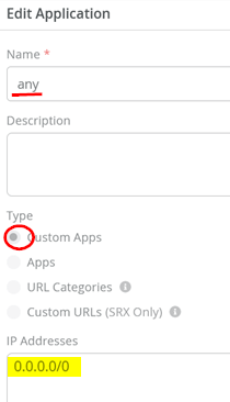
Go to Organization > Applications and check that there is an existing application with the following settings:
- Name=
any - Type=
Custom Apps - IP Addresses=
0.0.0.0/0
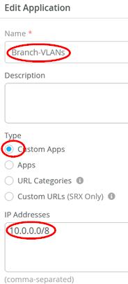
Add another application with the following settings:
- Name=
Branch-VLANs - Type=
Custom Apps - IP Addresses=
10.0.0.0/8
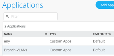
You should now see the two applications listed as shown below:
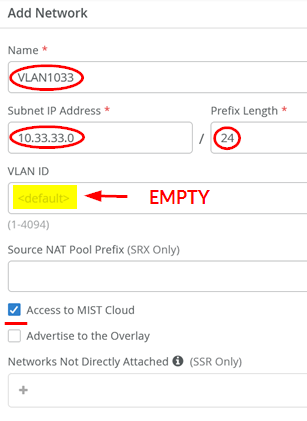
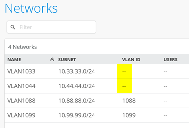
Go to Organization > Networks and add the first VLAN which is used to manage switches and APs:
- Name=
VLAN1033 - Subnet IP Address=
10.33.33.0 - Prefix Length=
24 - VLAN ID=
Leave this field empty. (This is the native VLAN used for in-band management of the attached EX Series Switch as well as the AP). - Access to Mist Cloud=
Enabled. (This must be enabled for the attached switches and AP to be managed by the Juniper Mist cloud).
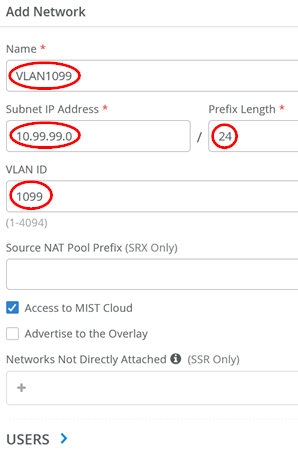
Then, add the second VLAN (in our topology we use this for wired clients):
- Name=
VLAN1099 - Subnet IP Address=
10.99.99.0 - Prefix Length=
24 - VLAN ID=
1099
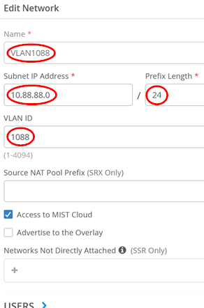
Then, add the third VLAN (in our topology, we use it for wireless clients attached to APs)
- Name=
VLAN1088 - Subnet IP Address=
10.88.88.0 - Prefix Length=
24 - VLAN ID=
1088
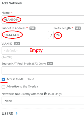
Add the last VLAN (in our topology, we use it for accessing the Juniper Mist Edge device’s out-of-band management port)
- Name=
VLAN1044 - Subnet IP Address=
10.44.44.0 - Prefix Length=
24 - VLAN ID=Leave this field empty. This is the native VLAN used towards the Juniper Mist Edge.
- Access to Juniper Mist cloud=
Enabled. This must be enabled for the attached switches and AP to be managed by the Juniper Mist cloud.
Review the four networks and verify that no VLAN ID is set for the switch and AP management network and the Juniper Mist Edge attach, since this is a native VLAN on the downlink trunk.
The following JSON template may be used to configure the branch WAN router. Alternatively, manual configuration steps for the branch WAN router are listed immediately after the JSON template.
{
  "type": "standalone",
  "port_config": {
    "ge-0/0/0": {
      "usage": "wan",
      "name": "wan",
      "ip_config": {
        "type": "dhcp"
      }
    },
    "ge-0/0/15": {
      "usage": "wan",
      "name": "wan2",
      "ip_config": {
        "type": "dhcp"
      }
    },
    "cl-1/0/0": {
      "usage": "wan",
      "name": "lte",
      "wan_type": "lte",
      "ip_config": {
        "type": "dhcp"
      }
    },
    "ge-0/0/1-2": {
      "networks": [
        "VLAN1033",
        "VLAN1099",
        "VLAN1088"
      ],
      "usage": "lan",
      "aggregated": true,
      "ae_disable_lacp": false,
      "ae_lacp_force_up": true,
      "ae_idx": 0,
      "redundant": false,
      "critical": false,
      "disabled": false
    },
    "ge-0/0/4": {
      "networks": [
        "VLAN1033",
        "VLAN1088",
        "VLAN1099"
      ],
      "usage": "lan",
      "aggregated": false,
      "redundant": false,
      "critical": false,
      "disabled": false
    },
    "ge-0/0/5": {
      "networks": [
        "VLAN1044"
      ],
      "usage": "lan",
      "aggregated": false,
      "redundant": false,
      "critical": false,
      "disabled": false
    }
  },
  "ip_configs": {
    "VLAN1033": {
      "type": "static",
      "ip": "10.33.33.1",
      "netmask": "/24"
    },
    "VLAN1099": {
      "type": "static",
      "ip": "10.99.99.1",
      "netmask": "/24"
    },
    "VLAN1088": {
      "type": "static",
      "ip": "10.88.88.1",
      "netmask": "/24"
    },
    "VLAN1044": {
      "type": "static",
      "ip": "10.44.44.1",
      "netmask": "/24"
    }
  },
  "dhcpd_config": {
    "enabled": true,
    "VLAN1033": {
      "type": "local",
      "ip_start": "10.33.33.10",
      "ip_end": "10.33.33.250",
      "gateway": "10.33.33.1",
      "dns_servers": [
        "8.8.8.8",
        "9.9.9.9"
      ],
      "options": {}
    },
    "VLAN1099": {
      "type": "local",
      "ip_start": "10.99.99.10",
      "ip_end": "10.99.99.250",
      "gateway": "10.99.99.1",
      "dns_servers": [
        "8.8.8.8",
        "9.9.9.9"
      ],
      "options": {}
    },
    "VLAN1088": {
      "type": "local",
      "ip_start": "10.88.88.10",
      "ip_end": "10.88.88.250",
      "gateway": "10.88.88.1",
      "dns_servers": [
        "8.8.8.8",
        "9.9.9.9"
      ],
      "options": {}
    },
    "VLAN1044": {
      "type": "local",
      "ip_start": "10.44.44.10",
      "ip_end": "10.44.44.250",
      "gateway": "10.44.44.1",
      "dns_servers": [
        "8.8.8.8",
        "9.9.9.9"
      ],
      "options": {},
      "lease_time": 86400,
      "fixed_bindings": {}
    }
  },
  "path_preferences": {
    "wan": {
      "paths": [
        {
          "type": "wan",
          "name": "wan"
        }
      ]
    },
    "LAN": {
      "strategy": "ordered",
      "paths": [
        {
          "type": "local",
          "networks": [
            "VLAN1033"
          ]
        },
        {
          "type": "local",
          "networks": [
            "VLAN1099"
          ]
        },
        {
          "type": "local",
          "networks": [
            "VLAN1088"
          ]
        },
        {
          "type": "local",
          "networks": [
            "VLAN1044"
          ]
        }
      ]
    }
  },
  "service_policies": [
    {
      "name": "inside_Branch_hairpin",
      "tenants": [
        "VLAN1033",
        "VLAN1088",
        "VLAN1099",
        "VLAN1044"
      ],
      "services": [
        "Branch-VLANs"
      ],
      "action": "allow",
      "path_preference": "LAN",
      "idp": {
        "enabled": false
      }
    },
    {
      "name": "Internet",
      "tenants": [
        "VLAN1033",
        "VLAN1099",
        "VLAN1088",
        "VLAN1044"
      ],
      "services": [
        "any"
      ],
      "action": "allow",
      "path_preference": "wan",
      "idp": {
        "enabled": false
      }
    }
  ],
  "bgp_config": {},
  "routing_policies": {},
  "extra_routes": {},
  "vrf_instances": {},
  "tunnel_configs": {},
  "oob_ip_config": {
    "type": "dhcp",
    "node1": {
      "type": "dhcp"
    }
  },
  "ntp_servers": [
    "time.google.com"
  ],
  "dns_servers": [
    "8.8.8.8",
    "9.9.9.9"
  ],
  "tunnel_provider_options": {
    "jse": {},
    "zscaler": {}
  },
  "additional_config_cmds": [
    "set security zones security-zone VLAN1033 host-inbound-traffic system-services ping",
    "set security zones security-zone VLAN1044 host-inbound-traffic system-services ping",
    "set security zones security-zone VLAN1099 host-inbound-traffic system-services ping",
    "set security zones security-zone VLAN1088 host-inbound-traffic system-services ping"
  ],
  "ospf_areas": {},
  "ospf_config": {
    "enabled": false,
    "areas": {}
  },
  "name": "Branch-WAN-Router"
}
When not using the JSON template, execute the following steps instead to configure the branch WAN router:
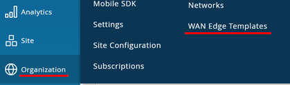
Go to Organization > WAN Edge Templates:
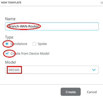
Create a new template with the following parameters:
- Name=
Branch-WAN-Router - Type=
Standalone - Create from Device Model=
Checked - Model=
<Select your Model>
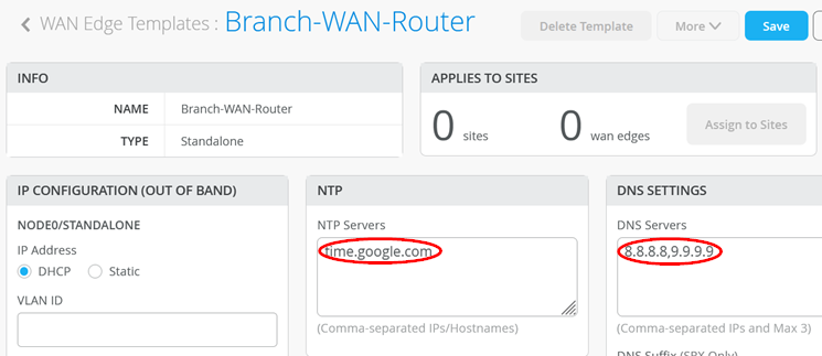
After the template has been created, start with basic configuration settings based on your environment such as the following:
- NTP=
time.google.com - DNS Servers=
8.8.8.8, 9.9.9.9
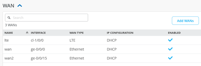
When you check the template, you should see the following preconfigured WAN interfaces. We are going to use the “wan” ge-0/0/0 interface to obtain a DHCP lease from the broadband router.
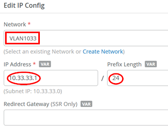
We are going to modify the LAN interfaces of this template. Delete the preconfigured “lan” interface (not shown here). Then, create a first IP configuration:
- Network=
VLAN1033 - IP Address=
10.33.33.1 - IP-Prefix Length=
24
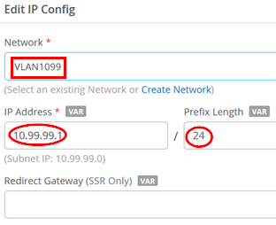
The second IP configuration is:
- Network=
VLAN1099 - IP Address=
10.99.99.1 - IP-Prefix Length=
24
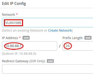
The third IP configuration is:
- Network=
VLAN1088 - IP Address=
10.88.88.1 - IP-Prefix Length=
24
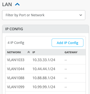
The last IP configuration is:
- Network=
VLAN1044 - IP Address=
10.44.44.1 - IP-Prefix Length=
24
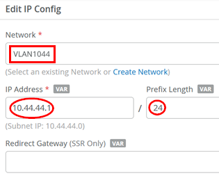
The resulting IP configuration should now look like the figure below:
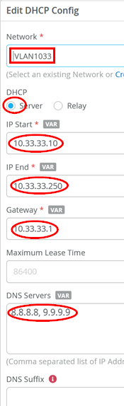
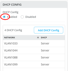
Now, add the first DHCP server configuration:
- Network=
VLAN1033 - DHCP=
Server - IP Start=
10.33.33.10 - IP End=
10.33.33.250 - Gateway=
10.33.33.1 - DNS Servers=
8.8.8.8, 9.9.9.9
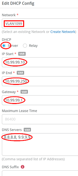
Then, add the second DHCP server configuration:
- Network=
VLAN1099 - DHCP=
Server - IP Start=
10.99.99.10 - IP End=
10.99.99.250 - Gateway=
10.99.99.1 - DNS Servers=
8.8.8.8, 9.9.9.9
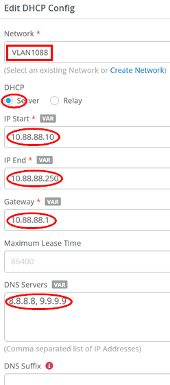
Then add the third DHCP server configuration:
- Network=
VLAN1088 - DHCP=
Server - IP Start=
10.88.88.10 - IP End=
10.88.88.250 - Gateway=
10.88.88.1 - DNS Servers=
8.8.8.8, 9.9.9.9
Then, add the last DHCP server configuration:
- Network=
VLAN1044 - DHCP=
Server - IP Start=
10.44.44.10 - IP End=
10.44.44.250 - Gateway=
10.44.44.1 - DNS Servers=
8.8.8.8, 9.9.9.9
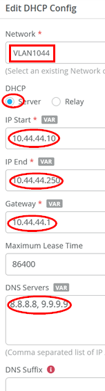
The resulting DHCP server configuration should look like the figure below:
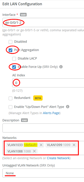
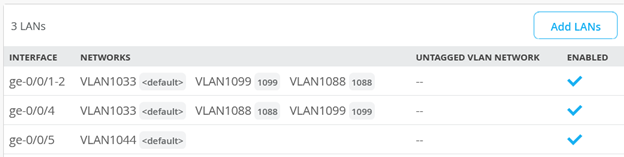
Next, build the LAN interface configurations. The first LAN interface is a LAG with force-up option towards the Virtual Chassis:
- Interface=
ge-0/0/1-2 - Port Aggregation=
Enabled - Enable Force-Up=
Enabled - AE Index=
0 - Networks=
VLAN1033, VLAN1099, VLAN1088 - Untagged VLAN Network=
None(as VLAN1033 is without any tag we do not need to tweak this)
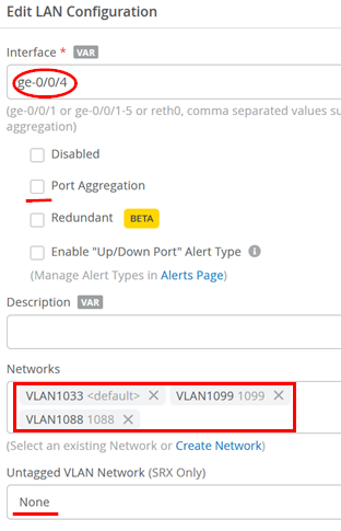
The second LAN interface is a normal trunk port for a single attached switch:
- Interface=
ge-0/0/4 - Port Aggregation=
Unchecked - Networks=
VLAN1033, VLAN1099, VLAN1088 - Untagged VLAN Network=
None(as VLAN1033 is without any tag we do not need to tweak this)
The third LAN interface is an access port with a single VLAN configured to integrate the Juniper Mist Edge into the management network:
- Interface=
ge-0/0/5 - Port Aggregation=
Unchecked - Networks=
VLAN1044 - Untagged VLAN Network=
None(since VLAN1044 is untagged, we do not need to tweak this)
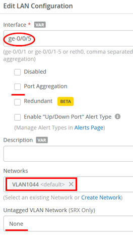
The resulting LAN interface configuration should now look like the figure below:
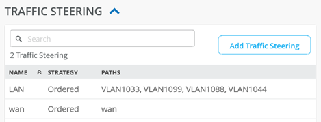
The next step is adding a new destination to the traffic steering policy. This is used to enable communication between the local VLANs, which is required in our example. Add a new traffic steering policy using the following settings:
- Name=
LAN - Strategy=
Ordered - Paths:
- Type=
LAN: VLAN1033 - Type=
LAN: VLAN1099 - Type=
LAN: VLAN1088 - Type=
LAN: VLAN1044
- Type=
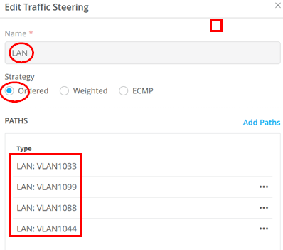
You should now see the following for the traffic steering destinations:
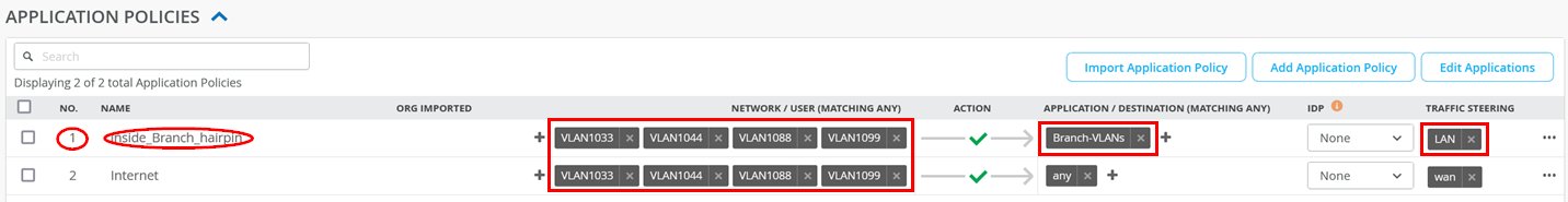
Implement Table 1 for application policies. Parts should already exist that you only need to modify.
| Serial Number | Rule Name | Network | Action | Destination | Steering |
|---|---|---|---|---|---|
| 1 | Inside_Branch_hairpin | VLAN1033, VLAN1044, VLAN1088, VLAN1099 | Pass | Branch-VLANs | LAN |
| 2 | Internet | VLAN1033, VLAN1044, VLAN1088, VLAN1099 | Pass | any | wan |
You should now see the following configuration for application policies after implementing the above table:
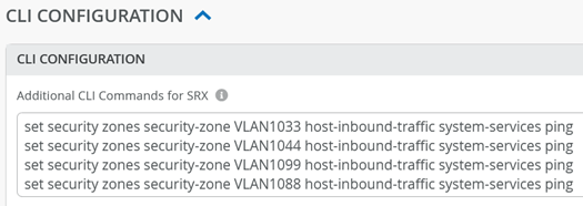
In the current version, clients on the LAN side cannot get an answer when sending ICMP pings to the WAN router as their local gateway. However, receiving pings is crucial for any local debugging. Hence, it is highly recommended that you add some additional Junos OS CLI commands to enable pings for any wired or wireless clients towards the WAN router as the local gateway of the VLAN they are attached to. See the example below:
set security zones security-zone VLAN1033 host-inbound-traffic system-services ping
set security zones security-zone VLAN1044 host-inbound-traffic system-services ping
set security zones security-zone VLAN1099 host-inbound-traffic system-services ping
set security zones security-zone VLAN1088 host-inbound-traffic system-services ping
In the portal, it should look like the figure below:
Click Save to save the template now.
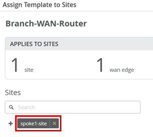
You must assign a site for this template or else it won’t be used on any device.
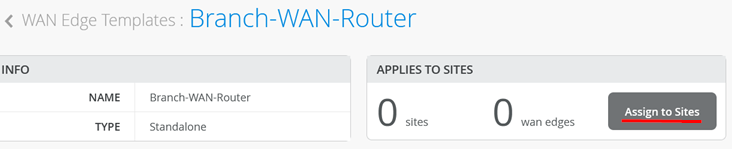
Here, we add the Spoke1 site to the template, which is where our switches are located.
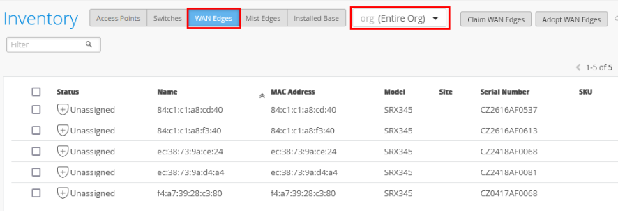
To assign your SRX Series Firewalls to sites, the devices must be present in the Juniper Mist inventory. You can claim or adopt your SRX Series Firewalls to onboard it into the Juniper Mist cloud. After the device is onboarded, the organization inventory shows the device.
To assign an SRX Series Firewall to a site:
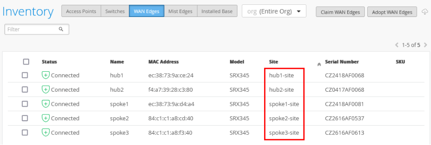
- In the portal, go to Organization > Admin > Inventory.
- Refresh your browser and check under WAN Edges
to find out if your SRX Series Firewall is part of the inventory.
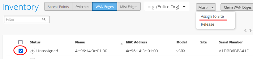
- Assign each SRX Series Firewall to an individual site using the
Assign to Site option:
- On the Assign WAN Edges page, select the site
you want to assign from the list of available sites.
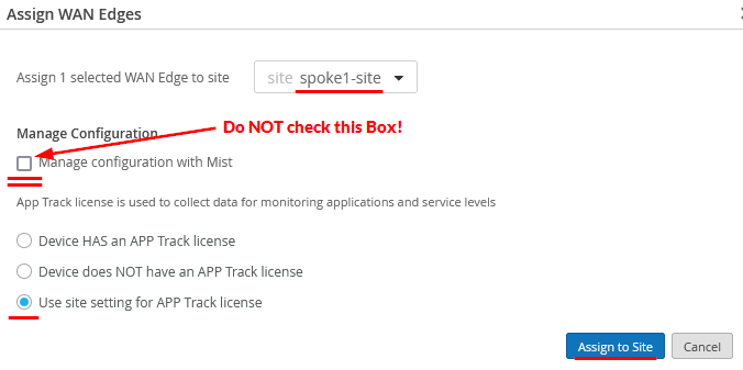
- Do not select the Manage configuration with Mist option. If you do, you may see unwanted changes on your SRX Series Firewall. You can enable the option later if required, after you've assigned the device to the site.
- Select the Use site setting for APP Track
license option if you have a valid Application Security
license, and then click Assign to Site.
The figure below shows changes in the inventory once you assign the device to the site:
- After the device is onboarded, on the WAN
Edges tab, select <your site> and
then click on the device:
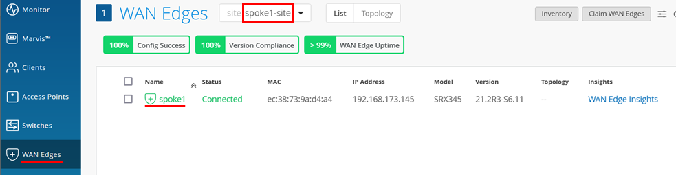
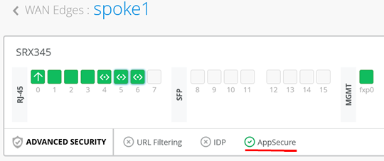
- Check the device and AppSecure status.
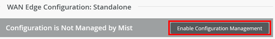
- Now, activate Enable Configuration Management
of the device as the last step so that Juniper Mist can configure
the device.
- (Optional) Use Remote Shell to verify the
device configuration and status after Juniper Mist cloud takes over
management of the device. In our example, you see the output below:
root@spoke1> show interfaces terse
Interface               Admin Link Proto    Local                 Remote
ge-0/0/0                up    up
ge-0/0/0.0              up    up   inet     192.168.173.145/24
.
ge-0/0/1                up    up
ge-0/0/1.0              up    up   aenet    --> ae0.0
ge-0/0/1.1088           up    up   aenet    --> ae0.1088
ge-0/0/1.1099           up    up   aenet    --> ae0.1099
ge-0/0/1.32767          up    up   aenet    --> ae0.32767
ge-0/0/2                up    up
ge-0/0/2.0              up    up   aenet    --> ae0.0
ge-0/0/2.1088           up    up   aenet    --> ae0.1088
ge-0/0/2.1099           up    up   aenet    --> ae0.1099
ge-0/0/2.32767          up    up   aenet    --> ae0.32767
.
ae0                     up    up
ae0.0                   up    up   inet     10.33.33.1/24
ae0.1088                up    up   inet     10.88.88.1/24
ae0.1099                up    up   inet     10.99.99.1/24
ae0.32767               up    up
.
root@spoke1> show lacp interfaces
Aggregated interface: ae0
    LACP state:       Role   Exp   Def  Dist  Col  Syn  Aggr  Timeout  Activity
      ge-0/0/1 FUP    Actor   No    No   Yes  Yes  Yes   Yes     Fast    Active
      ge-0/0/1 FUP  Partner   No   Yes    No   No  Yes   Yes     Fast   Passive
      ge-0/0/2       Actor    No   Yes    No   No   No   Yes     Fast    Active
      ge-0/0/2     Partner    No   Yes    No   No   No   Yes     Fast   Passive
    LACP protocol:        Receive State  Transmit State          Mux State
      ge-0/0/1 FUP              Current   Fast periodic Collecting distributing
      ge-0/0/2                Defaulted   Fast periodic           Detached
The moment you attach the EX Series Switch and power it up, it should obtain a DHCP lease from the WAN router which you can verify as shown below. From time to time, you should also see the phone-home client on the switch trying to contact the redirect server as in our example:
root@spoke1> show dhcp server binding detail
Client IP Address:  10.33.33.11
     Hardware Address:             04:5c:6c:6b:13:42
     State:                        BOUND(LOCAL_SERVER_STATE_BOUND)
     Protocol-Used:                DHCP
     Lease Expires:                2024-03-07 17:02:09 UTC
     Lease Expires in:             85474 seconds
     Lease Start:                  2024-03-06 17:02:09 UTC
     Last Packet Received:         2024-03-06 17:02:09 UTC
     Incoming Client Interface:    ae0.0
     Client Interface Vlan Id:     1
     Server Identifier:            10.33.33.1
     Session Id:                   2
     Client Pool Name:             VLAN1033
root@spoke1> show security flow session source-prefix 10.0.0.0/8
Session ID: 249108247036, Policy name: 01_Internet/20, State: Stand-alone, Timeout: 854, Valid
  In: 10.33.33.11/59874 --> 44.231.144.179/443;tcp, Conn Tag: 0x0, If: ae0.0, Pkts: 8, Bytes: 1278,
  Out: 44.231.144.179/443 --> 192.168.173.145/8983;tcp, Conn Tag: 0x0, If: ge-0/0/0.0, Pkts: 18, Bytes: 13734,
Total sessions: 1
Switch Installation and Configuration
When installing and configuring the Virtual Chassis and standalone switch for the wired part of this lab, we are following the best practice methods shared in more detail in the JVD for Distributed Branch EX Series. In our case, we connect the standalone switch through one trunk port to the WAN router while the Virtual Chassis, for redundancy reasons, utilizes a LAG with force-up configuration on the WAN router (see Figure 2). The switch and all attached APs then get a DHCP lease through the native VLAN1033 from the WAN router and are then able to start communicating with the Juniper Mist cloud to be managed. Figure 3 shows the intended setup for this lab (without the APs).
The following list of steps summarizes the process used to configure the switches in this chapter and is immediately followed by a detailed description of those steps:
- Define a switch template
- Connect the uplinks to the WAN router
- Claim and ZTP to the Juniper Mist cloud
- Assign the switch to a site
- Optional: Upgrade firmware
- Perform Virtual Chassis formation
- Onboard standalone switches
- Configure access ports for wired clients and APs
- Test the configuration
Define a Switch Template
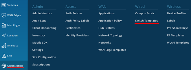
We start by navigating to Organization > Switch Templates:
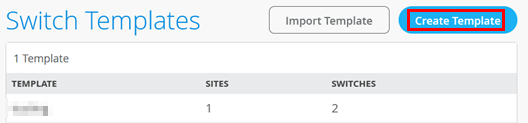
Then, use Create Template or import a JSON file from an existing template:
Using a JSON file, you can import the following configuration to avoid the manual steps described below:
{
"ntp_servers": [],
"dns_servers": [
"8.8.8.8",
"9.9.9.9"
],
"dns_suffix": [],
"additional_config_cmds": [],
"networks": {
"vlan1088": {
"vlan_id": "1088",
"subnet": ""
},
"vlan1099": {
"vlan_id": "1099",
"subnet": ""
}
},
"port_usages": {
"dynamic": {
"mode": "dynamic",
"rules": []
},
"vlan1099-noauth": {
"mode": "access",
"disabled": false,
"port_network": "vlan1099",
"voip_network": null,
"stp_edge": true,
"all_networks": false,
"networks": null,
"port_auth": null,
"speed": "auto",
"duplex": "auto",
"mac_limit": 0,
"persist_mac": false,
"poe_disabled": false,
"enable_qos": false,
"storm_control": {},
"mtu": null,
"description": "",
"disable_autoneg": false,
"mac_auth_protocol": null,
"enable_mac_auth": null,
"mac_auth_only": null,
"guest_network": null,
"bypass_auth_when_server_down": null,
"stp_p2p": false,
"stp_no_root_port": false,
"allow_multiple_supplicants": null,
"dynamic_vlan_networks": null,
"reauth_interval": null
},
"vlan1099-mab": {
"disabled": false,
"mode": "access",
"port_network": "vlan1099",
"voip_network": null,
"stp_edge": true,
"mac_auth_protocol": "pap",
"all_networks": false,
"networks": null,
"port_auth": "dot1x",
"allow_multiple_supplicants": true,
"enable_mac_auth": true,
"mac_auth_only": true,
"guest_network": null,
"bypass_auth_when_server_down": false,
"dynamic_vlan_networks": null,
"speed": "auto",
"duplex": "auto",
"mac_limit": 0,
"persist_mac": false,
"poe_disabled": false,
"enable_qos": false,
"storm_control": {},
"mtu": null,
"description": "",
"disable_autoneg": false
},
"vlan1099-eap": {
"disabled": false,
"mode": "access",
"port_network": "vlan1099",
"voip_network": null,
"stp_edge": true,
"mac_auth_protocol": null,
"all_networks": false,
"networks": null,
"port_auth": "dot1x",
"allow_multiple_supplicants": false,
"enable_mac_auth": false,
"mac_auth_only": false,
"guest_network": null,
"bypass_auth_when_server_down": false,
"dynamic_vlan_networks": null,
"speed": "auto",
"duplex": "auto",
"mac_limit": 0,
"persist_mac": false,
"poe_disabled": false,
"enable_qos": false,
"storm_control": {},
"mtu": null,
"description": "",
"disable_autoneg": false
}
},
"switch_matching": {
"enable": true,
"rules": []
},
"switch_mgmt": {
"config_revert_timer": 10,
"root_password": "juniper123",
"protect_re": {
"enabled": false
},
"tacacs": {
"enabled": false
}
},
"radius_config": {
"auth_servers": [
{
"port": "1812",
"host": "10.44.44.5",
"secret": "juniper123"
}
],
"acct_servers": [],
"auth_servers_timeout": 5,
"auth_servers_retries": 3,
"fast_dot1x_timers": false,
"acct_interim_interval": 0,
"auth_server_selection": "ordered",
"coa_enabled": false,
"coa_port": ""
},
"vrf_config": {
"enabled": false
},
"remote_syslog": {
"enabled": false
},
"snmp_config": {
"enabled": false
},
"dhcp_snooping": {
"enabled": false
},
"acl_policies": [],
"mist_nac": {
"enabled": true,
"network": null
},
"port_mirroring": {},
"disabled_system_defined_port_usages": [],
"bgp_config": null,
"routing_policies": {},
"name": "naclab"
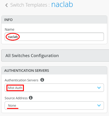
}After creating the template, the first and most important step is configuring the switch to use the RadSec tunnel towards the Juniper Mist authentication cloud. Here, you configure the following settings:
- Authentication Servers=
Mist Auth - Source Address=
None(this is the default, and we do not need to change it)
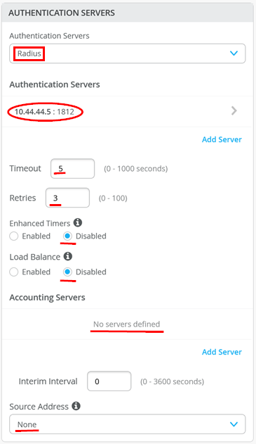
When testing emulated third-party products using a Juniper Mist Edge device as proxy, we make the following changes:
- Authentication Servers=
Mist Auth - Auth Server1
- Hostname / IP Address=
10.44.44.5 - Port=
1812 - Shared Secret=
juniper123(or whatever is configured to be used between the two)
- Hostname / IP Address=
- Timeout=
5(the default) - Retires=
3(the default) - Enhanced Timers=
Disabled(the default) - Load Balance=
Disabled(the default) - Accounting Servers=
None(The Juniper Mist Edge does not listen on accounting port 1813) - Source Address=
None(this is the default, and we do not need to change it)
Next, define port profiles for uplinks, APs, and authenticating wired clients.
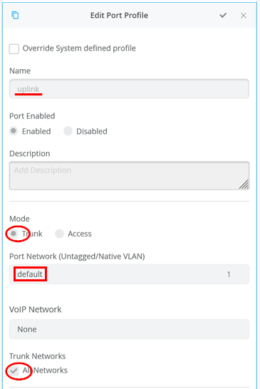
Let’s first review two default port profiles we intend to use. The first one is the “uplink” profile where the important settings are:
- Name=
uplink - Port Enabled=
Enabled - Mode=
Trunk - Port Network (Untagged/Native VLAN)=
default(VLAN-ID=1) (Remember that the WAN router has VLAN1033 configured as the native VLAN. Hence, this enables us to get DHCP leases for the range 10.33.33.0/24 from the WAN router as both the switch and WAN router remove the VLAN tag) - Trunk Networks=
All Networks(Allows you to add more VLANs later without needing to change this link)
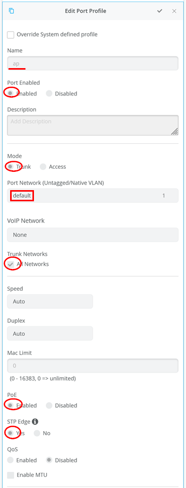
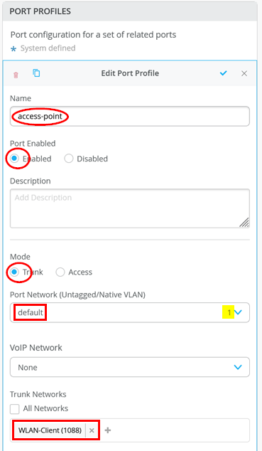
The next default port profile is used for APs:
- Name=
ap - Port Enabled=
Enabled - Mode=
Trunk - Port Network (Untagged/Native VLAN)=
default(VLAN-ID=1) (Here, we are stitching the native uplink VLAN from WAN router further to the AP to manage the AP) - Trunk Networks=
All Networks - PoE=
Enabled - STP Edge=
Yes
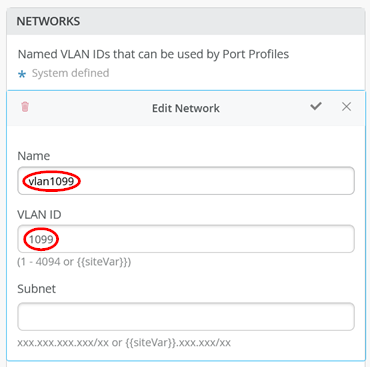
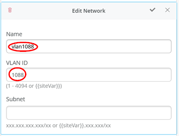
Before we can continue, we need to define the three VLANs we use in the switching and AP environment. VLAN1033 does not need to be defined as we continue using the existing default VLAN1. The first network is the one for wired clients. So, we configure:
- Name=
vlan1099 - VLAN-ID=
1099 - Subnet=
Empty(Enter “10.99.99.0/24” here when using a campus fabric).
The second network is the transport for wireless clients. So, we configure:
- Name=
vlan1088 - VLAN-ID=
1088 - Subnet=
Empty(Enter “10.88.88.0/24” here when using a campus fabric).
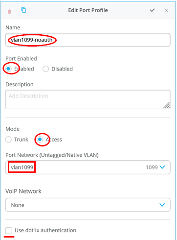
Next, we configure for wireless clients using VLAN1099 three different port profiles for testing. We start with one that has no authentication at all so we can use it for client connectivity testing without Access Assurance.
- Name=
vlan1099-noauth - Port Enabled=
Enabled - Mode=
Access - Port Network (Untagged/Native VLAN)=
vlan1099 - Use dot1x authentication=
Unchecked
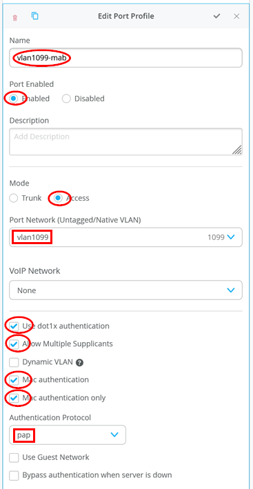
The next port profile is used if the attached client does not support EAP, so we have to fall back to MAC address-based authentication only.
- Name=
vlan1099-mab - Port Enabled=
Enabled - Mode=
Access - Port Network (Untagged/Native VLAN)=
vlan1099 - Use dot1x authentication=
Checked - Allow Multiple Supplicants=
Checked(This recommended setting is better enabled for labs as sometimes multiple MAC addresses appear on a port, and you do not want unknown MAC addresses to block further authentication on the port). - Dynamic VLAN=
Unchecked - Mac Authentication=
Checked(Enables MAB) - Mac Authentication only=
Checked(Disables all EAP authentication for this port, otherwise you must wait 60 seconds) - Authentication Protocol=
pap(This is a best practice setting. This has no effect if the switch uses a RadSec tunnel. This setting defines the used MAB RADIUS authentication for third-party RADIUS servers or Mist-Edge as RadSec-Proxy) - Use Guest Network=
Unchecked - Bypass authentication when server is
down=
Unchecked
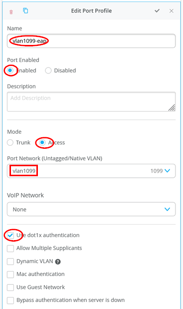
Finally, the last port profile is used for EAP supplicants, which should be the best practice for all clients we have in the environment:
- Name=
vlan1099-eap - Port Enabled=
Enabled - Mode=
Access - Port Network (Untagged/Native VLAN)=
vlan1099 - Use dot1x authentication=
Checked - Allow Multiple Supplicants=
Unchecked - Dynamic VLAN=
Unchecked - Mac Authentication=
Unchecked - Mac Authentication only=
Unchecked - Use Guest Network=
Unchecked - Bypass authentication when server is
down=
Unchecked
Do not forget to save your template.

After saving the template, assign it to a site where you intend to use it.

Here, we add “site1” to our template before we apply it.
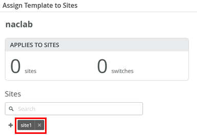
Resulting in the below example:
Connect the Uplinks to the WAN Router
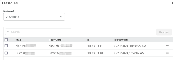
In this step, use the revenue ports on the switches and connect them to the WAN router. Power on the switches afterward. After about 5 minutes, they are booted up and should request DHCP leases.
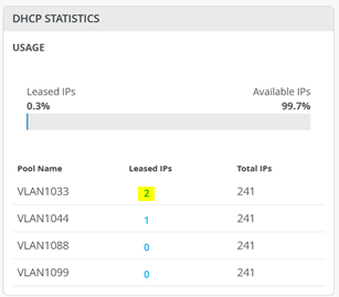
You can review the DHCP lease list to see more information:
Claim and ZTP to Juniper Mist Cloud
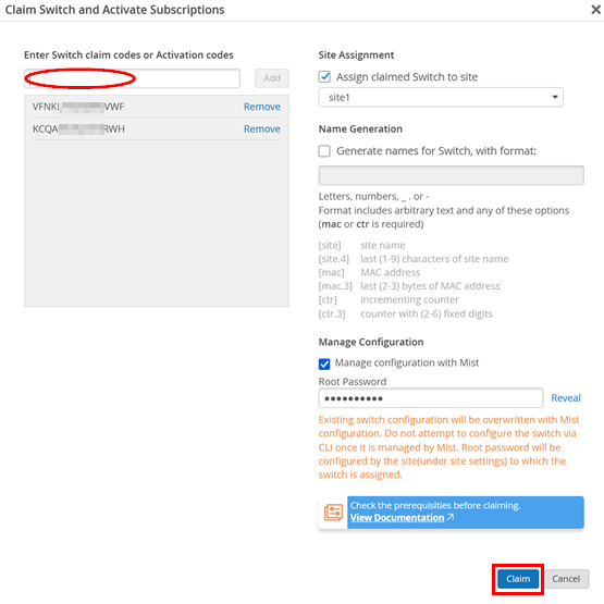
There are multiple methods of onboarding a switch to the Juniper Mist cloud. They are all described in the Distributed Branch EX Series JVD. To simplify things for this lab, we use the claim and ZTP method. The process of ZTP is described here for review. The process in our case is described by the following:
- Locate the QR label on the device and scan or read the claim code.
- Go to Organization > Inventory.
- Select Switches and then click on Claim Switches, similar to what you see in Figure 6:
Assign to Site
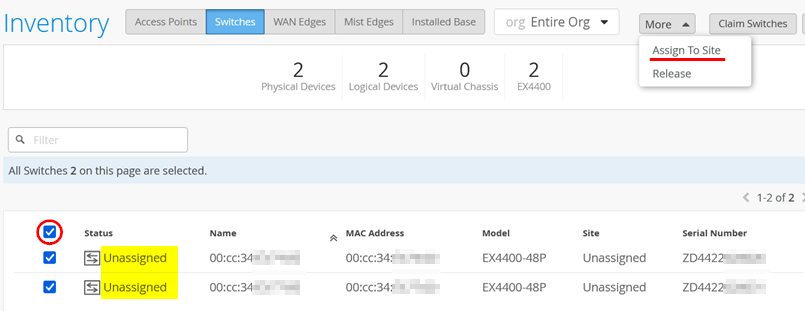
If you have not already assigned the switches to a site as shown in Figure 6, remember that you must first assign switches to a site before you can manage them. As seen in Figure 7, select the switches and then from the More menu, select Assign To Site.
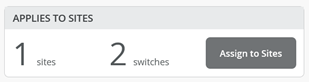
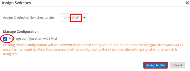
Select the site where these switches will be used and enable Manage configuration with Mist before you click on Assign to Site.
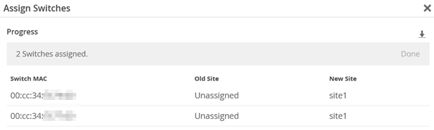
Something like the figure below should be displayed:
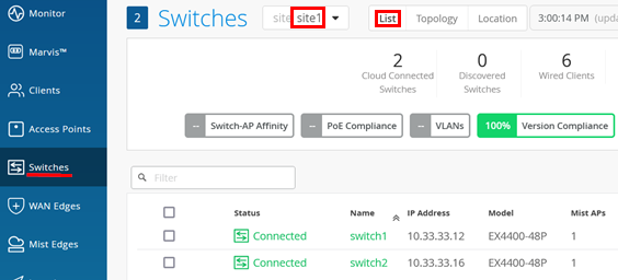
After the switches receive their DHCP lease from the WAN router and get redirected to the correct Juniper Mist cloud, we should see them appearing in the “Connected” state after navigating to Switches > select <site> > List.
Optional: Upgrade Firmware
When planning to form a Virtual Chassis, it is recommended that all switch members have the same Junos OS firmware version running. Follow the upgrade procedure if that is not the case.
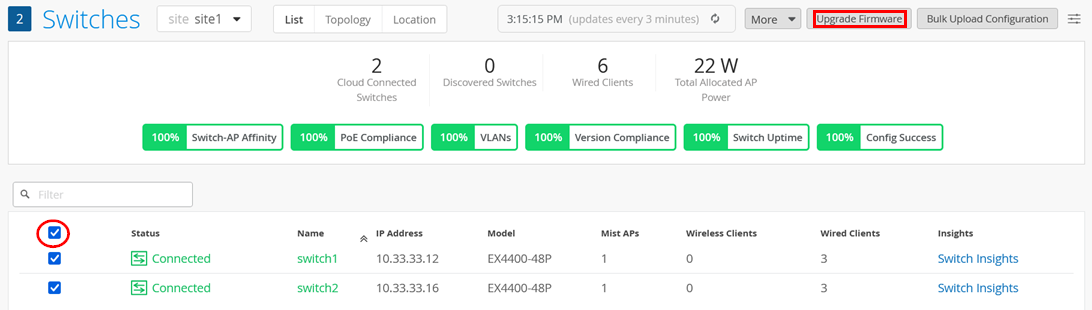
It is suggested that you upgrade the Junos firmware to the suggested version before you put the switch into production. To achieve this, select the switches then select Upgrade Firmware as shown in the figure below:
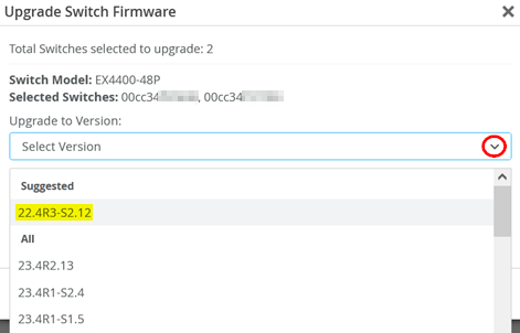
This will open a dialogue where you can select the Junos OS firmware under Suggested for your switch model as shown in the figure below:
Further information about this process is given in the JVD for Distributed Branch EX Series in this chapter.
Perform a Virtual Chassis Formation
If you plan to build a Virtual Chassis, you can find the instructions for how to do so for each switch model in the JVD for Distributed Branch EX Series. The following links are for the most common switch models:
- Switches that support ZTP: Workflow for VC formation with Mist for EX3400, EX4100, EX4100-F, EX4300, EX4400 & EX4600
- Switches that need to be pre-staged for Virtual Chassis formation: Workflow for Virtual Chassis Formation with Mist for EX2300, EX4650 and QFX5120
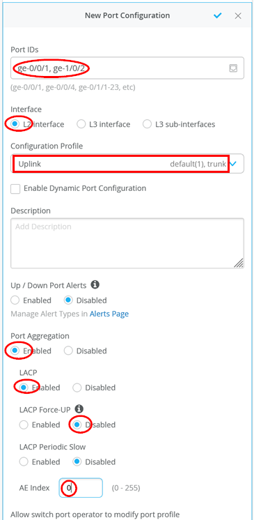
After the Virtual Chassis has been formed, configure the LAG uplink. In our case, configure the following:
- Port IDs=
ge-0/0/1, ge-1/0/2 - Interface=
L2 Interface - Configuration Profile=
Uplink - Port Aggregation=
Enabled - LACP=
Enabled - LACP Force-UP=
Disabled(This option is only needed for downlink interfaces such as those on the WAN router) - AE Index=
0
(Optional) You can Remote Shell to the switch to see the LAG and LACP states like in this example output:
root@switch1> show lacp interfaces
Aggregated interface: ae0
    LACP state:           Role   Exp   Def  Dist  Col  Syn  Aggr  Timeout  Activity
      ge-0/0/1           Actor    No    No   Yes  Yes  Yes   Yes     Fast    Active
      ge-0/0/1         Partner    No    No   Yes  Yes  Yes   Yes     Fast    Active
      ge-1/0/2           Actor    No    No   Yes  Yes  Yes   Yes     Fast    Active
      ge-1/0/2         Partner    No    No   Yes  Yes  Yes   Yes     Fast    Active
    LACP protocol:        Receive State  Transmit State          Mux State
      ge-0/0/1                  Current   Fast periodic Collecting distributing
      ge-1/0/2                  Current   Fast periodic Collecting distributing
Onboard Standalone Switches
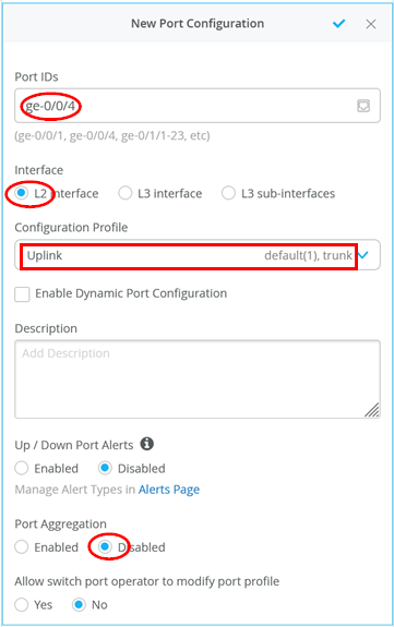
Onboarding the standalone switches involves using the previously demonstrated steps for bringing the switch online and managing it in Juniper Mist cloud. Once this is done, merely configure the uplink interface towards the WAN router with the Uplink profile since multiple VLANs must be supported on this link. In our example, the configuration is:
- Port IDs=
ge-0/0/4 - Interface=
L2 Interface - Configuration Profile=
Uplink - Port Aggregation=
Disabled
(Optional) You may want to use Remote Shell to determine the VLANs configured on port ge-0/0/4.
root@switch2> show vlans
Routing instance        VLAN name             Tag          Interfaces
default-switch          default               1
.
.
                                                           ge-0/0/4.0*
.
.
default-switch          vlan1088              1088
                                                           ge-0/0/4.0*
default-switch          vlan1099              1099
                                                           ge-0/0/4.0*
Configure Access Ports for Wired Clients and APs
Next, configure the access ports for the wired clients and APs. We suggest doing that by using switch templates to synchronize configurations better. For our lab however, individually assigned profiles make more sense since we are more flexible with changing them.
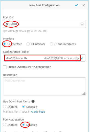
For the wired client using VLAN 1099, we start with the “vlan1099-noauth” profile like that shown below:
- Port IDs=
ge-0/0/0 - Interface=
L2 Interface - Configuration Profile=
vlan1099-noauth - Port Aggregation=
Disabled
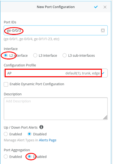
For the AP, we leverage the built-in AP profile:
- Port IDs=
ge-0/0/3 - Interface=
L2 Interface - Configuration Profile=
AP - Port Aggregation=
Disabled
Test Configuration
Next, check whether the wired clients are connected to the infrastructure and can see each other without any authentication performed yet. Choose whatever method is available in your lab to connect to a wired client attached to your switches. Below, see commands executed on a Linux client testing the connectivity in the network, for example:
# review the local interfaces
root@desktop1:~# ip a
1: lo: <LOOPBACK,UP,LOWER_UP> mtu 65536 qdisc noqueue state UNKNOWN group default qlen 1000
    link/loopback 00:00:00:00:00:00 brd 00:00:00:00:00:00
    inet 127.0.0.1/8 scope host lo
       valid_lft forever preferred_lft forever
    inet6 ::1/128 scope host
       valid_lft forever preferred_lft forever
1: ens5: <BROADCAST,MULTICAST,UP,LOWER_UP> mtu 1500 qdisc fq_codel state UP group default qlen 1000
    link/ether 52:54:00:7a:8a:50 brd ff:ff:ff:ff:ff:ff
    inet 10.99.99.99/24 brd 10.99.99.255 scope global ens5
       valid_lft forever preferred_lft forever
    inet6 fe80::5054:ff:fe7a:8a50/64 scope link
       valid_lft forever preferred_lft forever
# review the routes
root@desktop1:~# ip r
default via 10.99.99.1 dev ens5 proto static
10.99.99.0/24 dev ens5 proto kernel scope link src 10.99.99.99
# test the connection via WAN-Router to internet
root@desktop1:~# ping -c3 8.8.8.8
PING 8.8.8.8 (8.8.8.8) 56(84) bytes of data.
64 bytes from 8.8.8.8: icmp_seq=1 ttl=53 time=3.65 ms
64 bytes from 8.8.8.8: icmp_seq=2 ttl=53 time=3.54 ms
64 bytes from 8.8.8.8: icmp_seq=3 ttl=53 time=3.63 ms
.
# ping the wireless client on the same VLAN in the next Switch
root@desktop1:~# ping -c3 10.99.99.42
PING 10.99.99.42 (10.99.99.42) 56(84) bytes of data.
64 bytes from 10.99.99.42: icmp_seq=1 ttl=64 time=1.47 ms
64 bytes from 10.99.99.42: icmp_seq=2 ttl=64 time=0.676 ms
64 bytes from 10.99.99.42: icmp_seq=3 ttl=64 time=0.679 ms
.
# check the ARP-resolution
root@desktop1:~# ip n
10.99.99.42 dev ens5 lladdr 52:54:00:bd:8c:e8 STALE
10.99.99.1 dev ens5 lladdr 4c:96:14:55:7f:80 STALE
# test the DHCP-Server on WAN-Router
root@desktop1:~# dhclient -v ens5
Internet Systems Consortium DHCP Client 4.4.1
Copyright 2004-2018 Internet Systems Consortium.
All rights reserved.
For info, please visit https://www.isc.org/software/dhcp/
Listening on LPF/ens5/52:54:00:7a:8a:50
Sending on   LPF/ens5/52:54:00:7a:8a:50
Sending on   Socket/fallback
DHCPDISCOVER on ens5 to 255.255.255.255 port 67 interval 3 (xid=0xf4b2324f)
DHCPOFFER of 10.99.99.10 from 10.99.99.1
DHCPREQUEST for 10.99.99.10 on ens5 to 255.255.255.255 port 67 (xid=0x4f32b2f4)
DHCPACK of 10.99.99.10 from 10.99.99.1 (xid=0xf4b2324f)
bound to 10.99.99.10 -- renewal in 35575 seconds.
# test the DNS resolution
root@desktop1:~# host www.google.com
www.google.com has address 172.217.164.100
www.google.com has IPv6 address 2607:f8b0:4005:80b::2004
Access Point Installation and Configuration
Pre-conditions That Must be Met for AP Onboarding
To be able to execute this lab, we assume that the following conditions are met:
- The AP is cabled to the EX Series Switch and has power (through an external power supply or through PoE).
- If PoE is used, the switch must have enough PoE power available and must support, at a minimum, IEEE 802.3af or IEEE 802.3at depending on your AP model.
- Link Layer Discovery Protocol (LLDP) should be activated (this is not mandatory) on switches and routers for debugging.
- It is necessary to have completely followed the instructions
from the above chapters as those include instructions for the
following:
- A DHCP server is configured for the AP management VLAN 1033 subnet 10.33.33.0/24 in this branch. In our example, that is done on the WAN router.
- An additional VLAN 1088 subnet 10.88.88.0/24 is used for WLAN clients.
- An additional VLAN 1099 subnet 10.99.99.0/24 is used for wired clients.
- On the WAN router, a LAG is formed to the switch containing native VLAN 1033 and VLANs 1088 and 1099 as trunk. Keep in mind that without further changes, the native VLAN from the uplink gets assigned to VLAN 1 on the switch where irb.0 for in-band management is assigned. Providing that management VLAN to a downstream device such as an AP needs to reference this VLAN 1.
- On the port where the switch is attached, the default VLAN 1 is native and VLAN 1088 is trunked. We did not add VLAN 1099 for wired clients again as the port does not need to support it.
- The WAN router must implement some form of source NAT on the WAN interfaces to allow management traffic towards the Juniper Mist cloud.
Below is just a reminder about the minimal configuration on the switch (apart from the uplink):
How to Claim APs to an Organization?
APs can be claimed to any organization by using either an activation code, claim code, or QR code.
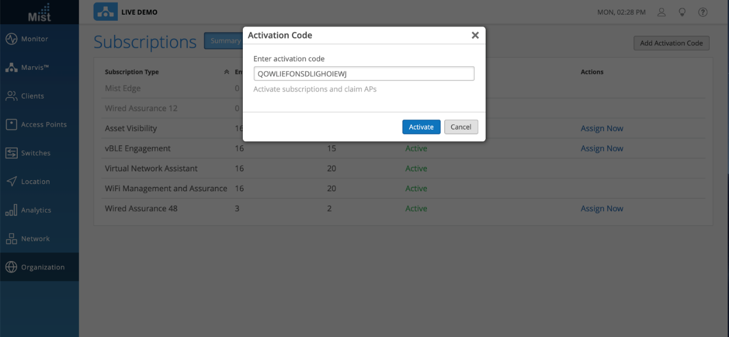
Example: Activation Code
Whenever you order APs, our sales operations team will send you an activation code which can be used for claiming the APs and subscriptions as per the purchase order. You can use this activation code to claim APs in one go. To claim the APs, go to the Organization > Subscriptions page and select Add Activation Code in the upper-right corner. Once the activation code is added and activated, all the APs will automatically get claimed to the organization. You can see the list of APs on the Inventory page (Organization > Inventory).
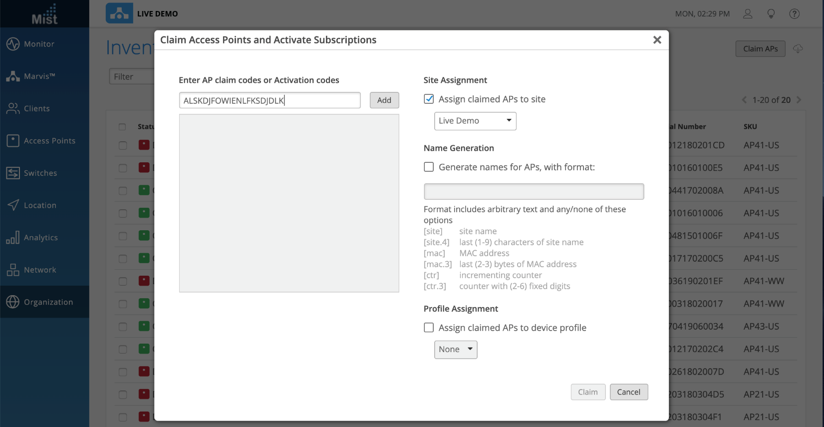
Example: AP Claim Code
You can claim individual APs to your organization by navigating to Organization > Inventory > Claim APs and entering in the claim code found on the back of each AP.
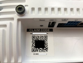
Example: AP QR Code
Using the Mist™ AI mobile app, you can scan the QR code printed on the back of Juniper APs to claim APs to your organization. Our app is compatible with both iOS and Android devices. Read more about it here.
Where Can I Get the Claim Codes for the APs in My Organization?
The claim code of the AP is written on the back of the AP where the QR code of the AP is printed.
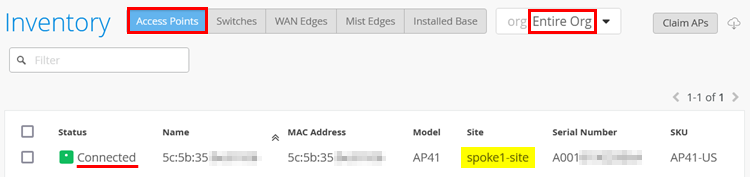
Troubleshoot: Bringing the AP Online as “Connected” into the Inventory
We assume in this step you have used any of the methods above to claim the AP into the inventory. When you refresh the browser window after 3-5 minutes, the AP should appear automatically in the “Connected” state in the inventory such as seen in Figure 9:
If that is the case, you can skip this section since it describes how to troubleshoot if the AP does not appear as “Connected”.
The troubleshooting of Juniper APs is explained in detail here. This remaining section will focus on what to troubleshoot on the EX Series Switch side to help bring the AP into the “Connected” state in the inventory.
If the AP is not assigned to a site, it will always appear in the “Disconnected” state irrespective of its connectivity to the cloud. Remember that along with claiming the AP, assigning the AP to a site is mandatory.
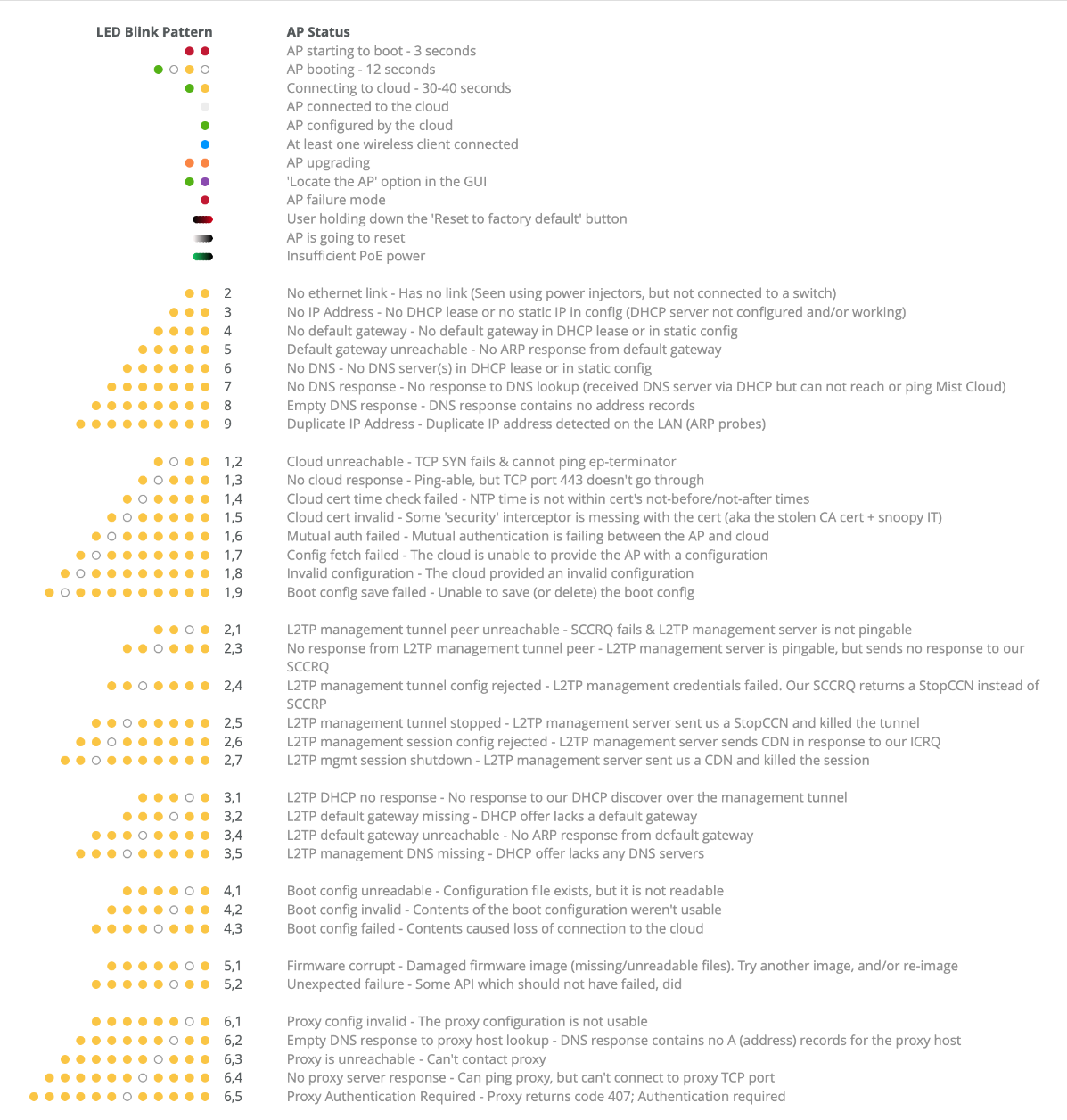
If you are local to the site, check the AP’s status LED since its blinking code may indicate the error by cross referencing it with Figure 10.
The first thing to do is to understand the source of the error by viewing the AP’s status LED. If you can’t see the LED on the AP, reboot it. If the AP is powered by PoE, then you can reboot it by using one of the two following methods:
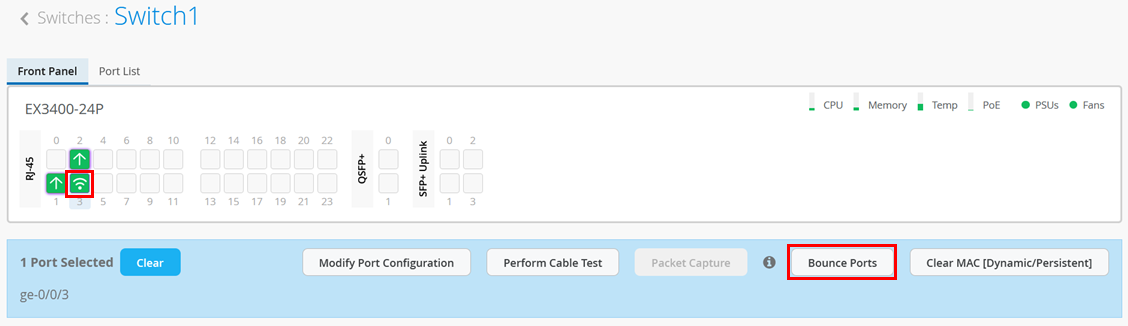
- Use the switch’s Bounce Ports option found on the portal. Selecting the port where the AP is attached opens a pane where you can choose to bounce a particular port which will also power cycle the attached AP.
You will see a new window with information about the bounce port status as shown in Figure 11:
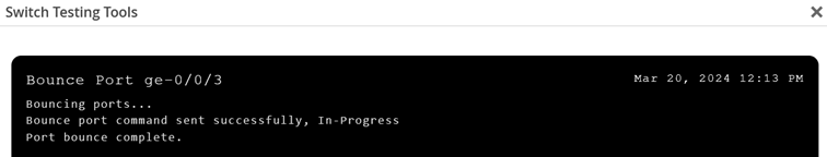
Bouncing a port may take several minutes since two Junos OS configuration commits must happen as part of the process.
- Change the PoE interface configuration using Remote
Shell (This option is not recommended).
cli
edit
set poe interface ge-0/0/3 disable
commit
# wait >20seconds
delete poe interface ge-0/0/3 disable
commit and-quit
exit
If the AP is powered by an external power supply, you must unplug it for a while and then power it on again. The AP has no console connection like the switches.
The next step is to use Remote Shell to the switch to review items such as:
- Is the port that the AP is connected to showing as “up”?
- Is the port that the AP is connected to correctly configured and forwarding packets?
- Does the MAC address of the AP appear on the expected port?
- Do you see the AP appearing as an LLDP neighbor?
- Assuming the AP is powered by PoE, what’s the actual power draw?
The following example output shows an AP that is attached to interface ge-0/0/3:
- Check if the port is administratively “up” and a
physical link detected.
root@Switch1> show interfaces terse
Interface               Admin Link Proto    Local                 Remote
ge-0/0/0                up    down
ge-0/0/0.0              up    down eth-switch
ge-0/0/1                up    up
ge-0/0/1.0              up    up   aenet    --> ae0.0
ge-0/0/2                up    up
ge-0/0/2.0              up    up   aenet    --> ae0.0
ge-0/0/3                up    up
ge-0/0/3.0              up    up   eth-switch
ge-0/0/4                up    down
ge-0/0/4.0              up    down eth-switch
.
- Then, check that the port is in forwarding mode and that it is
configured with the expected VLAN (the default VLAN in this
example) and is in access mode. Also, verify that the VLAN assigned
is the same VLAN that the WAN router uses for DHCP lease handouts
for AP management.
root@Switch1> show ethernet-switching interface ge-0/0/3 Routing Instance Name : default-switch Logical Interface flags (DL - disable learning, AD - packet action drop, LH - MAC limit hit, DN - interface down, MMAS - Mac-move action shutdown, AS - Autostate-exclude enabled, SCTL - shutdown by Storm-control, MI - MAC+IP limit hit) Logical Vlan TAG MAC MAC+IP STP Logical Tagging interface members limit limit state interface flags ge-0/0/3.0 32768 0 tagged WLAN-Client 1088 32768 0 Forwarding tagged default 1 32768 0 Forwarding untagged - Next, check if the MAC address (also printed on the QR code) of
the AP appears on the switch’s interface as expected.
root@Switch1> show ethernet-switching table
MAC flags (S - static MAC, D - dynamic MAC, L - locally learned, P - Persistent static, C - Control MAC
           SE - statistics enabled, NM - non configured MAC, R - remote PE MAC, O - ovsdb MAC)
Ethernet switching table : 2 entries, 2 learned
Routing instance : default-switch
    Vlan                MAC                 MAC         Age    Logical                NH        RTR
    name                address             flags              interface              Index     ID
    default             5c:5b:35:be:81:06   D             -   ge-0/0/3.0             0         0
    default             ee:38:73:9a:d4:a5   D             -   ae0.0                  0         0
At this point, it is appropriate to check the port authorization status of the AP as well. Sometimes it is intended that the AP authorizes itself to the switch it is attached to and sometimes this is not required, and someone accidentally applies a port profile with authentication enabled.
- Next, check if you see the AP’s MAC address appearing as
an LLDP neighbor’s chassis ID. The port info may be different
based on the AP model you have; however, the system name may help
you determine more about the state of the AP:
- When no LLDP system name is reported, the AP has a connection issue. For example, it cannot receive a DHCP lease.
- When the LLDP system name is “Mist”, like in the example below, then the AP is usually up but not assigned to an inventory.
- When the LLDP system name is the MAC address of the AP or the inventory name, then it should already be in the “Connected” state in the inventory of your organization and you can start applying more configuration.
root@Switch1> show lldp neighbors Local Interface Parent Interface Chassis Id Port info System Name ge-0/0/1 ae0 ec:38:73:9a:d5:24 ge-0/0/5 spoke1 ge-0/0/2 ae0 ec:38:73:9a:d5:24 ge-0/0/6 spoke1 ge-0/0/3 - 5c:5b:35:be:81:06 ETH0 Mist - Should you have PoE running on the switch, you should also
check the power consumption of the AP. The PoE mode negotiated
depends on the AP model (usually 802.3af or 802.3at) and can be
verified in the datasheet. Depending on the configuration state and
radio usage, you should see differences in the actual “power
consumed” report.
root@Switch1> show poe interface
.
.
root@Switch1> show poe interface ge-0/0/3
PoE interface status:
PoE interface                :  ge-0/0/3
Administrative status        : Enabled
Operational status           :   ON
Power limit on the interface : 19.5W (L)
Priority                     : High
Power consumed               : 7.3W
Class of power device        :        4
PoE Mode                     :   802.3at
  (L) LLDP-negotiated value on the port.
- The following checks should be done on the WAN router. In our
example, we use a Remote Shell to an SRX Series Firewall acting as
a WAN router. You should look for the DHCP lease requests from the
AP and verify that you see two sessions using port 443 for TCP/UDP
towards the Juniper Mist cloud as shown in the example below:
root@spoke1> show dhcp server binding
IP address        Session Id  Hardware address   Expires     State      Interface
10.33.33.12       3           04:5c:6c:6b:13:42  54553       BOUND      ae0.0
10.33.33.15       6           5c:5b:35:be:81:06  48923       BOUND      ae0.0
root@spoke1> show arp interface ae0.0
MAC Address       Address         Name                      Interface               Flags
04:5c:6c:6b:13:42 10.33.33.12     10.33.33.12               ae0.0                   permanent
5c:5b:35:be:81:06 10.33.33.15     10.33.33.15               ae0.0                   permanent
Total entries: 2
root@spoke1> show security flow session source-prefix 10.33.33.15
Session ID: 34359960425, Policy name: 01_Internet/20, State: Stand-alone, Timeout: 60, Valid
  In: 10.33.33.15/40267 --> 44.204.233.81/443;udp, Conn Tag: 0x0, If: ae0.0, Pkts: 45026, Bytes: 8408428,
  Out: 44.204.233.81/443 --> 192.168.173.145/23463;udp, Conn Tag: 0x0, If: ge-0/0/0.0, Pkts: 5524, Bytes: 407857,
Session ID: 34359962715, Policy name: 01_Internet/20, State: Stand-alone, Timeout: 1794, Valid
  In: 10.33.33.15/37165 --> 54.144.163.241/443;tcp, Conn Tag: 0x0, If: ae0.0, Pkts: 8997, Bytes: 4866046,
  Out: 54.144.163.241/443 --> 192.168.173.145/28185;tcp, Conn Tag: 0x0, If: ge-0/0/0.0, Pkts: 5063, Bytes: 421001,
Total sessions: 2
In rare cases, especially with loaned or lab equipment, someone has already claimed the AP in another organization or cloud and forgotten to release it from inventory. Naturally, this will preclude any usage in another organization. Open a support ticket if that is the case.
Mist Edge Proxy Installation and Configuration
When deploying Juniper Mist Edge as proxy for RadSec towards the Juniper Mist authentication cloud, the suggested workflow is described in the following steps:
- Deploy the Juniper Mist Edge appliance at the central location where a legacy RADIUS server is usually located. In our simple JVD test lab, it is attached to the WAN router as an exception. In a production environment, the location is usually the corporate headquarters, making the system reachable through the corporate VPN by any branch sites.
- If you only intend to use the Juniper Mist Edge as RADIUS
proxy, then you only need to connect the out-of-band management
(OOBM) interface. It’s used for:
- Allowing the Juniper Mist Edge to contact the Juniper Mist cloud to get managed.
- Create the RadSec proxy instance that listens on the RADIUS ports and then tunnels the messages through RadSec towards the Juniper Mist authentication cloud.
- OPTIONAL: Connect the Juniper Mist Edge device’s other Interfaces if it is also used for tunnel termination for APs.
- Initially, the OOBM port asks for a DHCP lease, and you must provide one through your infrastructure.
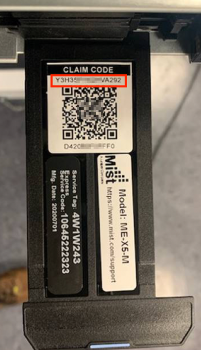
- Get the claim code or QR code by extending the pull-out tag located on the front of the appliance in the lower-right corner. This allows for ZTP.
- Create the device in the Juniper Mist cloud via the claim code.
- Wait for the Juniper Mist Edge device to appear as “Connected” and “Registered”.
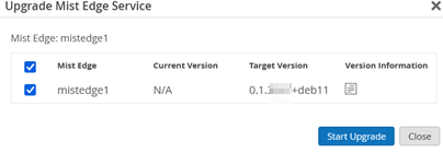
- Perform an update.
- Instead of a DHCP lease, configure a static IP address on the OOBM port.
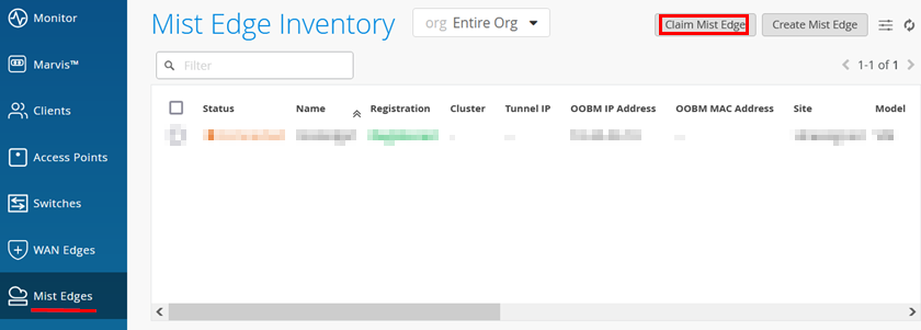
We assume that the Juniper Mist Edge is already connected and powered on in the lab, so we can now create the instance in the Juniper Mist cloud. Go to Mist Edges > Mist Edge Inventory > Claim Mist Edge:
Claim the new Mist Edge like the example shown below:
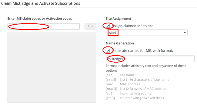
Remember that the claim code is located in the right front bottom of the appliance, and you must extend the pull-out tag to view it:
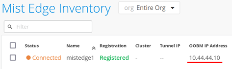
Next, the Juniper Mist Edge should appear as “Connected” and “Registered” in the Juniper Mist Edge inventory and should show the OOBM interface’s DHCP-assigned IP address.
After clicking on the device in the portal, a new page opens. The first task (which may not be needed) is to perform an update as shown below:
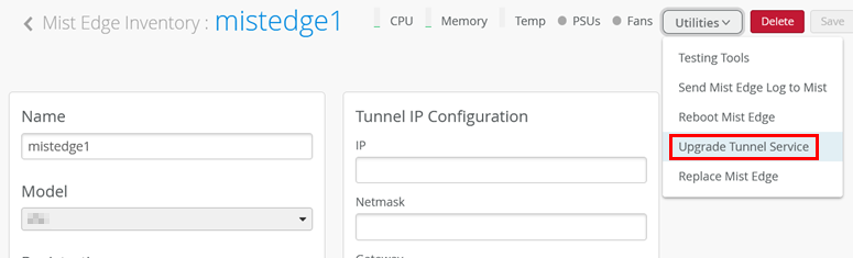
.
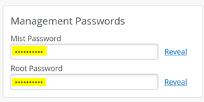
Next, we recommend changing the default management password for the internal Mist and root accounts on the appliance.
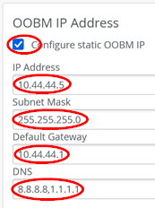
Next, we need to change the dynamic IP address assigned on the OOBM interface to a static IP address since all RADIUS clients expect to reach the RADIUS server using a static IP address. Hence, we configure for our lab:
- Configure static OOBM IP=
Enabled - IP Address=
10.44.44.5 - Subnet Mask=
255.255.255.0 - Default Gateway=
10.44.44.1(our WAN router’s ge-0/0/5 interface) - DNS=
8.8.8.8, 1.1.1.1
Do not forget to save your new configuration.
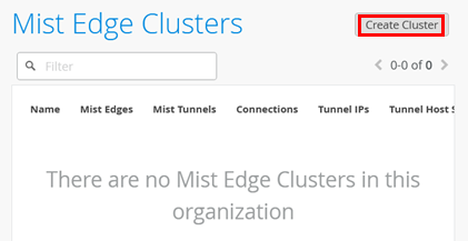
Next, go back one page and select Create Cluster.
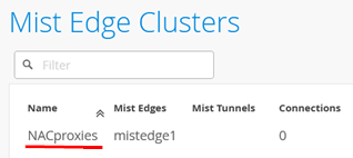
Name the cluster and select the Mist Edge to be a part of it.
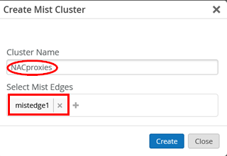
Select the Cluster:
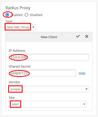
Next, enable the RadSec proxy like in our example:
- Radius Proxy=
Enabled - Type=
Mist NAC Proxy - IP Address=
10.0.0.0/8(We should manage all IP addresses one by one, but not for this lab). - Shared Secret=
juniper123(We should use individual shared secrets, but this is a lab). - Vendor=
juniper(In this case, “Juniper,” but can be a third-party vendor selected from the drop-down menu). - Site=
site1
Do not forget to save your configuration changes.
(Optional) If you prefer, you can open an SSH shell as root to the Juniper Mist Edge device and check locally:
-
root@mistedge1:~# ss -tuln
Netid  State   Recv-Q  Send-Q   Local Address:Port   Peer Address:Port Process
udp    UNCONN  0       0              0.0.0.0:1812        0.0.0.0:*
udp    UNCONN  0       0              0.0.0.0:5355        0.0.0.0:*
udp    UNCONN  0       0        127.0.0.53%lo:53          0.0.0.0:*
udp    UNCONN  0       0              0.0.0.0:68          0.0.0.0:*
udp    UNCONN  0       0                 [::]:1812           [::]:*
udp    UNCONN  0       0                 [::]:5355           [::]:*
tcp    LISTEN  0       128            0.0.0.0:22          0.0.0.0:*
tcp    LISTEN  0       4096         127.0.0.1:9080        0.0.0.0:*
tcp    LISTEN  0       4096           0.0.0.0:5355        0.0.0.0:*
tcp    LISTEN  0       4096         127.0.0.1:9199        0.0.0.0:*
tcp    LISTEN  0       4096         127.0.0.1:9109        0.0.0.0:*
tcp    LISTEN  0       4096     127.0.0.53%lo:53          0.0.0.0:*
tcp    LISTEN  0       128               [::]:22             [::]:*
tcp    LISTEN  0       4096              [::]:5355           [::]:*
root@mistedge1:~# systemctl status radsecproxy
* radsecproxy.service - radsecproxy
     Loaded: loaded (/lib/systemd/system/radsecproxy.service; enabled; vendor p>
    Drop-In: /usr/lib/systemd/system/radsecproxy.service.d
             `-mxedge.conf
     Active: active (running) since Thu 2024-08-15 15:27:29 UTC; 15min ago
       Docs: man:radsecproxy(1)
   Main PID: 1821 (radsecproxy)
         IP: 189.8K in, 128.8K out
         IO: 128.0K read, 72.0K written
      Tasks: 9 (limit: 32768)
     Memory: 1.6M
        CPU: 592ms
     CGroup: /system.slice/radsecproxy.service
             `-1821 /usr/sbin/radsecproxy -c /etc/mxedge-radsecproxy.conf
Aug 15 15:27:29 mistedge1 systemd[1]: Starting radsecproxy...
Aug 15 15:27:29 mistedge1 systemd[1]: Started radsecproxy.
The RadSec tunnel is always created on demand and does not remain permanently open.
Juniper Mist Authentication Cloud Certificate Installation
In this section, we demonstrate installing the certificates needed for the various authentication methods. In Table 2, we highlight the needed certificates per authentication methods and where they need to be installed. Remember that usually the customer PKI is used for all EAP methods where certificates come into play. For the last two methods in Table 2, we reuse the automatic PKI Mist creates for each organization internally for the RadSec tunnels. This makes life easier in cases when deploying certificates rather than getting them from the customer’s PKI.
In the below table, the term “CA-cert” refers to when the customer has multiple levels with intermediate or signing CAs in their PKI. All of these public certificates must be installed for the entire path. The system needs to be able to evaluate the entire path back to the root CA.
| Authentication Method | CA-Certificate in Mist | RADIUS Server in Mist | Client Supplicant CA-Cert | Client Supplicant User/Machine Cert |
|---|---|---|---|---|
| MAB | N/A | N/A | N/A | N/A |
| EAP-TLS | Customer PKI CA-cert | Customer PKI TLS-Server Public/Private | Customer PKI CA-cert | Customer PKI TLS-Client Public/Private |
| EAP-TTLS | Customer PKI CA-cert | Customer PKI TLS-Server Public/Private | Customer PKI CA-cert | N/A |
| EAP-TTLS Mist PKI | Mist PKI CA-cert | Mist PKI internal | Mist PKI CA-cert | N/A |
| EAP-TLS for Mist AP | Mist PKI CA-cert | Mist PKI internal | Mist PKI CA-cert | Mist PKI auto deployed on AP |
Import a Customer CA Certificate
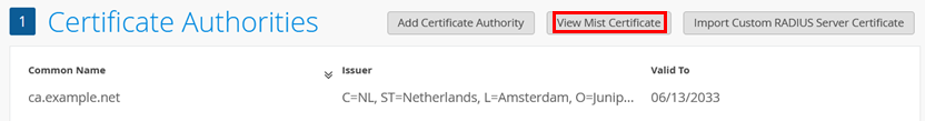
Go to Organization > Certificates to start all processes in this chapter.
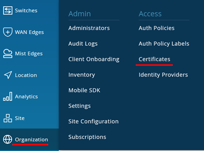
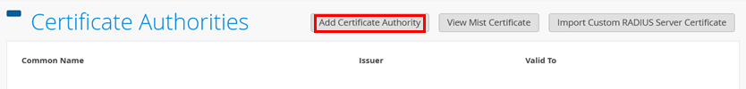
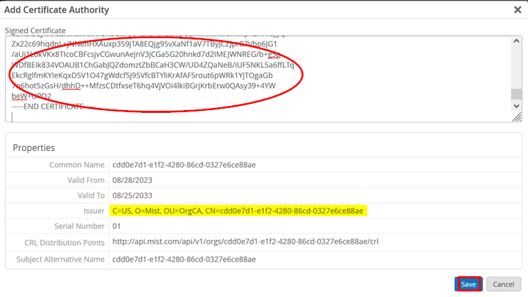
You should see no certificate installed yet, so let’s import the root CA from the customer’s PKI. You need the public part of the certificate in PEM format, then click on Add Certificate Authority:
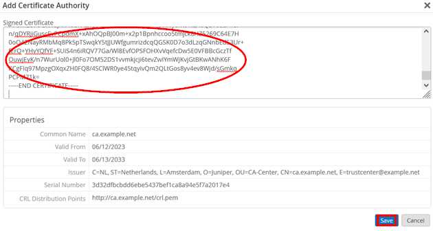
Paste the PEM part of the certificate into the Signed Certificate field. Then, check the extracted properties and then click Save.
Review and Import the Mist CA Certificate
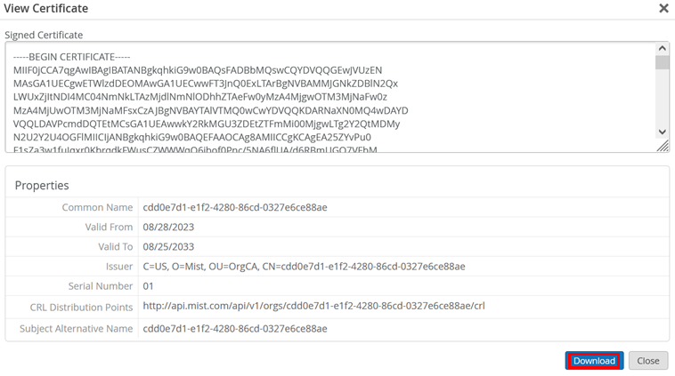
We continue in the same dialogue window and now click on View Mist Certificate:
Inspect the certificate and click on Download to save the certificate locally.
Open the downloaded file and copy the entire contents:
Again, click on Add Certificate Authority:
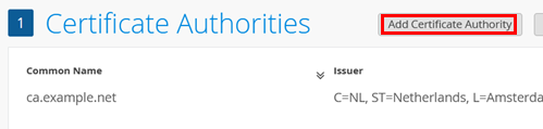
Paste the downloaded contents of the certificate into the Signed Certificate field and click Save:
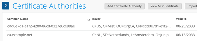
You should now have at least two CA certificates, similar to that shown in the example below:
Import the RADIUS Server Certificates
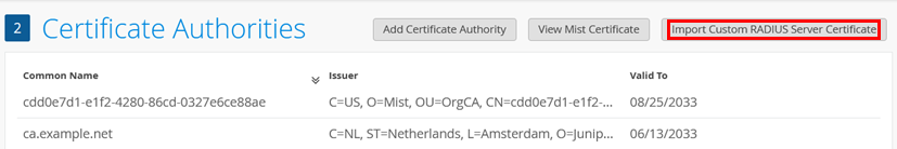
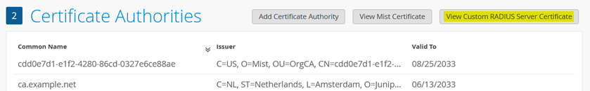
We continue in the same dialogue and check the status of the RADIUS server certificate:
- If the field states Import Customer RADIUS Server Certificate, then nothing is defined yet and the RADIUS server will use a certificate signed by the Mist internal PKI for each organization.
- If the field states View Customer RADIUS Server Certificate, then you have valid customer PKI certificates successfully loaded, which will be used for EAP authentications.
In our example, nothing is defined yet, hence we click on the Import Customer RADIUS Server Certificate button.
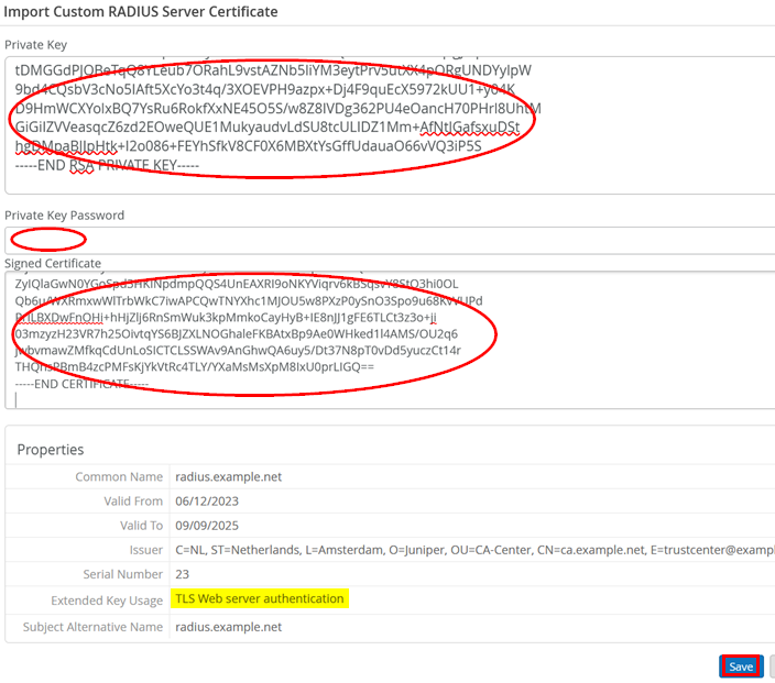
Fill in the fields for Private Key and Signed Certificate. You may also need to add a password under Private Key Password. Once finished, check the information displayed and the properties before you click Save.
Now all required certificate configurations for your lab have been performed.
Configure Client Supplicants with Certificates and Necessary EAP Methods
This chapter has examples of manual client configurations used when no MDM is set up for managing supplicants. This is intended more for test engineers rather than for production-grade deployments where using an MDM is highly recommended. However, it may be good to know what needs to be configured and where.
Again, if you intend to use an MDM of some kind to manage your clients you can skip over this entire chapter.
Installing a Local Certificate on a Windows Client
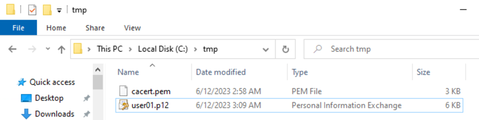
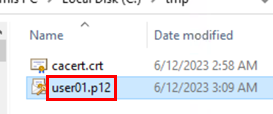
In our example, we use a home-grown certificate PKI. Here, you
can see the folder where the original cacert.pem and
user01.p12 files are located and transferred to the
local device:
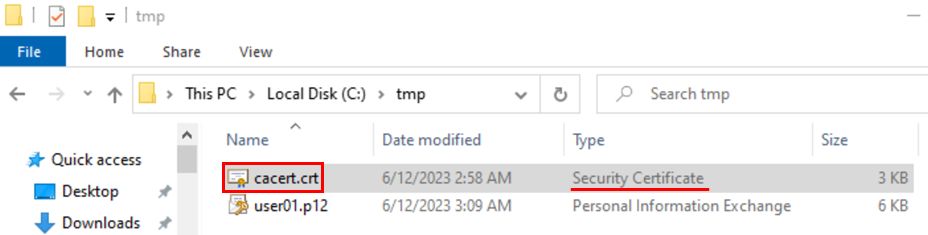
Rename the file cacert.pem to
cacert.crt so that Windows recognizes the correct
type. Then, double-click on the file to import it.
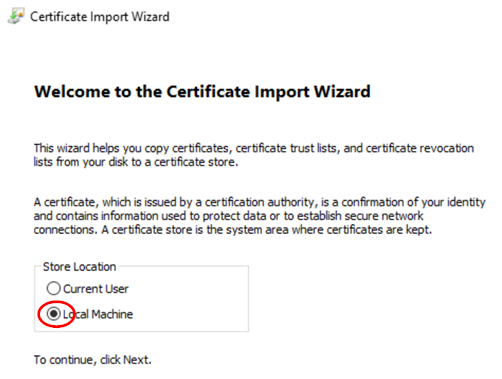
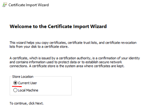
Click on Install Certificate.
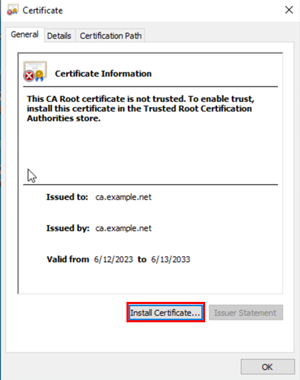
Select Local Machine to be able to share the new root CA with other accounts.
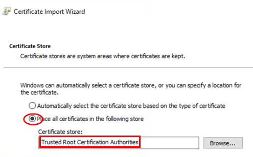
Configure the following settings:
- Place all certificates in the following
store=
Checked - Certificate store=
Trusted Root Certification
Authorities
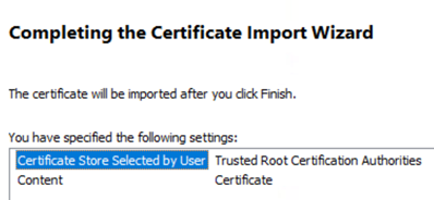
Complete the wizard:
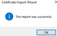
Your certificate should now be imported.
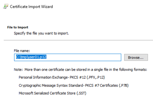
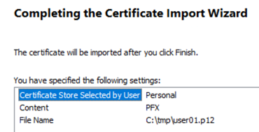
Next, let’s import the User=Certificate by double-clicking
the file user01.p12:
Configure in this dialogue:
- Storage Location=
Current User
Review the file location and name:
Our certificate has the following information:
- Password=
juniper123
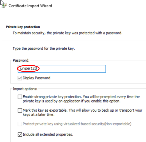
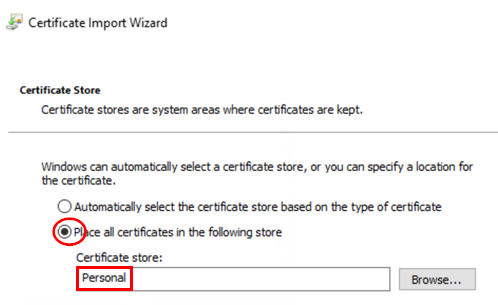
Configure the following settings:
- Place all certificates in the following
store=
Checked - Certificate store=
Personal
Complete the wizard.
Your certificate should now be imported.
.png)
Windows Client Wired EAP-TLS Example
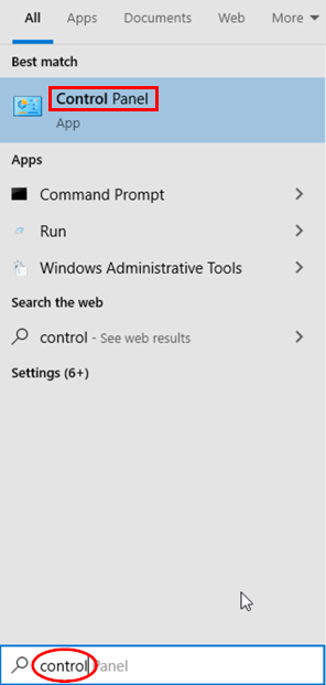
To configure the wired NIC, type the word “control” in the local search field and click Control Panel:
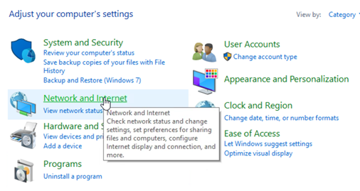
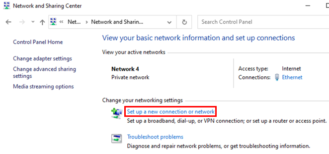
Depending on your view, select Network and Internet:
Depending on your view, select Network and Sharing Center.
There should be at least one ethernet adapter listed under Connections that you can select.
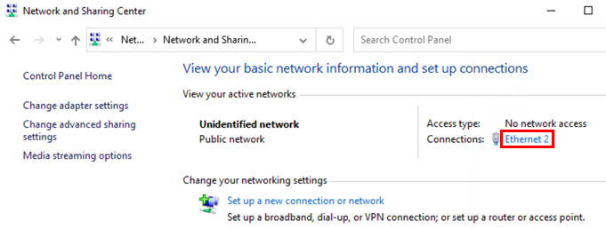
Select the Properties dialogue.
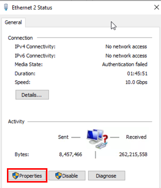
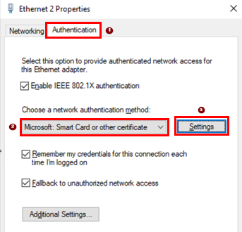
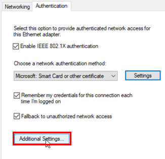
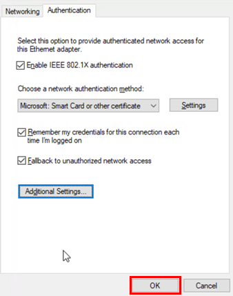
Change to the Authentication tab. Then, configure the following settings:
- Network authentication method=
Microsoft: Smart Card or
other certificate
- Click on=
Settings
The only change in this dialogue is to select the
Trusted Root Certification Authorities which in
our case is ca.example.net. Leave the remaining fields
as their defaults and return to the previous dialogue.

Click on Additional Settings.
Configure the following settings:
- Specify authentication mode=
Checked - Mode=
User authentication
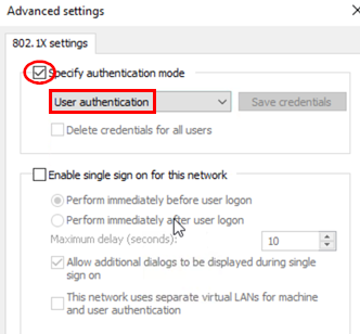
Now, you can finish the main dialogue.
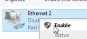
For simple testing, we recommend you first disable the adapter.
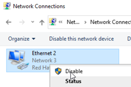
Then, enable the adapter again and check if authentication works.
Windows Client Wireless EAP-TLS Example
To configure the WLAN adapter, type the word “control” in the local search field and click Control Panel.
.png)
Depending on your view, select Network and Internet.
.png)
Depending on your view, select Network and Sharing Center.
.png)
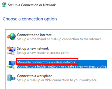
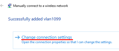
Then, select Set up a new connection or network.
Select Manually connect to a wireless network.
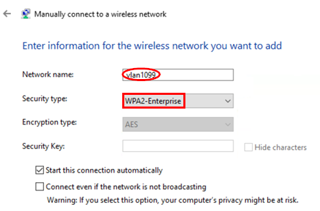
Configure the following settings:
- Network Name=
<SSID> - Security type=
WPA2-Enterprise
. 
Select Change connection settings.
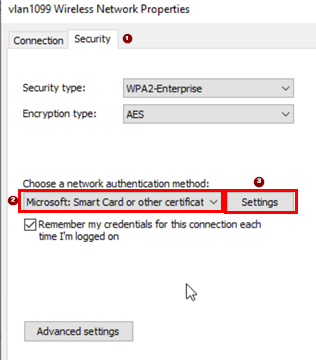
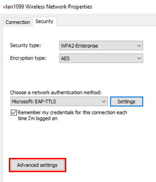
Change to the Security tab. Then, configure the following:
- Network authentication method=
Microsoft: Smart Card or
other certificate
- Click on=
Settings
The only change in this dialogue is to select the
Trusted Root Certification Authorities which in
our case is ca.example.net. Leave the remaining fields
as their defaults and return to the previous dialogue.
.png)
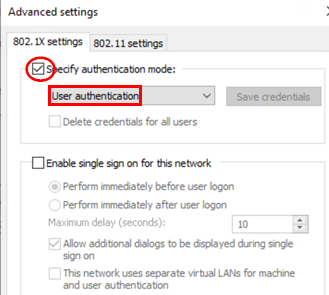
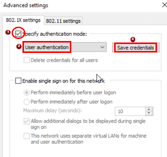
Click on Additional Settings.
.png)
Configure the following settings.
- Specify authentication mode=
Checked - Mode=
User authentication
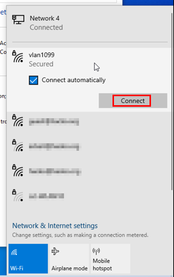
You can now finish the main dialogue. Then, connect to the wireless network using the usual dialogue.
Windows Client Wired EAP-TTLS Example
To configure the wired NIC, type the word “control” in the local search field and click Control Panel.
.png)
Depending on your view, select Network and Internet.
.png)
Depending on your view, select Network and Sharing Center.
.png)
There should be at least one ethernet adapter under Connections that you can select.
.png)
Select the Properties dialogue.
.png)
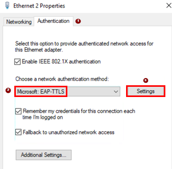
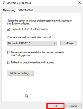
Change to the Authentication tab. Then, configure the following settings:
- Network authentication method=Microsoft:
EAP-TTLS - Click on=
Settings
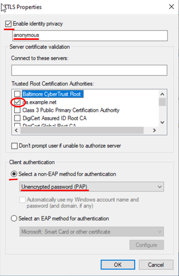
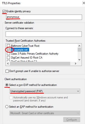
The only change in this dialogue is to select our
Trusted Root Certification Authorities, which in
our case is ca.example.net. Leave the remaining fields
as their defaults and return to the previous dialogue. Make sure
the client authentication method is the default Unencrypted
password (PAP).
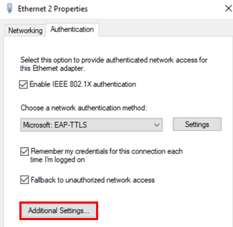
Click on Additional Settings.
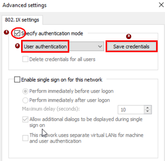
Configure the following settings:
- Specify authentication mode=
Checked - Mode=
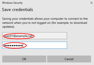
User authentication - Click-on=
Save credentials
Next, enter a username and password that is valid for the remote IdP the Juniper Mist Authentication cloud will contact for validation. In our case, with the example PKI, enter the following:
- Username=
user01@example.net - Password=
juniper123
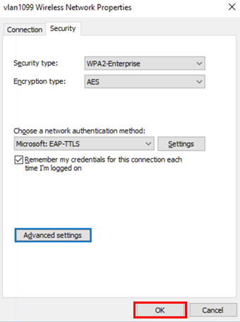
Then, save this dialogue and return to the previous one.
You can now finish the main dialogue.
For simple testing, we recommend you first disable the adapter.
.png)
Then, enable the adapter back again and check if authentication works.
.png)
Windows Client Wireless EAP-TTLS Example
To configure the WLAN adapter, type the word “control” in the local search field and click Control Panel.
.png)
Depending on your view, click on Network and Internet.
.png)
Depending on your view, click on Network and Sharing Center.
.png)
Click on Set up a new connection or network.
.png)
Select Manually connect to a wireless network.
.png)
Configure the following settings:
- Network Name=
<SSID> - Security type=
WPA2-Enterprise
.png)
Select Change connection settings.
.png)
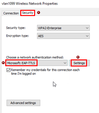
Change to the Security tab. Then, configure the following settings:
- Network authentication method=
Microsoft: Smart Card or
other certificate
- Click on=
Settings
The only change in this dialogue is to select our
Trusted Root Certification Authorities, which in
our case is ca.example.net. Leave the remaining fields
as their defaults and return to the previous dialogue. Make sure
the client authentication method is the default Unencrypted
password (PAP).
Click on Additional Settings.
Configure the following settings.
- Specify authentication mode=
Checked - Mode=
User authentication - Click-on=
Save credentials
Next, enter a username and password that is valid for the remote IdP the Juniper Mist authentication cloud will contact for validation. In our case, with the example PKI, enter the following:
- Username=
user01@example.net - Password=
juniper123
Then, save this dialogue and return to the previous one.
.png)
You can now finish the main dialogue.
Next, connect to the wireless network using the usual dialogue.
.png)
Linux Desktop Client
Linux does not support a dedicated certificate storage. We just
transfer the files onto the system and make them known in the
/etc/wpa_supplicant/wpa_supplicant.conf file which
also contains the EAP authentication method configuration. In the
examples in this chapter, we always perform the following when
testing:
- Login to a desktop client VM.
- Load the required certificates from external storage.
- Write a new file with our configuration into
/etc/wpa_supplicant/wpa_supplicant.conf - Start the EAP supplicant in the foreground to see any debugging messages.
When using EAP-TLS, the user certificate also contains the entire path to the root CA, hence no extra configuration is needed.
Linux Client Wired EAP-TLS Example
In our example, ens5 is the ethernet interface.
              virsh console desktop1
# load your pkcs user-file from Lab-Host into VM
scp root@192.168.10.1:examplePKI/user01.p12 .
# configure the WPA-Supplicant for EAP-TLS
cat <<EOF >/etc/wpa_supplicant/wpa_supplicant.conf
ctrl_interface=DIR=/var/run/wpa_supplicant
ctrl_interface_group=wheel
eapol_version=2
ap_scan=0
network={
   key_mgmt=IEEE8021X
   eap=TLS
   identity="user01@example.net"
   private_key="/root/user01.p12"
   private_key_passwd="juniper123"
   eapol_flags=0
}
EOF
# now start the wpa-supplicant in forground to see its messages
wpa_supplicant -c /etc/wpa_supplicant/wpa_supplicant.conf -D wired -i ens5
Successfully initialized wpa_supplicant
ens5: Associated with 01:80:c2:00:00:03
ens5: CTRL-EVENT-SUBNET-STATUS-UPDATE status=0
ens5: CTRL-EVENT-EAP-STARTED EAP authentication started
ens5: CTRL-EVENT-EAP-PROPOSED-METHOD vendor=0 method=13
ens5: CTRL-EVENT-EAP-METHOD EAP vendor 0 method 13 (TLS) selected
ens5: CTRL-EVENT-EAP-PEER-CERT depth=1 subject='/C=NL/ST=Netherlands/L=Amsterdam/O=Juniper/OU=CA-Center/CN=ca.example.net/emailAddress=trustcenter@example.net' hash=6474bda8fe419b2525f6efa3579d2947437bc08e1a8ded9d48724f610c7c50e5
ens5: CTRL-EVENT-EAP-PEER-CERT depth=1 subject='/C=NL/ST=Netherlands/L=Amsterdam/O=Juniper/OU=CA-Center/CN=ca.example.net/emailAddress=trustcenter@example.net' hash=6474bda8fe419b2525f6efa3579d2947437bc08e1a8ded9d48724f610c7c50e5
ens5: CTRL-EVENT-EAP-PEER-CERT depth=0 subject='/C=US/ST=California/O=Example TEST-Corp./OU=IT-Department/CN=radius.example.net' hash=3fa3a749a49e49597c3fd9b2441f0c4ce6ab4e9e792868ac94a82fe69f0768c9
ens5: CTRL-EVENT-EAP-PEER-ALT depth=0 DNS:radius.example.net
ens5: CTRL-EVENT-EAP-SUCCESS EAP authentication completed successfully
ens5: CTRL-EVENT-CONNECTED - Connection to 01:80:c2:00:00:03 completed [id=0 id_str=]
Linux Client Wireless EAP-TLS Example
              virsh console desktop2
# load your pkcs user-file from Lab-Host into VM
scp root@192.168.10.1:examplePKI/user01.p12 .
# configure the WPA-Supplicant for EAP-TLS
cat <<EOF >/etc/wpa_supplicant/wpa_supplicant.conf
ctrl_interface=DIR=/var/run/wpa_supplicant
ctrl_interface_group=wheel
eapol_version=2
ap_scan=1
network={
   ssid="vlan1099"               # SSID of the network to connect
   scan_ssid=1                   # enable probe request for finding networks using hidden SSID
   key_mgmt=WPA-EAP              # use external authentication, not pre-shared key
   eap=TLS
   identity="user01@example.net"
   private_key="/root/user01.p12"
   private_key_passwd="juniper123"
   eapol_flags=0
}
EOF
# check how your WLAN USB-Adapter is named
iwconfig
lo        no wireless extensions.
wlxe8de27a0e68e  IEEE 802.11  ESSID:off/any
          Mode:Managed  Access Point: Not-Associated   Tx-Power=20 dBm
          Retry short limit:7   RTS thr=2347 B   Fragment thr:off
          Encryption key:off
          Power Management:off
ens3      no wireless extensions.
# now start the wpa-supplicant in forground to see its messages
rm -f /var/run/wpa_supplicant/wlxe8de27a0e68e
              wpa_supplicant -c /etc/wpa_supplicant/wpa_supplicant.conf -D nl80211 -i wlxe8de27a0e68e
Successfully initialized wpa_supplicant
wlxe8de27a0e68e: SME: Trying to authenticate with d4:20:b0:11:56:13 (SSID='vlan1099' freq=2462 MHz)
wlxe8de27a0e68e: Trying to associate with d4:20:b0:11:56:13 (SSID='vlan1099' freq=2462 MHz)
wlxe8de27a0e68e: Associated with d4:20:b0:11:56:13
wlxe8de27a0e68e: CTRL-EVENT-EAP-STARTED EAP authentication started
wlxe8de27a0e68e: CTRL-EVENT-SUBNET-STATUS-UPDATE status=0
wlxe8de27a0e68e: CTRL-EVENT-REGDOM-CHANGE init=COUNTRY_IE type=COUNTRY alpha2=US
wlxe8de27a0e68e: CTRL-EVENT-EAP-STARTED EAP authentication started
wlxe8de27a0e68e: CTRL-EVENT-EAP-PROPOSED-METHOD vendor=0 method=13
wlxe8de27a0e68e: CTRL-EVENT-EAP-METHOD EAP vendor 0 method 13 (TLS) selected
wlxe8de27a0e68e: CTRL-EVENT-EAP-PEER-CERT depth=1 subject='/C=NL/ST=Netherlands/L=Amsterdam/O=Juniper/OU=CA-Center/CN=ca.example.net/emailAddress=trustcenter@example.net' hash=6474bda8fe419b2525f6efa3579d2947437bc08e1a8ded9d48724f610c7c50e5
wlxe8de27a0e68e: CTRL-EVENT-EAP-PEER-CERT depth=1 subject='/C=NL/ST=Netherlands/L=Amsterdam/O=Juniper/OU=CA-Center/CN=ca.example.net/emailAddress=trustcenter@example.net' hash=6474bda8fe419b2525f6efa3579d2947437bc08e1a8ded9d48724f610c7c50e5
wlxe8de27a0e68e: CTRL-EVENT-EAP-PEER-CERT depth=0 subject='/C=US/ST=California/O=Example TEST-Corp./OU=IT-Department/CN=radius.example.net' hash=3fa3a749a49e49597c3fd9b2441f0c4ce6ab4e9e792868ac94a82fe69f0768c9
wlxe8de27a0e68e: CTRL-EVENT-EAP-PEER-ALT depth=0 DNS:radius.example.net
wlxe8de27a0e68e: CTRL-EVENT-EAP-SUCCESS EAP authentication completed successfully
wlxe8de27a0e68e: PMKSA-CACHE-ADDED d4:20:b0:11:56:13 0
wlxe8de27a0e68e: WPA: Key negotiation completed with d4:20:b0:11:56:13 [PTK=CCMP GTK=CCMP]
wlxe8de27a0e68e: CTRL-EVENT-CONNECTED - Connection to d4:20:b0:11:56:13 completed [id=0 id_str=]
Linux Client Wired EAP-TTLS Example
In our example, ens5 is the ethernet interface:
              virsh console desktop1
# load your root-ca-file from Lab-Host into VM
scp root@192.168.10.1:examplePKI/cacert.pem .
# configure the WPA-Supplicant for EAP-TTLS w. PAP
cat <<EOF >/etc/wpa_supplicant/wpa_supplicant.conf
ctrl_interface=DIR=/var/run/wpa_supplicant
ctrl_interface_group=wheel
ap_scan=0
network={
  key_mgmt= IEEE8021X           # use external authentication, not pre-shared key
  eap=TTLS                      # enable TTLS method for encrypted tunnel
  ca_cert="/root/cacert.pem"    # root-ca that signed the cert of the AAA-Server
  anonymous_identity="anon@example.net"    # use identity outside tunnel as NAI
  phase2="auth=PAP"             # use password authentication protocol
                                # this will pass clear-text password inside tunnel
  identity="user01@example.net" # use this identity inside tunnel
  password="juniper123"         # password of the authenticating user
}
EOF
# now start the wpa-supplicant in forground to see its messages
wpa_supplicant -c /etc/wpa_supplicant/wpa_supplicant.conf -D wired -i ens5
Successfully initialized wpa_supplicant
ens5: Associated with 01:80:c2:00:00:03
ens5: CTRL-EVENT-SUBNET-STATUS-UPDATE status=0
ens5: CTRL-EVENT-EAP-STARTED EAP authentication started
ens5: CTRL-EVENT-EAP-PROPOSED-METHOD vendor=0 method=13 -> NAK
ens5: CTRL-EVENT-EAP-PROPOSED-METHOD vendor=0 method=21
ens5: CTRL-EVENT-EAP-METHOD EAP vendor 0 method 21 (TTLS) selected
ens5: CTRL-EVENT-EAP-PEER-CERT depth=1 subject='/C=NL/ST=Netherlands/L=Amsterdam/O=Juniper/OU=CA-Center/CN=ca.example.net/emailAddress=trustcenter@example.net' hash=6474bda8fe419b2525f6efa3579d2947437bc08e1a8ded9d48724f610c7c50e5
ens5: CTRL-EVENT-EAP-PEER-CERT depth=0 subject='/C=US/ST=California/O=Example TEST-Corp./OU=IT-Department/CN=radius.example.net' hash=3fa3a749a49e49597c3fd9b2441f0c4ce6ab4e9e792868ac94a82fe69f0768c9
ens5: CTRL-EVENT-EAP-PEER-ALT depth=0 DNS:radius.example.net
ens5: CTRL-EVENT-EAP-SUCCESS EAP authentication completed successfully
ens5: CTRL-EVENT-CONNECTED - Connection to 01:80:c2:00:00:03 completed [id=0 id_str=]
Linux Client Wireless EAP-TTLS Example
              virsh console desktop2
# load your root-ca-file from Lab-Host into VM
scp root@192.168.10.1:examplePKI/cacert.pem .
# configure the WPA-Supplicant for EAP-TTLS w. PAP
cat <<EOF >/etc/wpa_supplicant/wpa_supplicant.conf
ctrl_interface=DIR=/var/run/wpa_supplicant
ctrl_interface_group=wheel
ap_scan=1
network={
  ssid="vlan1099"               # SSID of the network to connect
  scan_ssid=1                   # enable probe request for finding networks using hidden SSID
  key_mgmt=WPA-EAP              # use external authentication, not pre-shared key
  eap=TTLS                      # enable TTLS method for encrypted tunnel
  ca_cert="/root/cacert.pem"    # root-ca that signed the cert of the AAA-Server
  anonymous_identity="anon@example.net"    # use identity outside tunnel as NAI
  phase2="auth=PAP"             # use password authentication protocol
                                # this will pass clear-text password inside tunnel
  identity="user01@example.net" # use this identity inside tunnel
  password="juniper123"         # password of the authenticating user
}
EOF
# check how your WLAN USB-Adapter is named
iwconfig
lo        no wireless extensions.
wlxe8de27a0e68e  IEEE 802.11  ESSID:off/any
          Mode:Managed  Access Point: Not-Associated   Tx-Power=20 dBm
          Retry short limit:7   RTS thr=2347 B   Fragment thr:off
          Encryption key:off
          Power Management:off
ens3      no wireless extensions.
# now start the wpa-supplicant in forground to see its messages
rm -f /var/run/wpa_supplicant/wlxe8de27a0e68e
              wpa_supplicant -c /etc/wpa_supplicant/wpa_supplicant.conf -D nl80211 -i wlxe8de27a0e68e
Successfully initialized wpa_supplicant
wlxe8de27a0e68e: SME: Trying to authenticate with d4:20:b0:11:56:13 (SSID='vlan1099' freq=2437 MHz)
wlxe8de27a0e68e: Trying to associate with d4:20:b0:11:56:13 (SSID='vlan1099' freq=2437 MHz)
wlxe8de27a0e68e: Associated with d4:20:b0:11:56:13
wlxe8de27a0e68e: CTRL-EVENT-EAP-STARTED EAP authentication started
wlxe8de27a0e68e: CTRL-EVENT-SUBNET-STATUS-UPDATE status=0
wlxe8de27a0e68e: CTRL-EVENT-REGDOM-CHANGE init=COUNTRY_IE type=COUNTRY alpha2=US
wlxe8de27a0e68e: CTRL-EVENT-EAP-PROPOSED-METHOD vendor=0 method=13 -> NAK
wlxe8de27a0e68e: CTRL-EVENT-EAP-PROPOSED-METHOD vendor=0 method=21
wlxe8de27a0e68e: CTRL-EVENT-EAP-METHOD EAP vendor 0 method 21 (TTLS) selected
wlxe8de27a0e68e: CTRL-EVENT-EAP-PEER-CERT depth=1 subject='/C=NL/ST=Netherlands/L=Amsterdam/O=Juniper/OU=CA-Center/CN=ca.example.net/emailAddress=trustcenter@example.net' hash=6474bda8fe419b2525f6efa3579d2947437bc08e1a8ded9d48724f610c7c50e5
wlxe8de27a0e68e: CTRL-EVENT-EAP-PEER-CERT depth=0 subject='/C=US/ST=California/O=Example TEST-Corp./OU=IT-Department/CN=radius.example.net' hash=3fa3a749a49e49597c3fd9b2441f0c4ce6ab4e9e792868ac94a82fe69f0768c9
wlxe8de27a0e68e: CTRL-EVENT-EAP-PEER-ALT depth=0 DNS:radius.example.net
wlxe8de27a0e68e: CTRL-EVENT-EAP-SUCCESS EAP authentication completed successfully
wlxe8de27a0e68e: PMKSA-CACHE-ADDED d4:20:b0:11:56:13 0
wlxe8de27a0e68e: WPA: Key negotiation completed with d4:20:b0:11:56:13 [PTK=CCMP GTK=CCMP]
wlxe8de27a0e68e: CTRL-EVENT-CONNECTED - Connection to d4:20:b0:11:56:13 completed [id=0 id_str=]
Configuration Examples of Public Identity Provider Database Integration
Azure AD Integration
Juniper Mist Access Assurance allows you to integrate our authentication service natively into Azure Active Directory using OAuth. Then, you leverage Azure AD as an IdP in combination with Juniper Mist Access Assurance in the following way:
- User authentication with EAP-TTLS
- Authenticate users by doing delegated authentication checking username and password via OAuth
- Obtain user group memberships to leverage them in auth policies
- Obtain user account state information (active or suspended)
- User authorization with EAP-TLS or EAP-TTLS
- Obtain user account state information (active or suspended)
- Obtain user group memberships to leverage them in auth policies
- User authorization status by MDM compliance status (using Microsoft Intune)
Azure AD Integration Part 1: Azure Portal configuration
Login to your Azure tenant at portal.azure.com.
Navigate to Azure Active Directory > App Registrations.
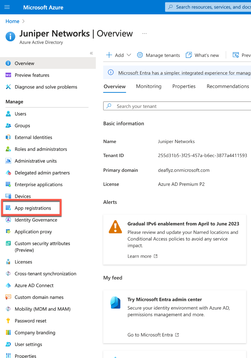
Click on New Registration.
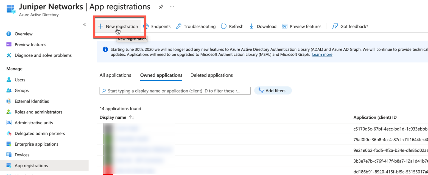
Give your application a name, then click Register.
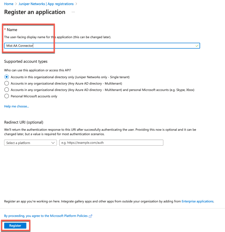
Copy and save Application (client) ID, Directory (tenant) ID, then select Add a certificate or secret.
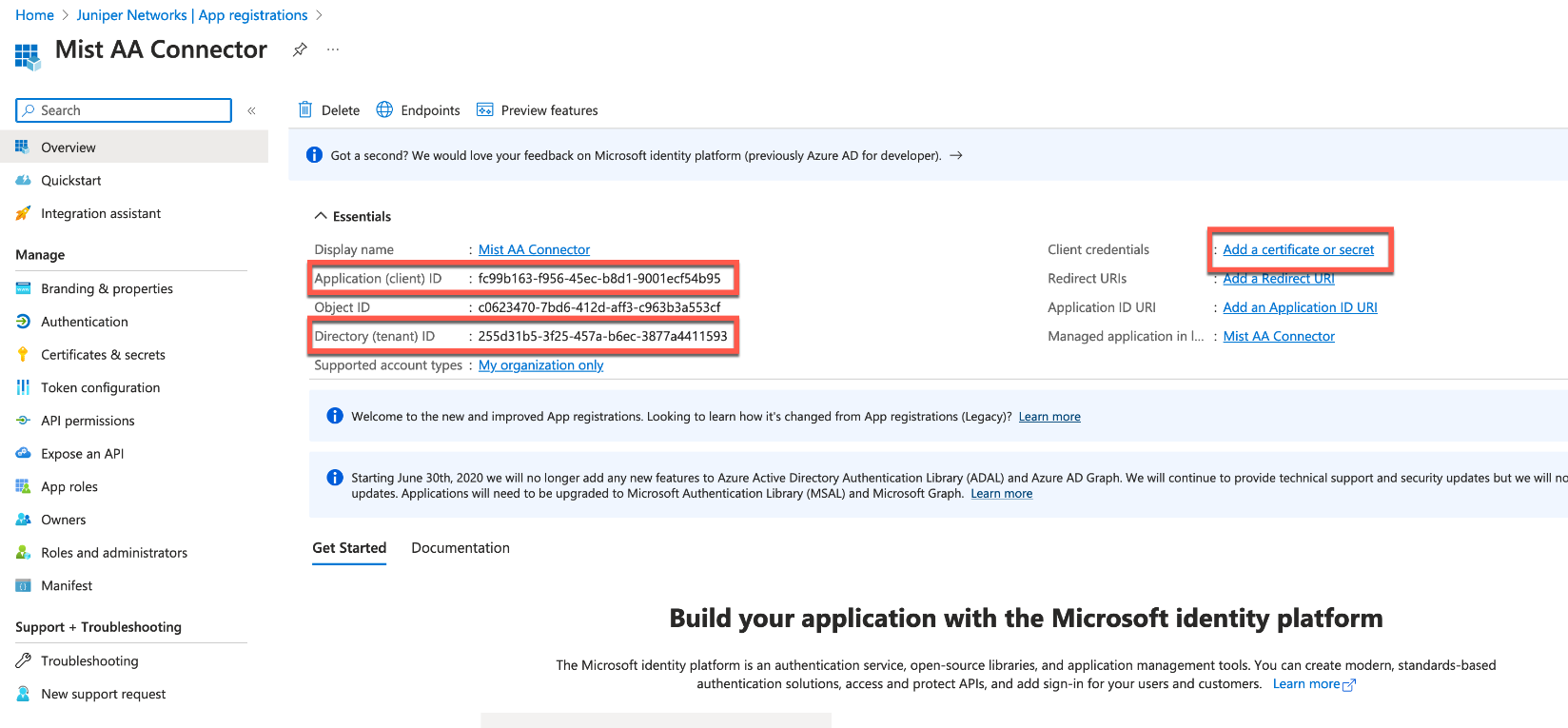
Select New Client Secret, set the secret expiration, then click Add.
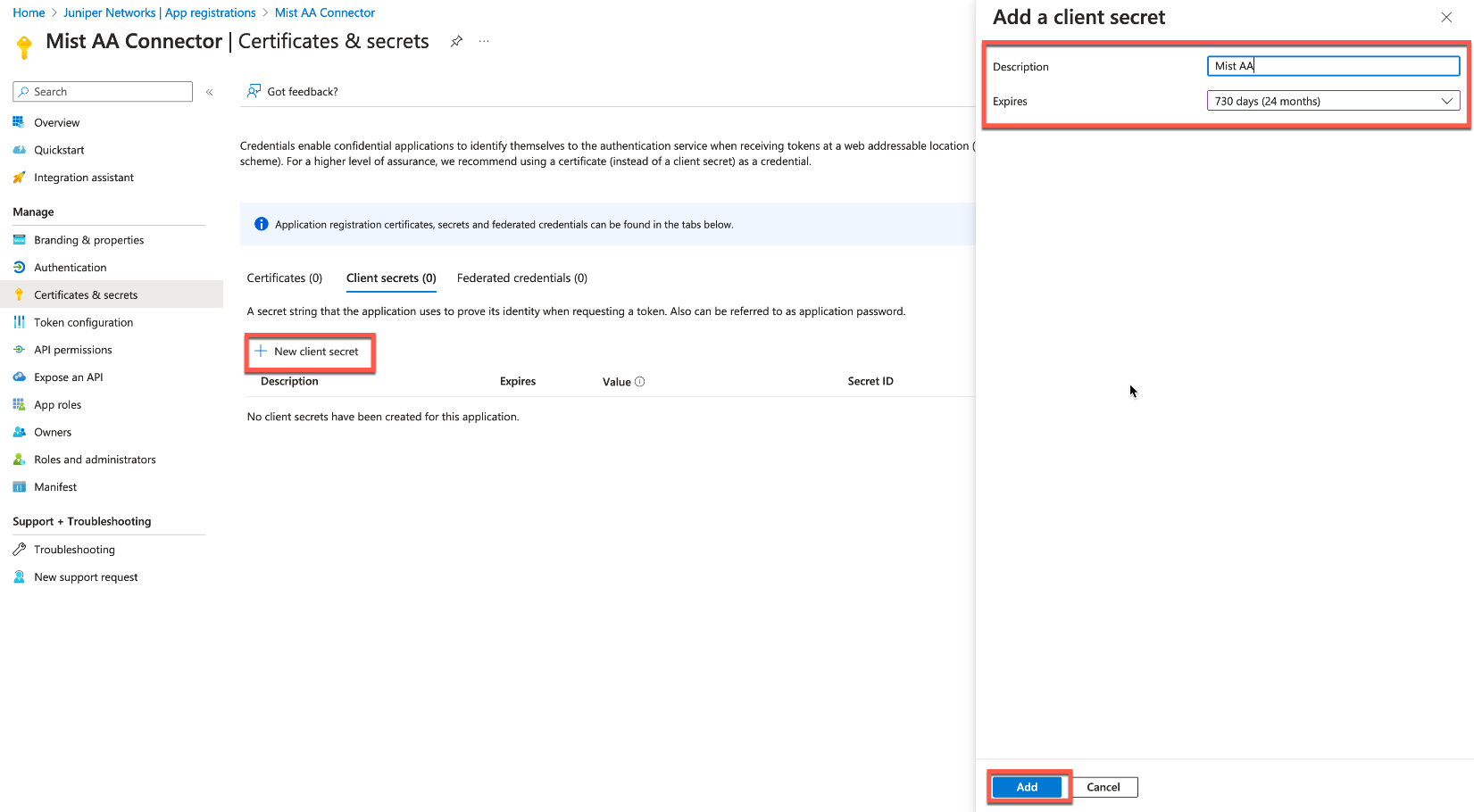
Once the secret is added, copy and save the Value field (note that you will only see it once immediately after the secret is created, so make sure to save it in a secure place).

Now, navigate to the Authentication tab and enable Allow public client flows, this is required if you want to support EAP-TTLS credential-based authentication.
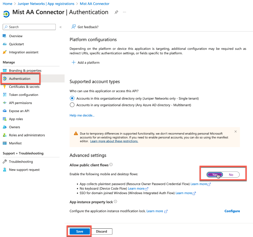
Lastly, navigate to the API permissions tab and grant the following permissions, and do not forget to grant admin consent:
Microsoft Graph:
- User.Read=
Delegated - User.Read.All=
Application - Group.Read.All=
Application
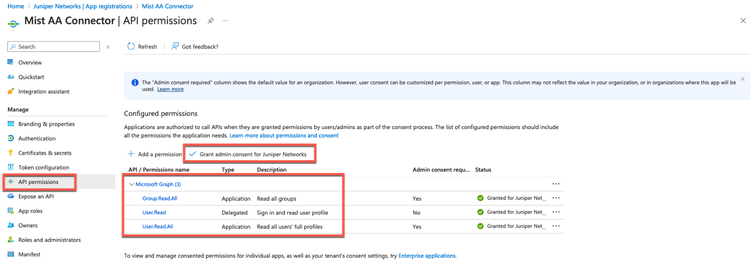
Azure AD Integration Part 2: Juniper Mist Cloud Configuration
Navigate to Organization > Access > Identity Providers and click Add IDP.
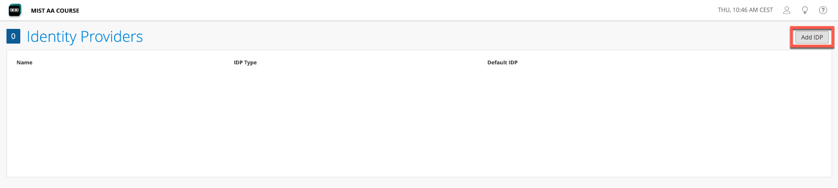
Configure Azure AD integration as follows:
- IDP Type=
OAuth - OAuth Type=
Azure - OAuth Tenant ID=
<paste value from Directory (tenant)
ID you copied from Azure app>
- Domain Names=
<configure your Azure domain
name(s)>
- OAuth Client Credential (CC) Client Id:=
<paste
Application (client) ID you copied from Azure app
earlier>
- OAuth Client Credential (CC) Client Secret=
<paste
Value of the secret your created earlier>
- OAuth ROPC Client Id=
<paste Application (client) ID
from Azure>
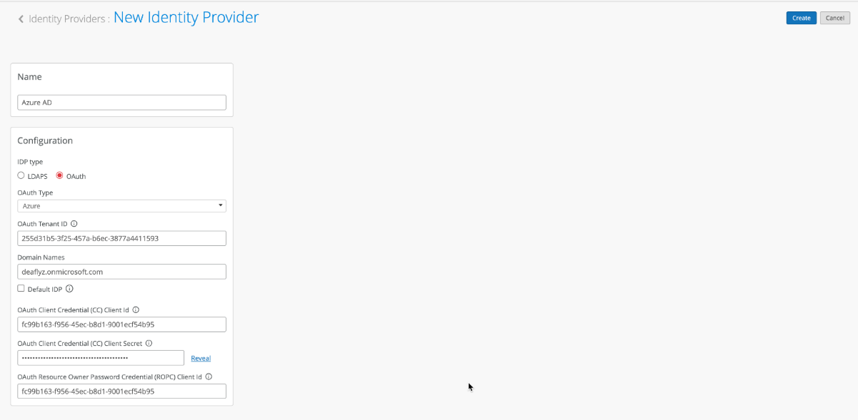
Notes on EAP-TTLS authentication with Azure.
EAP-TTLS authentication leverages Resource Owner Password Credential (ROPC) OAuth flow with Azure AD, which means using legacy authentication using a username and password without multi-factor authentication (MFA). Below are a few considerations to keep in mind regarding using this method:
- Client devices need to be configured with the right Wi-Fi profile, either from group policy (GPO) or MDM—simply providing a username and password at the login prompt will not work for some operating systems.
- Users need to use their full user principal name (UPN) (username@domain), not just their username.
- Clients need to trust the server certificate. See following document for more details.
- Users need to log in at least once to Azure before ROPC authentication will work (this is important if using test user accounts).
- MFA needs to be disabled for users using this specific application, as MFA is not a real option for 802.1X (breaks roaming, and client timeouts).
Validation
When clients are authenticated using EAP-TLS with Azure AD lookup, you should see an additional event called NAC IDP Group Lookup Success.
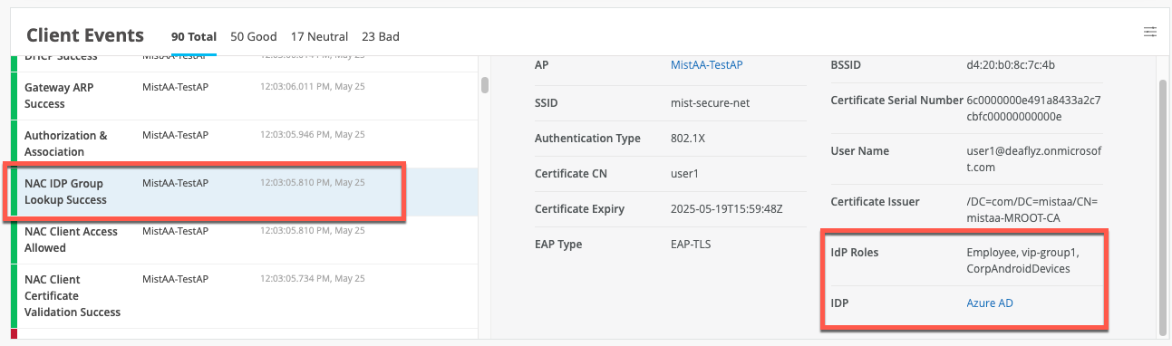
In EAP-TTLS scenarios, you should see NAC IDP Authentication Success (indicating that Azure validated the user credentials), followed by a NAC IDP Group Lookup Success event that fetches user group memberships.
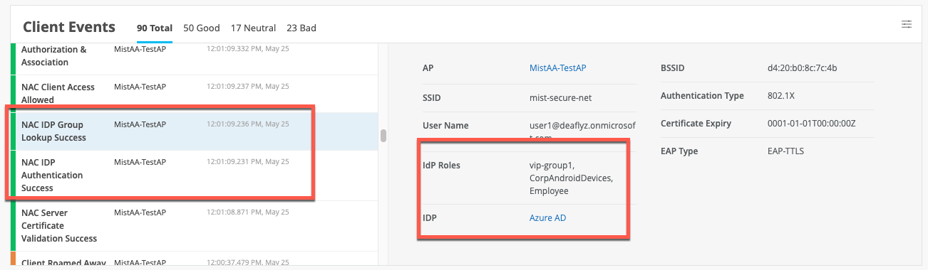
Okta Integration
Juniper Mist Access Assurance allows you to integrate our authentication service natively with the Okta directory using OAuth. Then, you leverage Okta as the IdP in combination with Juniper Mist Access Assurance in the following way:
- User authentication with EAP-TTLS
- Authenticate the user by doing delegated authentication checking username and password via OAuth
- Obtain user group memberships to leverage them in auth policies
- Obtain user account state information (active or suspended)
- User authorization with EAP-TLS or EAP-TTLS
- Obtain user account state information (active or suspended)
- Obtain user group memberships to leverage them in auth policies
Okta Integration Part 1: Okta Dashboard
First, get your Okta tenant ID and save it. You can see it if you click in the upper-right corner of the Okta dashboard:
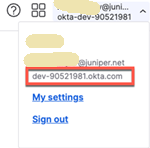
Okta Integration Part 2: OKTA Resource Owner Password Credential App Integration
The steps in this section are for the IdP to be able to validate the User credentials when asked by the Mist Authentication Cloud.
Step 1—Create App Integration
Navigate to Applications > Create New App Integration.
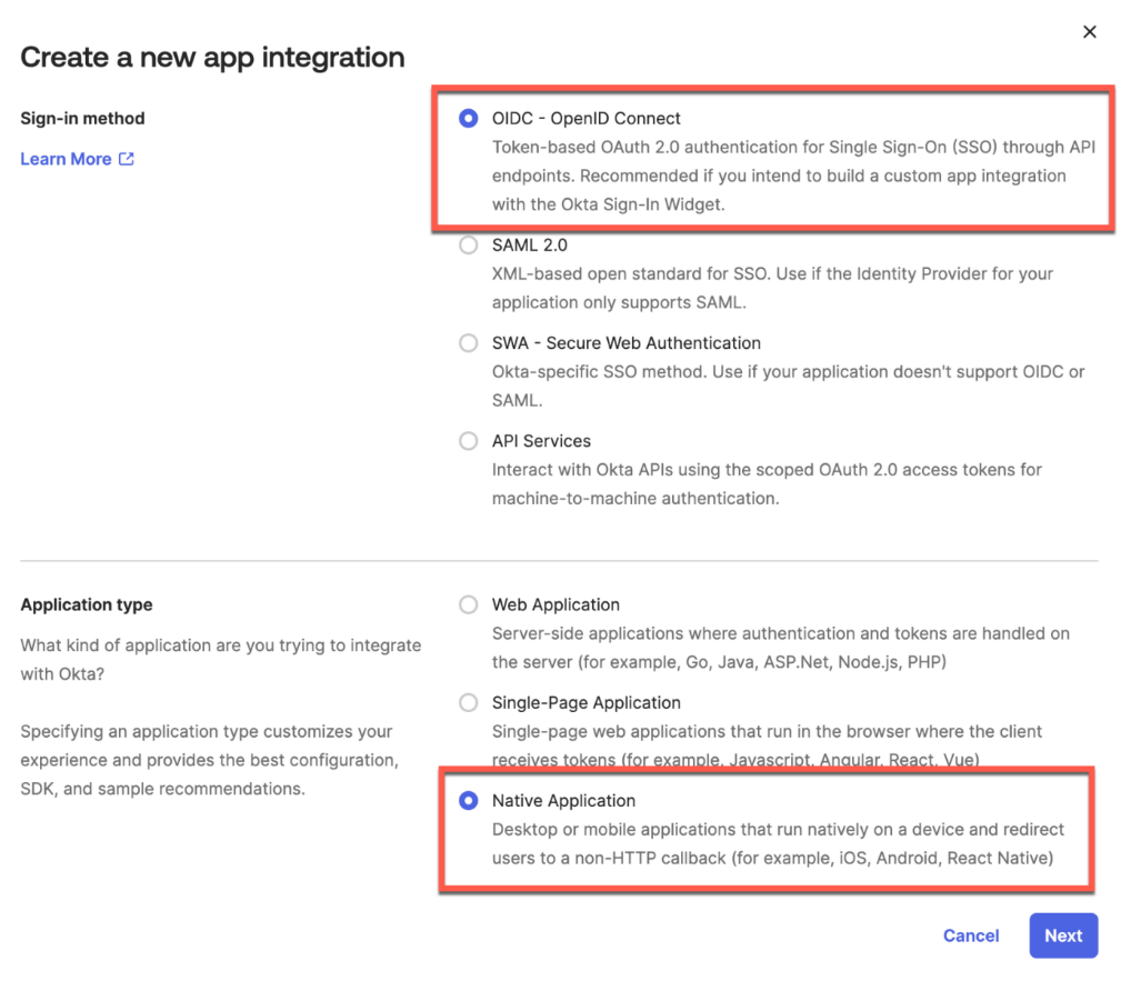
Step 2—Configure App Grant type and user assignments
Name your application, select Resource Owner Password grant type:
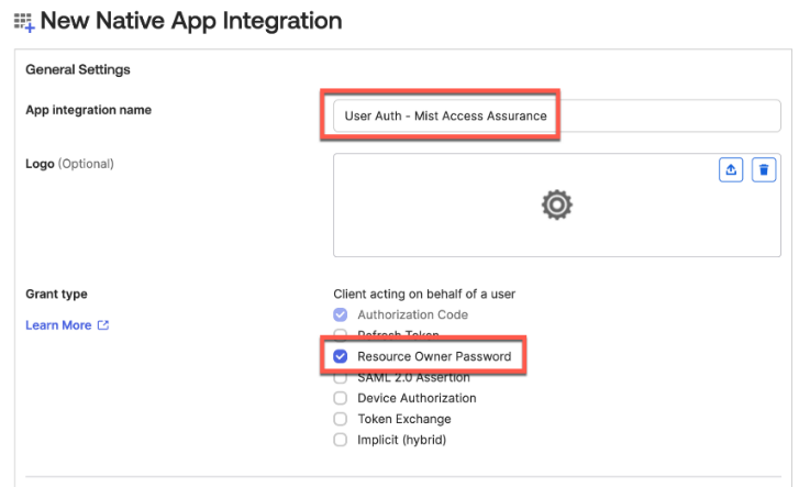
Select which users to allow to authenticate with this app.
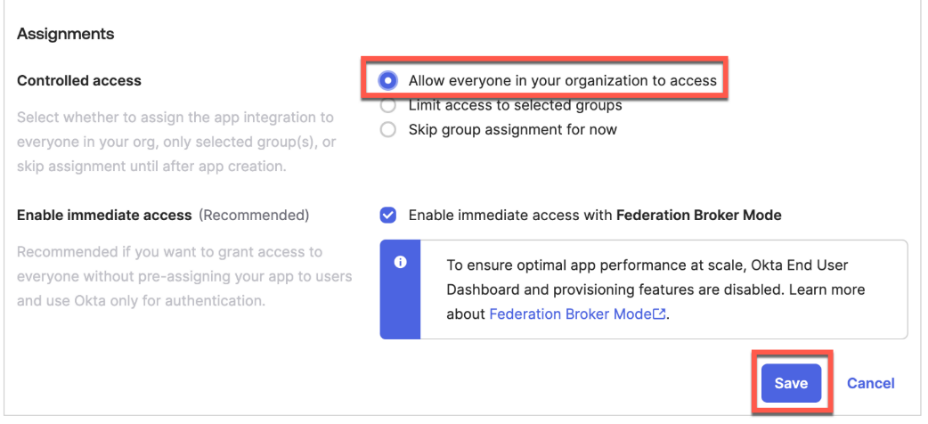
Step 3—Generate Client ID and Client Secret
Let’s generate the client secret. Under the General tab, click on the Edit button.
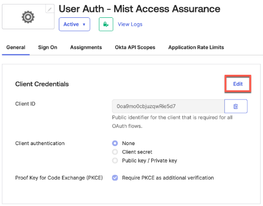
Set Client Authentication as Client Secret.
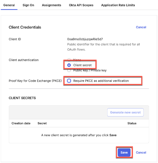
Copy the generated client ID and client secret.
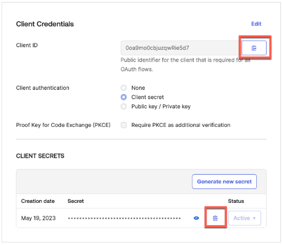
Step 4—Configure App API Scopes
Go to the Okta API scopes to allow the app the following read permissions.
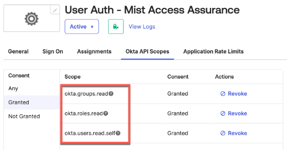
Okta Integration Part 3: OKTA Client Credential App Integration
The steps in this section are for the IdP to send back group assignments to the Mist Authentication cloud after successful user authentication.
Step 1—Create the App Integration
Navigate to Applications > Create New App Integration. Select API Services as the sign-in method.
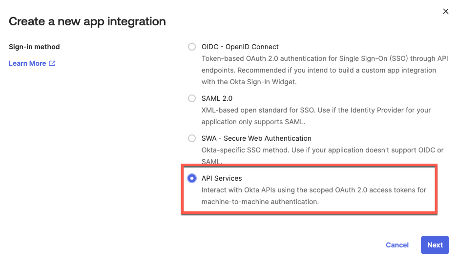
Name your application and click Save.
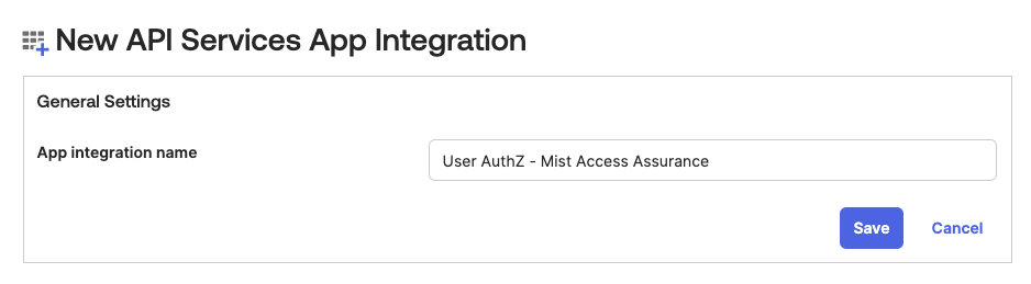
Step 2—Generate the Client ID and Private Key
On the next screen, select Edit to generate a private key.
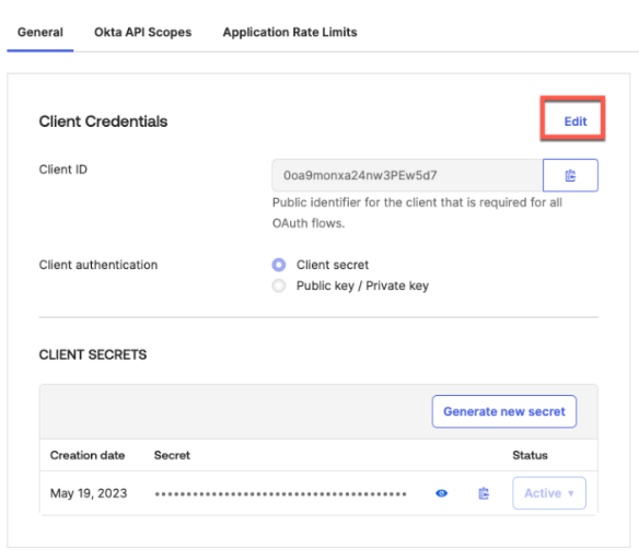
Set Client Authentication as Public key / Private key, then click on Add key.
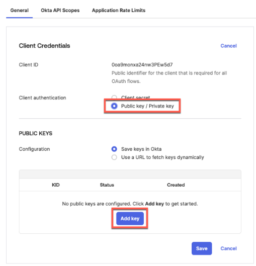
First, select PEM as the format, then click Copy to clipboard to copy the resulting private key (save it in a secure place), then click Done.
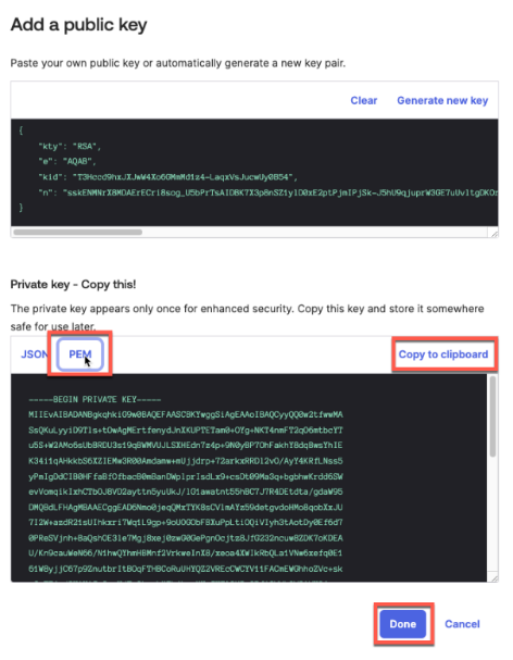
On the next screen, click Save.
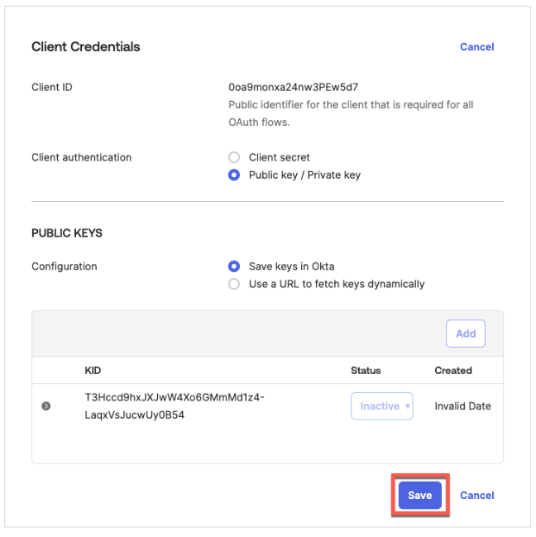
Do not forget to copy and save your client ID.
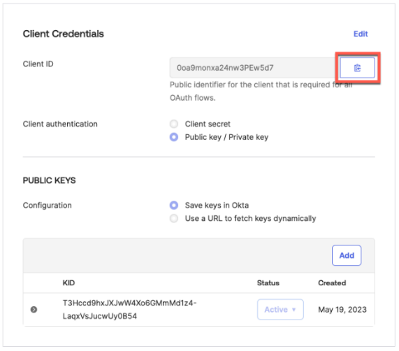
Scroll down until you see General Settings section, click Edit and uncheck “Require Demonstrating Proof of Possession (DPoP) header in token requests.”
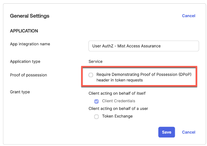
Step 3—Configure App API Scopes
Go to the Okta API Scopes tab and grant the following API permissions.
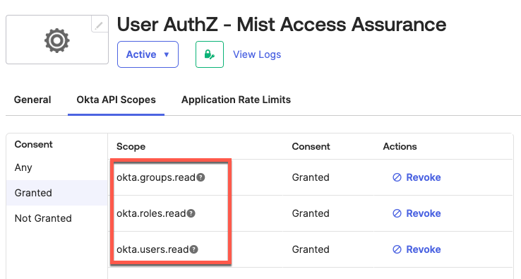
Step 4 – Assign Admin Role to App
Navigate to Admin roles tab and assign Read-only Administrator role, otherwise app will not be able to read any data via API.
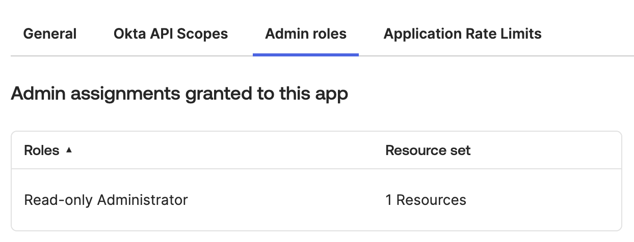
Okta Integration Part 4: Local Okta User Creation Example
Local Okta Users creation is optional! You may use other methods to manage your User Accounts.
To add a new User Account got to Directory > People > Add person.
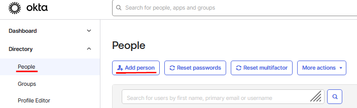
Configure the following example user, then save the account:
- User type=
User - First name=
Joe - Last name=
Doe - Username=user04@example.net (used for IdP login)
- Password
- Password=
<your password> - User must change password on first
login=
Unchecked/Disabled
- Password=
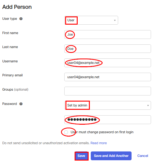
Then Activate the User Account
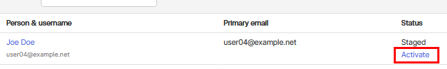
Assign the second Application to this User Account (above we use the name “User AuthZ – Mist Access Assurance”) to allow the readout of the group assigns for this account as part of the IdP.
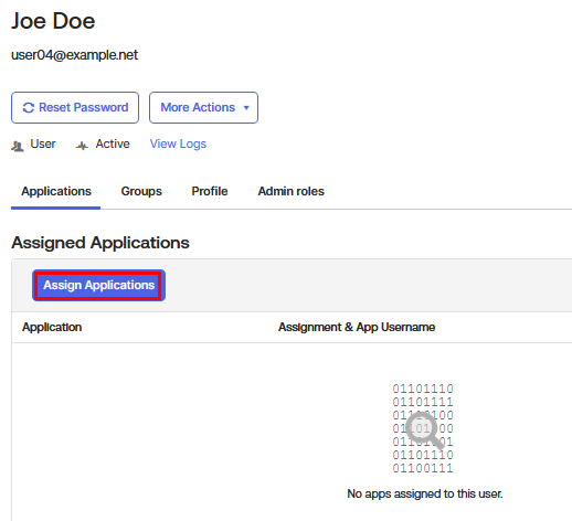
Assign the second Application.
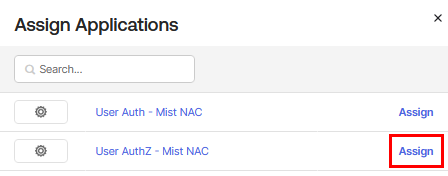
Check the Application is now assigned to the User Account.
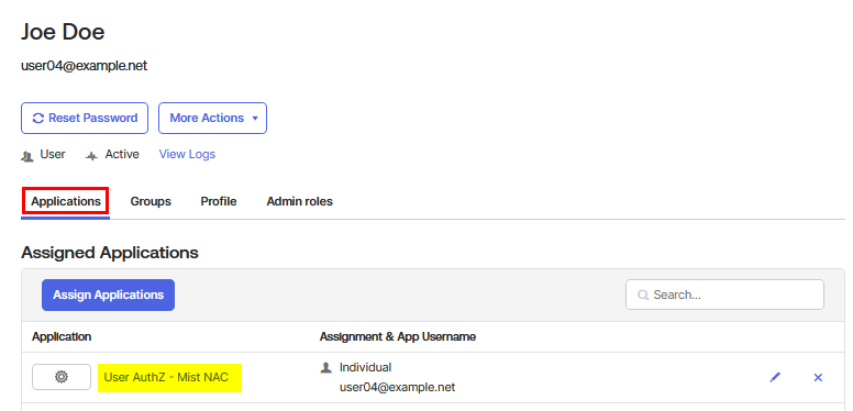
Check the Groups this User Account belongs to.
The group Everyone is default. You can add more as
required. All these groups will then be reported back to the Mist
Authentication Cloud and one can make Label based decisions.
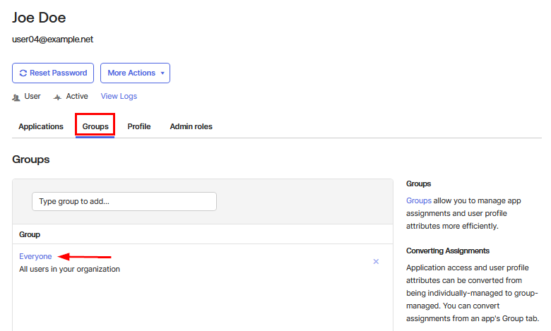
Okta Integration Part 5: Juniper Mist Cloud Configuration
First, get your Okta tenant ID into the new IdP under the Juniper Mist dashboard.
Step 1—Add Identity Provider
In the Juniper Mist dashboard, navigate to Organization > Access > Identity Providers > Add.
Configure the IdP as follows:
- IDP Type=
OAuth - OAuth Type=
Okta - OAuth Tenant ID=
<Okta Tenant ID (from Part
1)>
Should you use an Okta developer account for testing then the OAuth Tenant ID must not contain a domain extension and look like “dev-<number>.”
- Domain Names=
<Your Okta users domain name(s), e.g.
company.com>
- OAuth CC Client ID=
<Client ID you copied in Part 3 /
Step 2>
- OAuth CC Private Key=
<Private key you copied Part 3 /
Step 2>
- OAuth ROPC Client ID=
<Client ID from Part 2 / Step 3
of this guide>
- OAuth ROPC Client Secret=
<Secret from Part 2 / Step 3
of this guide>
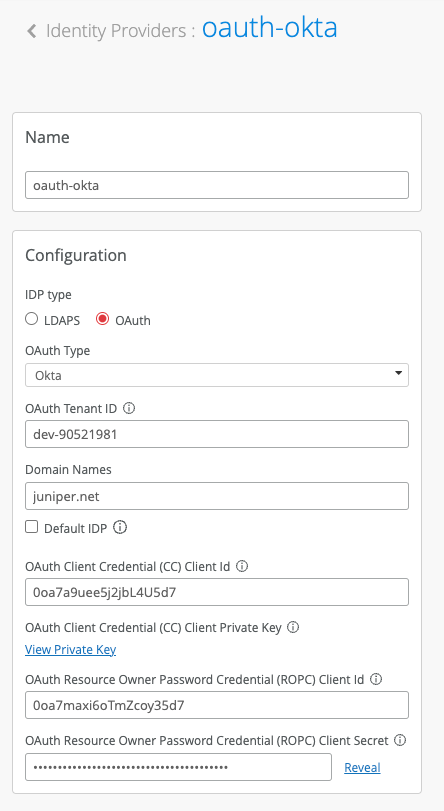
Validation
In the case of a successful EAP-TLS client authentication with a subsequent IdP lookup against Okta, you should see a NAC Group Lookup Success event with IdP roles fetched from Okta.
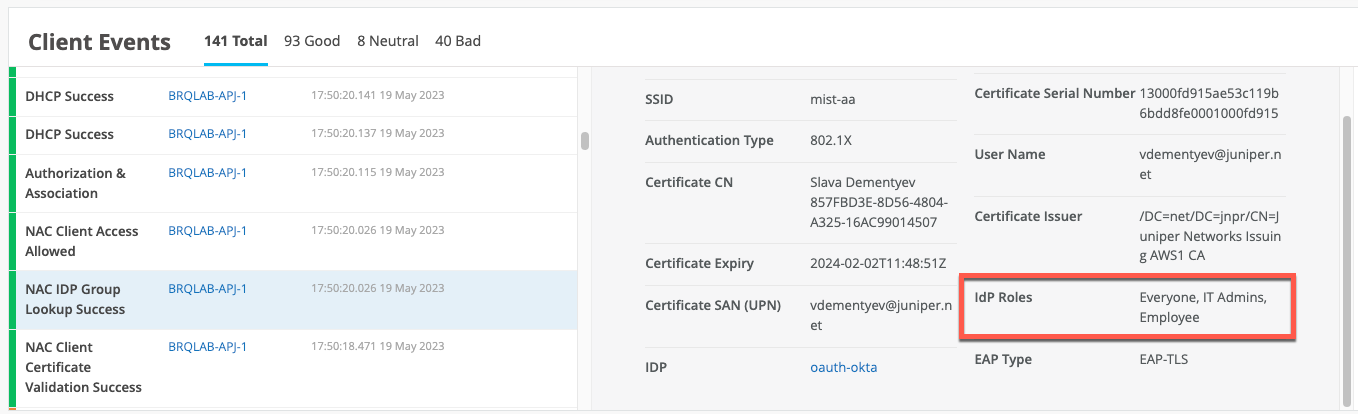
In the case of a successful EAP-TTLS authentication, you would also see a successful NAC IDP Authentication Success event indicating that Okta has verified the user credentials.
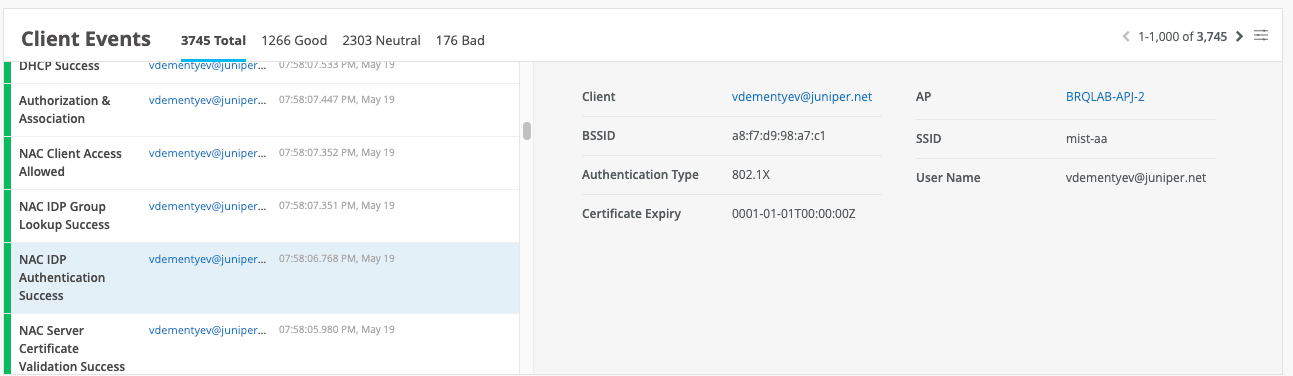
Own LDAP Directory
The steps below are provided to give you an idea about the steps taken when you want to test against a simple minimalistic LDAP repository. The LDAP repository and its directory structure were kept as basic as possible. We suggest that you not put it into production, but it might help to understand the processes if you intend to create a similar integration.
The information presented in this chapter is limited to lab usage only and not meant to be used in production.
Own LDAP Directory Part 1: Create an Instance with a Public IP Address
The first step is to set up an instance running somewhere that can host the LDAP software. This can be a container, a virtual machine or a physical server. You do not require much in the way of resources or CPU power. You can even run the service on a Raspberry Pi. An important aspect of this solution is that you need to have a static public IP address and translate the LDAPS TCP port 636 to the private LDAP instance if the instance is not directly connected to the static public IP address.
Remember that the Juniper Mist authentication cloud (located on the Internet) needs to be able to open a connection to the private LDAP instance to check credentials. If you host that instance locally, you likely need to ask your IT team to allow this connection through an enterprise firewall. An alternative is to create an instance in a public cloud provider as you can then more easily get a public IP address mapped to that instance.
Whichever option you choose, note down the public IP address for the LDAP instance for the next process. In our example, we created a small Ubuntu 22.04 VM on a public cloud to run the LDAP instance.
Own LDAP Directory Part 2: Create Certificates for LDAPS
Once the LDAP instance with a static public IP address is in place, you must create a certificate using the customer’s PKI for a TLS server. If you plan to put the service into production later, the best option is to add it to DNS with FQDN. Here, we just use the static IP address for simplicity. The example below uses a home-grown PKI based on OpenSSL, so you likely need to use similar steps that are relevant to the customer’s PKI. Obviously, you need to substitute 127.0.0.1 with your own IP address.
cd examplePKI
openssl genrsa -out ldapserveraz.example.key 4096
openssl req -new -key ldapserveraz.example.key -subj '/C=US/ST=California/L=Sunnyvale/O=Example TEST-Corp./OU=IT-Department/CN=127.0.0.1' -out ldapserveraz.example.csr
cat <<EOF >ca-server.extensions.cnf
basicConstraints=critical,CA:FALSE
keyUsage = digitalSignature,nonRepudiation,keyEncipherment,dataEncipherment,keyAgreement
extendedKeyUsage = serverAuth
subjectAltName=IP:127.0.0.1
subjectKeyIdentifier=hash
authorityKeyIdentifier=keyid,issuer
EOF
openssl ca -config casign.conf -extfile ca-server.extensions.cnf -out ldapserveraz.example.pem -infiles ldapserveraz.example.csr
openssl x509 -in ldapserveraz.example.pem -out strip.pem
cat strip.pem >ldapserveraz.example.pem
cat ldapserveraz.example.pem
-----BEGIN CERTIFICATE-----
.
.
-----END CERTIFICATE-----
cat ldapserveraz.example.key
-----BEGIN RSA PRIVATE KEY-----
.
.
-----END RSA PRIVATE KEY-----
Own LDAP Directory Part 3: Install the LDAP Service
In our example, we used a Docker container inside our VM, so the first step was installing Docker itself:
apt-get install apt-transport-https ca-certificates curl gnupg-agent software-properties-common -y
apt-key adv --keyserver keyserver.ubuntu.com --recv-keys 7EA0A9C3F273FCD8
curl -fsSL https://download.docker.com/linux/ubuntu/gpg | sudo apt-key add -
add-apt-repository "deb [arch=amd64] https://download.docker.com/linux/ubuntu $(lsb_release -cs) stable"
apt-get update
apt-get install docker-ce docker-ce-cli containerd.io docker-compose -y
Then, you can install an OpenLDAP Docker container and configure the certificates for LDAPS:
# create some storage directories
docker rm -f openldap-server
rm -fR /data/slapd/*
mkdir -p /data/slapd/config
mkdir /data/slapd/database
mkdir /data/slapd/certs
chmod 775 -R /data/slapd
chown -R $USER:docker /data/slapd
apt-get install -y ldap-tools
# we use the cacert.pem File of our root-ca
# as our Enterprise root CA
cat <<EOF >/data/slapd/certs/cacert.pem
-----BEGIN CERTIFICATE-----
.
.
-----END CERTIFICATE-----
EOF
cat <<EOF >/data/slapd/certs/ldapserver.example.pem
-----BEGIN CERTIFICATE-----
.
# use the server certificate generated above for the cn=<public-ip>
.
-----END CERTIFICATE-----
EOF
cat <<EOF >/data/slapd/certs/ldapserver.example.key
-----BEGIN RSA PRIVATE KEY-----
.
# use the server key generated above for the cn=<public-ip>
.
-----END RSA PRIVATE KEY-----
EOF
# create and remember a strong ADMIN password
ADMINPASS=`cat /dev/urandom | tr -dc 'a-zA-Z0-9' | fold -w 20 | head -n 1`
echo 'The Admin password is:'$ADMINPASS >ldapadminpass.txt
echo 'The Admin password is:'$ADMINPASS
The Admin password is:MC0xxxxxxxxxxxxxRjQ6IC
# lauch the ldap docker instance
docker rm -f openldap-server
docker run \
  --restart=always \
  --name openldap-server \
  -p 389:389 \
  -p 636:636 \
  --env LDAP_ORGANISATION="example.net" \
  --env LDAP_DOMAIN="ldap.example.net" \
  --env LDAP_BASE_DN="dc=ldap,dc=example,dc=net" \
  --env LDAP_ADMIN_PASSWORD=$ADMINPASS \
  --volume /data/slapd/database:/var/lib/ldap \
  --volume /data/slapd/config:/etc/ldap/slapd.d \
  --volume /data/slapd/certs:/container/service/slapd/assets/certs \
  --env LDAP_READONLY_USER=true \
  --env LDAP_READONLY_USER_USERNAME=readonly \
  --env LDAP_READONLY_USER_PASSWORD=juniper123 \
  --env LDAP_TLS=true \
  --env LDAP_TLS_CRT_FILENAME=ldapserver.example.pem \
  --env LDAP_TLS_KEY_FILENAME=ldapserver.example.key \
  --env LDAP_TLS_CA_CRT_FILENAME=cacert.pem \
  --env LDAP_TLS_VERIFY_CLIENT=try \
  --detach osixia/openldap:latest
#docker rm -f phpldapadmin
#docker run \
    --restart=always \
    --name phpldapadmin \
    -p 80:80 \
    --env PHPLDAPADMIN_LDAP_HOSTS=172.31.0.10 \
    --env PHPLDAPADMIN_HTTPS='false' \
    --detach osixia/phpldapadmin:latest
To test your service installation, you can use the following:
# check if ldap docker works at all (unsecure as readonly user)
ldapsearch \
               -h 127.0.0.1 \
               -p 389 \
               -D 'cn=readonly,dc=ldap,dc=example,dc=net' \
               -w 'juniper123' \
               -b 'dc=ldap,dc=example,dc=net' \
               '(objectClass=*)'
# extended LDIF
#
# LDAPv3
# base <dc=ldap,dc=example,dc=net> with scope subtree
# filter: (objectClass=*)
# requesting: ALL
#
# ldap.example.net
dn: dc=ldap,dc=example,dc=net
objectClass: top
objectClass: dcObject
objectClass: organization
o: example.net
dc: ldap
# search result
search: 2
result: 0 Success
# numResponses: 2
# numEntries: 1
Own LDAP Directory Part 4: Create a Basic LDAP Directory
To create a small LDAP directory for testing, we imported a small one that was created elsewhere as an LDIF file.
# create a small ldif file for import
cat <<EOF >import.ldif
# LDIF Export for dc=ldap,dc=example,dc=net
# Server: 192.168.10.14 (192.168.10.14)
# Search Scope: sub
# Search Filter: (objectClass=*)
# Total Entries: 8
#
# Generated by phpLDAPadmin (http://phpldapadmin.sourceforge.net) on June 23, 2023 2:55 pm
# Version: 1.2.5
version: 1
# Entry 1: dc=ldap,dc=example,dc=net
#dn: dc=ldap,dc=example,dc=net
#dc: ldap
#o: example.net
#objectclass: top
#objectclass: dcObject
#objectclass: organization
# Entry 2: ou=groups,dc=ldap,dc=example,dc=net
dn: ou=groups,dc=ldap,dc=example,dc=net
objectclass: organizationalUnit
objectclass: top
ou: groups
# Entry 3: cn=employees,ou=groups,dc=ldap,dc=example,dc=net
dn: cn=employees,ou=groups,dc=ldap,dc=example,dc=net
cn: employees
gidnumber: 501
memberuid: user01
memberuid: user02
memberuid: user03
objectclass: posixGroup
objectclass: top
# Entry 4: cn=employer,ou=groups,dc=ldap,dc=example,dc=net
dn: cn=employer,ou=groups,dc=ldap,dc=example,dc=net
cn: employer
gidnumber: 500
objectclass: posixGroup
objectclass: top
# Entry 5: ou=users,dc=ldap,dc=example,dc=net
dn: ou=users,dc=ldap,dc=example,dc=net
objectclass: organizationalUnit
objectclass: top
ou: users
# Entry 6: cn=user01,ou=users,dc=ldap,dc=example,dc=net
dn: cn=user01,ou=users,dc=ldap,dc=example,dc=net
cn: user01
gidnumber: 501
homedirectory: /home/users/user01
loginshell: /bin/bash
mail: user01@example.net
objectclass: inetOrgPerson
objectclass: posixAccount
objectclass: top
sn: user01
uid: user01
uidnumber: 1000
userpassword: juniper123
# Entry 7: cn=user02,ou=users,dc=ldap,dc=example,dc=net
dn: cn=user02,ou=users,dc=ldap,dc=example,dc=net
cn: user02
gidnumber: 501
homedirectory: /home/users/user02
loginshell: /bin/bash
mail: user02@example.net
objectclass: inetOrgPerson
objectclass: posixAccount
objectclass: top
sn: user02
uid: user02
uidnumber: 1001
userpassword: juniper123
# Entry 8: cn=user03,ou=users,dc=ldap,dc=example,dc=net
dn: cn=user03,ou=users,dc=ldap,dc=example,dc=net
cn: user03
gidnumber: 501
homedirectory: /home/users/user03
mail: user03@example.net
objectclass: inetOrgPerson
objectclass: posixAccount
objectclass: top
sn: user03
uid: user03
uidnumber: 1002
userpassword: juniper123
EOF
# import your LDIF file to create the accounts
ldapadd \
               -h 127.0.0.1 \
               -p 389 \
               -D 'cn=admin,dc=ldap,dc=example,dc=net' \
               -w $ADMINPASS \
               -f import.ldif
adding new entry "ou=groups,dc=ldap,dc=example,dc=net"
adding new entry "cn=employees,ou=groups,dc=ldap,dc=example,dc=net"
adding new entry "cn=employer,ou=groups,dc=ldap,dc=example,dc=net"
adding new entry "ou=users,dc=ldap,dc=example,dc=net"
adding new entry "cn=user01,ou=users,dc=ldap,dc=example,dc=net"
adding new entry "cn=user02,ou=users,dc=ldap,dc=example,dc=net"
adding new entry "cn=user03,ou=users,dc=ldap,dc=example,dc=net"
Own LDAP Directory Part 5: Juniper Mist Cloud Configuration
Navigate to Organization > Identity Providers.
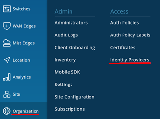
Add a new IdP with the following configuration:
- Name=
ownLDAP - IDP Type=
LDAPS - LDAP Type=
Custom - Group Filter=
memberOf - Member Filter=
memberOf - User Filter=
(mail=%s)(you may also use(uid=%s)but then the TTLS client must only use their name and not their email address when authenticating) - Server Hosts=
<DNS-FQDN OR Public-IP>(Note that you MUST have a matching server certificate on the LDAPS server where the common name matches what you configure here) - Domain Names=
example.net - Bind DN=
cn=readonly,dc=ldap,dc=example,dc=net - Bind Password=
juniper123 - Base DN=
ou=users,dc=ldap,dc=example,dc=net
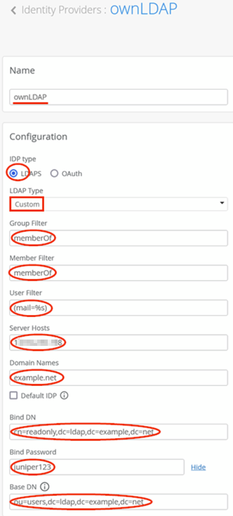
In our case, the certificate for the LDAPS connection was made from the same customer PKI. Hence, no additional steps are required. Should it be from an external LDAPS service provider, you need to obtain and add a client certificate. See the next figure:
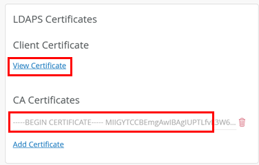
To test the IdP integration under Organization > Auth Policies, create a simple EAP-TTLS rule like that shown below:
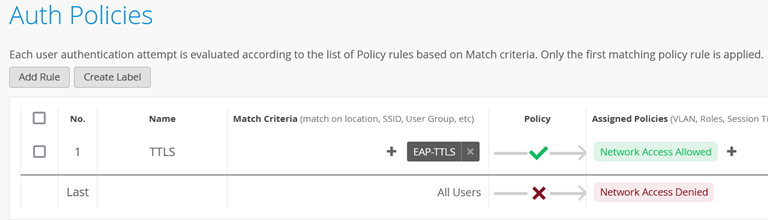
In our directory, the EAP supplicant can then use the 3
usernames (
user01@example.net
,
user01@example.net
,
and
user03@example.net
)
with the password juniper123 for all 3 usernames (or
you can change this in the LDIF file before importing).
When going through the authentication process, you should see the following events.