Fast Track to Rack Installation and Power
This procedure guides you through the simplest steps for the most common installation to mount your EX4100-H switch and connect it to power. Have more complex installation needs? See Install the EX4100-H Switch
Mount an EX4100-H-12MP Switch in a Desktop Orientation or Flat Surface Within a Cabinet
Desktop mounting is the default mounting option for the EX4100-H-12MP switch. For the rest of the mounting options, refer Install the EX4100-H Switch.
The EX4100-H switch (with PSU if using external PSU or with PSU FRU) must be installed in a certified cabinet or enclosure to prevent any personal injury due to access to live parts. The enclosure shall be accessible by using a tool. The access to the switch shall be restricted. Only instructed and skilled person must access the switch. This requirement applies to any off-the-shelf external PSU as well.
For traffic control application (NEMA TS2), the EX4100-H switch must be installed in a NEMA 4 certified cabinet or certified enclosure as per NEMA TS2 standard ( section 7 requirement). The cabinet shall meet the NEMA TS2 section 7 requirement.
EX4100-H with all types of mounting (wall, desk, magnet, rack, and Din) must be installed in a certified cabinet.
The certified cabinet or enclosure must meet the fire enclosure requirements of UL, EN 62368-1 to ensure no foreign objects fall into the switch (and PSU if using external PSU) and no flaming particles fall out from the switch (and PSU if using external PSU) to outside.
User shall assess the climatic/environmental conditions at installation site to select the certified cabinet/enclosure to ensure that the switch (and PSU if using external PSU) is protected from dust, rain, salt fog, pollutants to prevent any damage. Below are few examples.
For indoor and indoor non office installation with very low dust/moisture – cabinet/enclosure must be certified to minimum IP 54 (defined in EN60529) or certified TYPE 4 (defined in UL 50).
For installing the switch (and PSU if using external PSU) in outdoor environment (to protect from dust, corrosion, moisture, salt fog, pollutants, rain) enclosure or certified cabinet must be certified to IP65 or higher (IP code defined in EN 60529) or TYPE 4 (defined in UL 50E, UL50).
When using the DDR-120B-12 external PSU with the EX4100-H-12MP switch, ensure to connect the input of this PSU to a DC power source that is isolated from the mains.
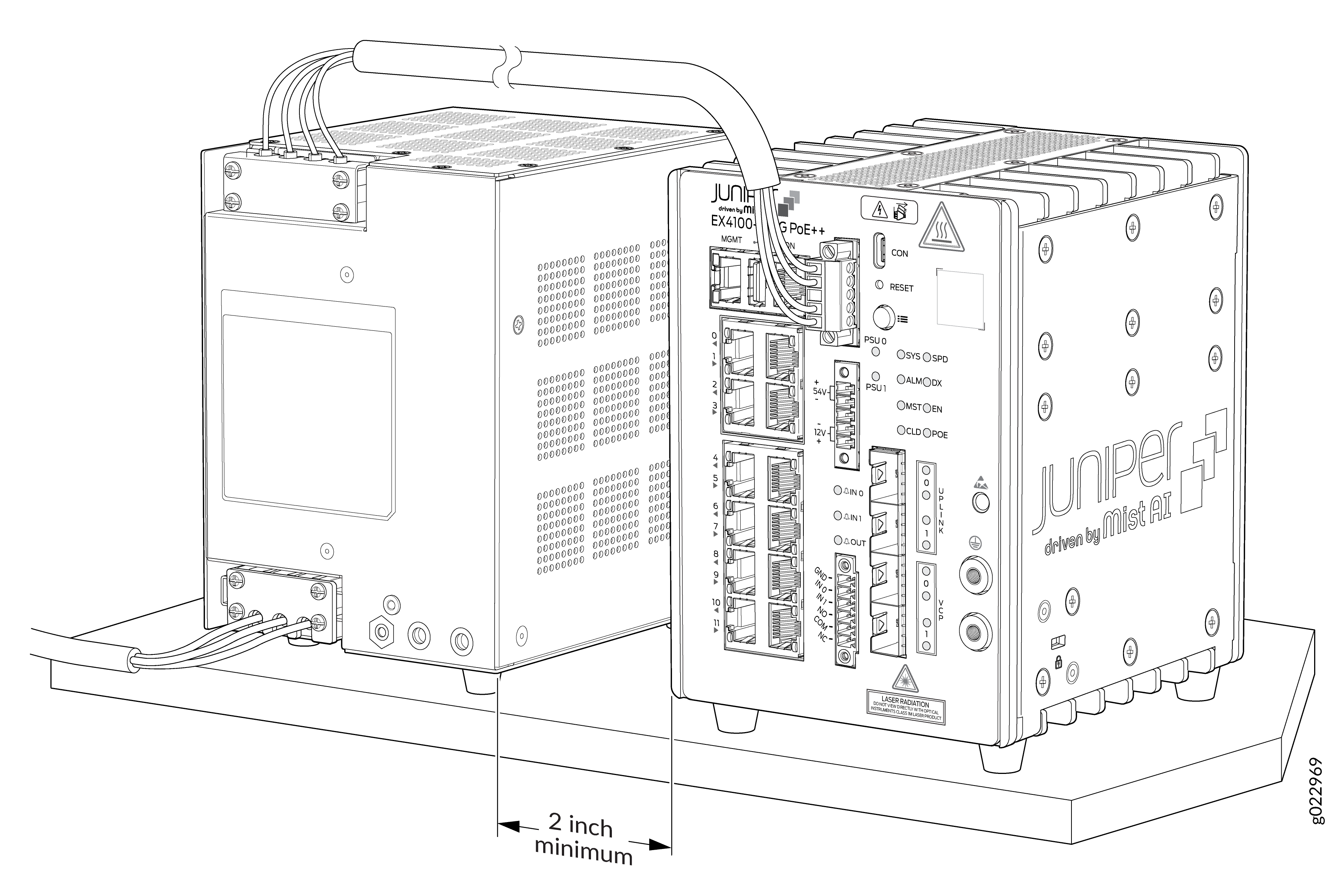
You can mount the EX4100-H-12MP switch and the external PSU on a desk or any other level surface within a certified cabinet. The surface should be flat or level and not be an inclined surface or area. Note that you can connect the EX4100-H-12MP switch to any one of the following:
-
One external AC PSU
-
One external DC PSU
-
Two external AC PSUs
-
Two external DC PSUs
-
One external AC PSU and one external DC PSU
Allow sufficient space of 1 RU above and 1 RU below the switch for cooling. Insufficient space can lead to overheating of the switch.
-
Connect to power. See Connect the EX4100-H-12MP to Power
Mount an EX4100-H-24MP or EX4100-H-24F Switch in a Rack Within a Cabinet
Two-post rack mounting is the default mounting option for the EX4100-H-24MP or EX4100-H-24F switch. For the rest of the mounting options, refer Install the EX4100-H Switch.
Allow sufficient space of 1 RU above the switch and 1 RU below the switch when mounted in rack. Insufficient space can lead to overheating of the switch.
-
Verify that the site meets the requirements described in Environmental Requirements and Specifications
-
Place the rack in its permanent location, allowing adequate clearance for airflow and maintenance, and secure it to the building structure.
-
Read General Safety Guidelines and Warnings, with particular attention to Chassis and Component Lifting Guidelines.
Ensure that you have the following parts and tools available:
-
Phillips (+) screwdriver, number 2 (not provided).
-
Screws to secure the switch to the rack (not provided).
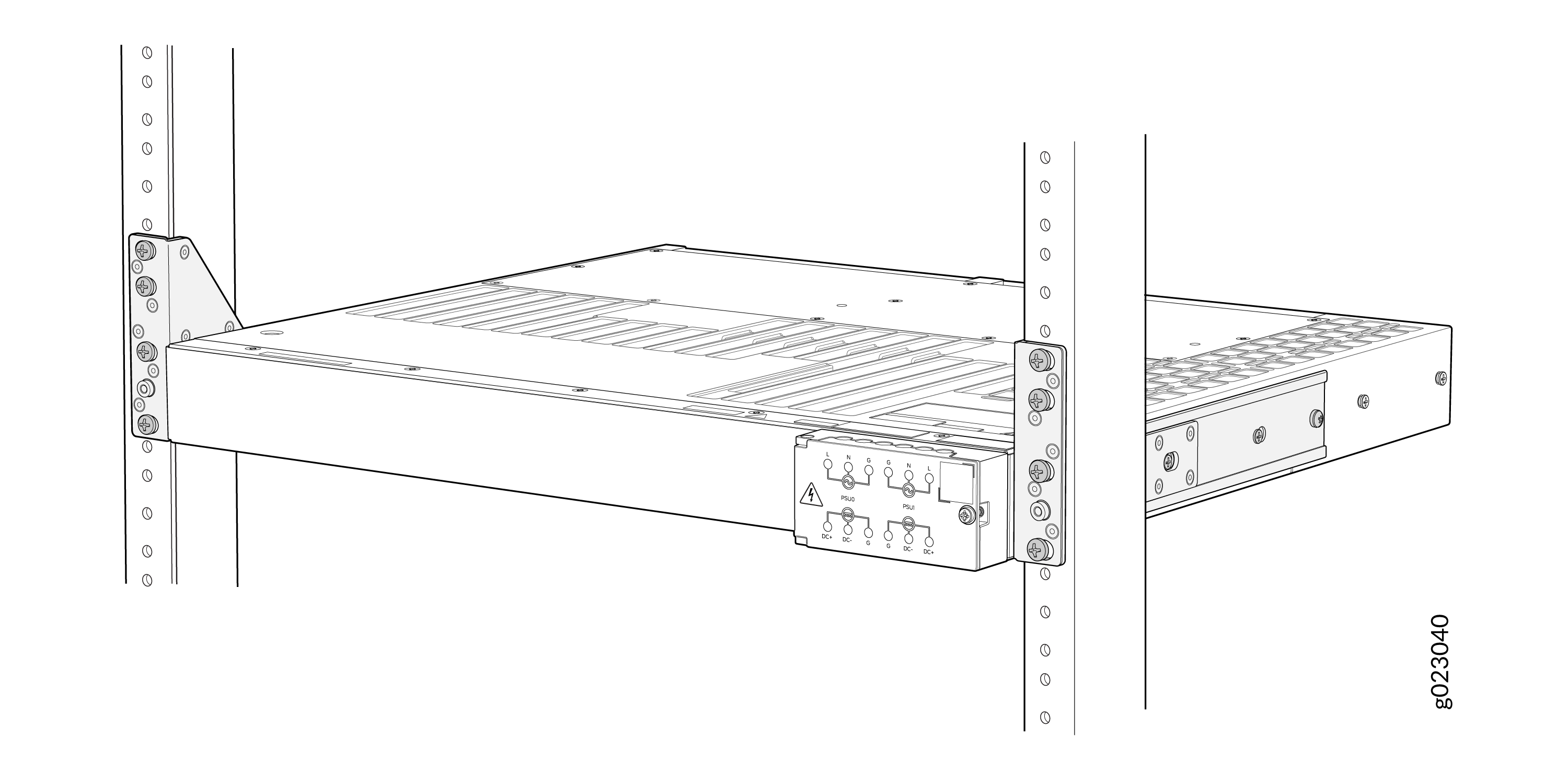
You can mount the switch on two posts of a 19-in. rack or cabinet by using the front mounting brackets provided with the switch. (The remainder of this topic uses rack to mean rack or cabinet.)
One person must be available to lift the switch while another secures the switch to the rack.
If you are mounting multiple units on a rack, mount the heaviest unit at the bottom of the rack and mount the other units from the bottom of the rack to the top in decreasing order of the weight of the units.
-
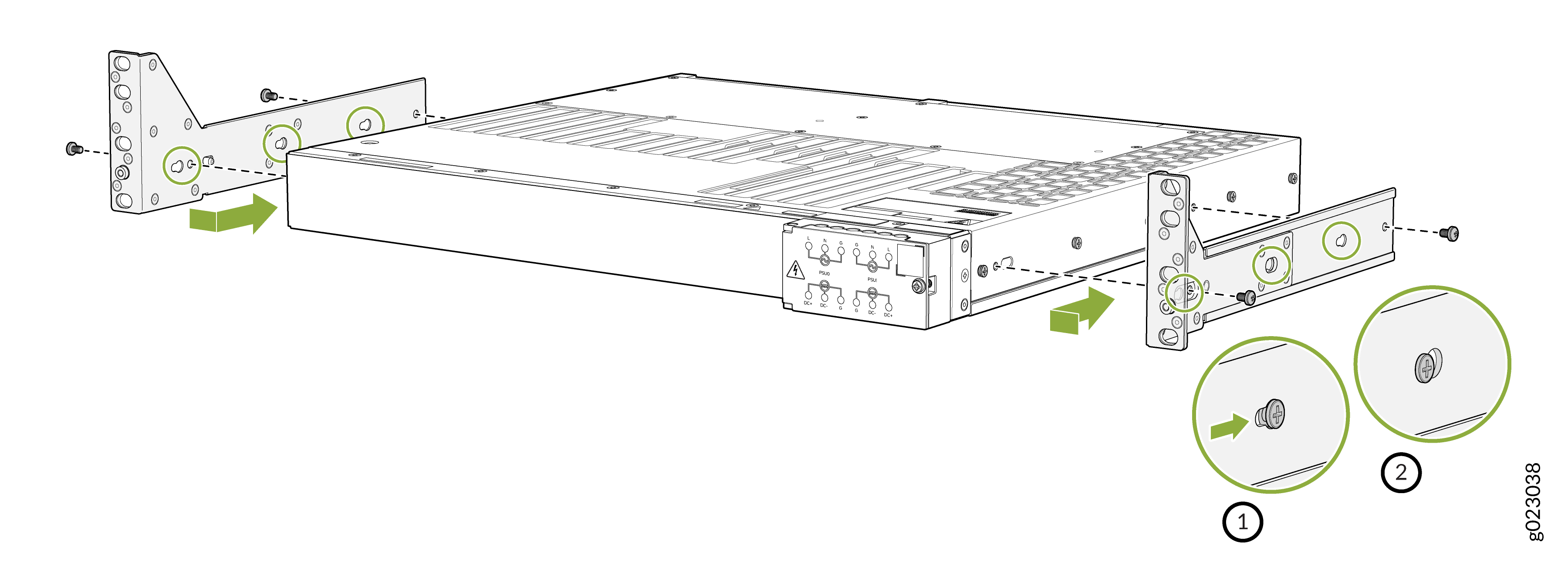
Insert the M4 x 6mm Phillips screws to attach the mounting bracket into the
aligned holes on the switch chassis and tighten the screws.
Note:
Recommended torque is 10 +/- 0.5 Lb.in
-
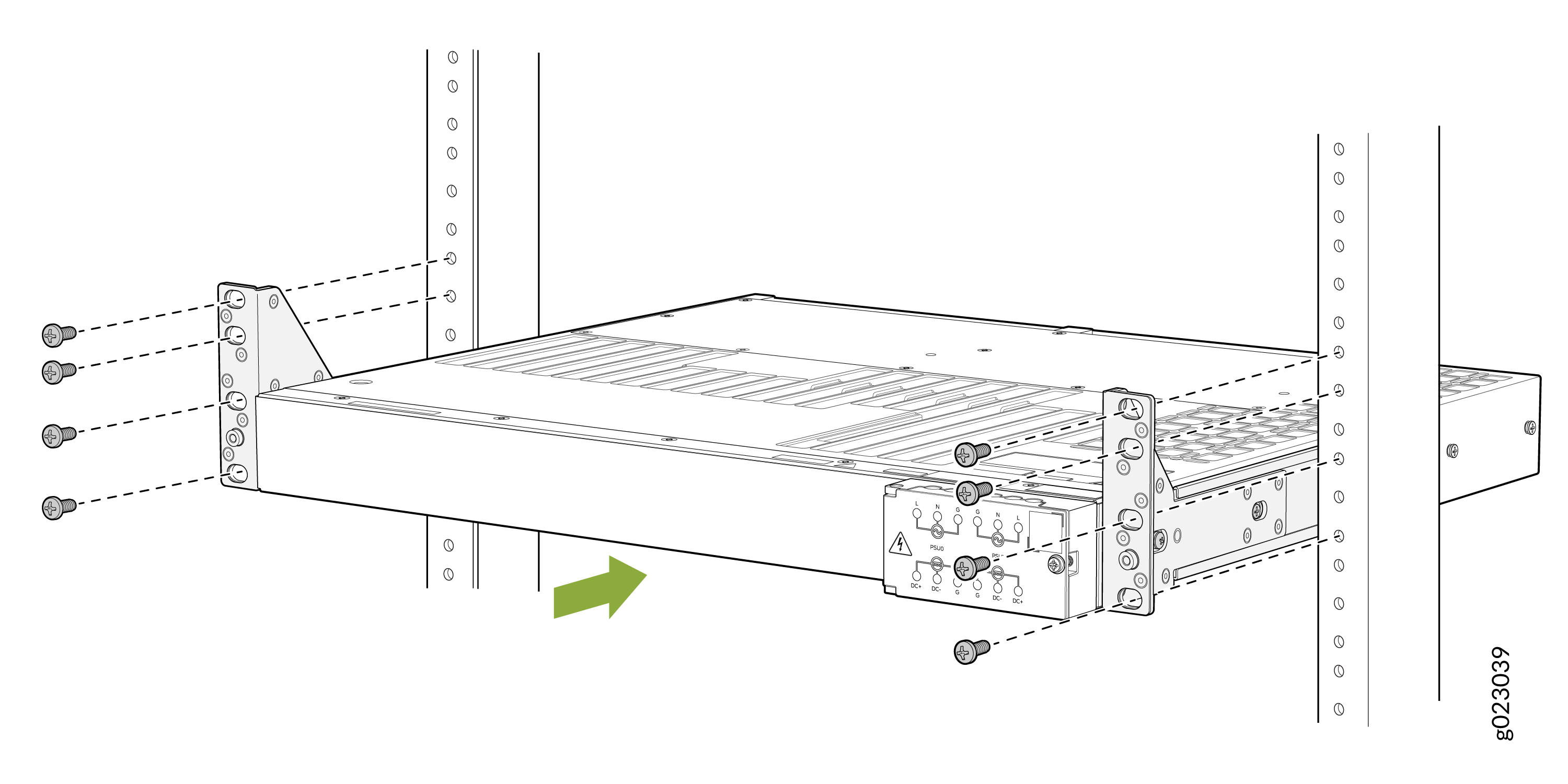
To attach the switch to the rack, lift the switch, and position it in the
rack, aligning the holes of the mounting brackets with the threaded holes in
the posts of the rack. Align the holes in each mounting bracket with a hole
in each rack rail, making sure that the switch chassis is level.
-
Have a second person secure the switch to the rack and tighten the
screws.
Connect the EX4100-H-12MP to Power
To connect the EX4100-H-12MP switch to AC and/or DC power, perform the following tasks:
To ensure proper operation and to meet safety and electromagnetic interference (EMI) requirements, you must connect the EX4100-H switch to earth ground and the external PSUs (for EX4100-H-12MP) to earth ground before you connect power to the switch.
EX4100-H-12MP switches and their external PSUs have a two-hole protective grounding terminal. We recommend that you use the switch chassis protective grounding terminal as the only method for grounding the switch chassis regardless of the power supply configuration. However, if additional grounding methods are available, you can also use those methods additionally. For example, on the PSU, you can connect the PE (grounding symbol) mark terminal of the terminal block to the input grounding wire in the power cord of the input power cable. This switch was tested to meet or exceed all applicable EMC regulatory requirements with the switch chassis protective grounding terminal connected correctly.
- Ground the EX4100-H-12MP Switch and the External PSU
- Connect the Input Power Cable and Power On the Switch
Ground the EX4100-H-12MP Switch and the External PSU
To ground the EX4100-H-12MP switch and the external PSU, perform the following steps:
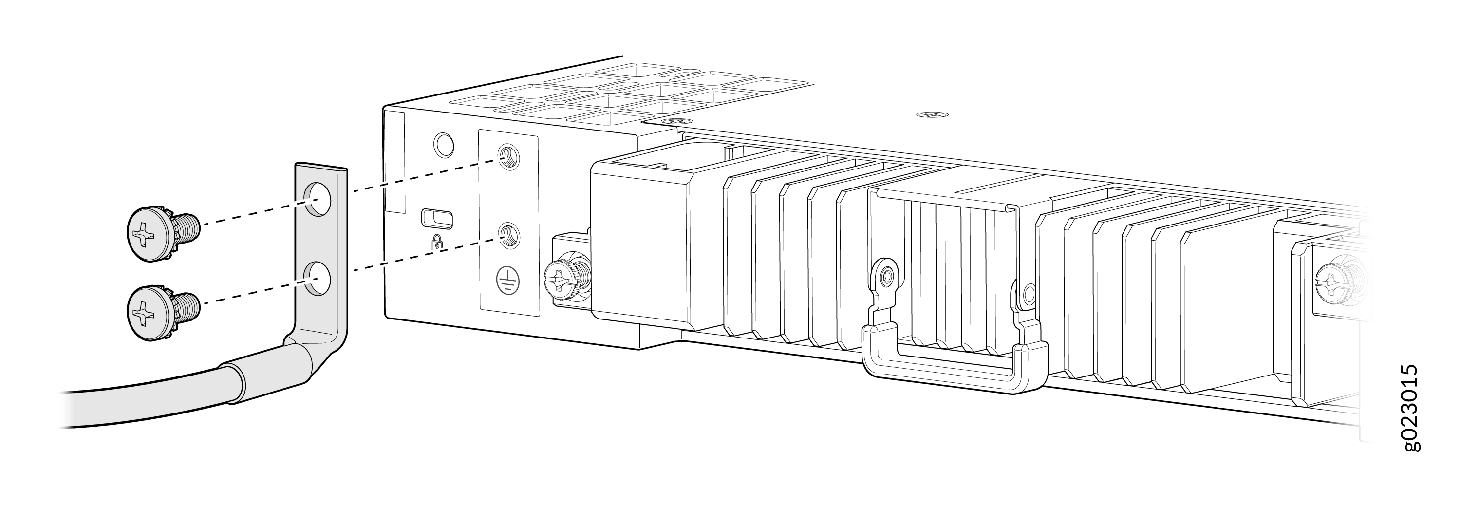
To ground the switch, connect one end of the grounding cable to a proper earth ground, such as the cabinet in which the switch is mounted.
Place the grounding lug attached to the grounding cable over the protective earthing terminal on the front panel.

Secure the grounding lug to the protective earthing terminal with the screws. Ensure that the grounding cable does not touch or block access to other switch components.
To ground the PSU, connect one end of the grounding cable to a proper earth ground, such as the cabinet in which the PSU is mounted.
Place the grounding lug attached to the grounding cable over the protective earthing terminal on the front panel of the PSU.

Secure the grounding lug to the protective earthing terminal of the PSU with the screws. Ensure the grounding cable does not touch or block access to other PSU components.
Connect the Input Power Cable and Power On the Switch
For information about the supported AC power cord specifications, see Table 9.
-
You must keep the power source switched off before starting this procedure and switch it on only after completing this procedure.
-
Only skilled persons shall be allowed to connect or do the wiring of PSU to Mains.
-
PSU output connections to switch and PSU inlet connections should not be done when the AC/DC power cord is connected to the main source.
-
Connect the AC PSU to AC mains through a 2-hole circuit breaker rated at 16 A or as per local code.
To connect the input power cable:
Remove the protective terminal cover from the PSU input power terminal.
Note:An initial batch of PSUs were shipped with torx screws (hexagonal shaped screws) for the protective terminal covers (input and output) of the PSU. If using a PSU with this type of screw; to install or remove the protective terminal covers from the PSU you use screwdriver type Torx 10 with torque 3.5 lb.in

Insert the power cord wires of the power source into the power terminal inputs of the PSU. You can connect the EX4100-H-12MP switch to any one of the following:
One external AC PSU
One external DC PSU
Two external AC PSUs
Two external DC PSUs
One external AC PSU and one external DC PSU
On an AC PSU input, the power terminals are marked as L, N, PE (grounding symbol). On a DC PSU input, the power terminals are marked as +, -, and PE (grounding symbol). Always insert the grounding wire or protective earth (PE) power cord wire into the PE input power terminal first. For an AC PSU, insert the line, single phase (L) power cord wire and neutral (N) power cord wire into the L and N input power terminals respectively. For a DC PSU, insert + power cord wire and - power cord wire into the + and - input power terminals respectively.
Note: Use Phillips #2 screwdriver with torque 6 lb.in
Secure the protective terminal cover with the screws over the PSU input power terminal.

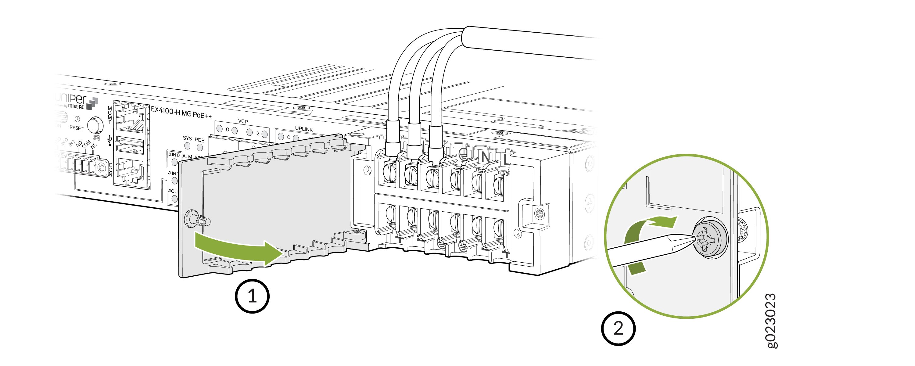
Remove or loosen the protective terminal cover of the PSU output power terminal. It is not required to remove the protective terminal cover; you can loosen the protective terminal cover until you can see the PSU output power terminals.

From the PSU output terminal, connect the PSU to the EX4100-H-12MP switch using the interconnecting wire. Secure the y-shaped connection points of the interconnecting wire onto the PSU output power terminal. If required, modify the strength of the physical connection by tightening or loosening the screws on the PSU output power terminal.
Note: Use Phillips #2 screwdriver with torque 6 lb.inThe PSU output terminal has two voltages - 54V and 12V. Connect the Y-shared connection points of the interconnecting wire in this manner (refer the image below):
54v +– Connect the y-shaped connection point of the red interconnecting wire.
54v -– Connect the y-shaped connection point of the black interconnecting wire.
12v+– Connect the y-shaped connection point of the brown interconnecting wire.
12v-– Connect the y-shaped connection point of the gray interconnecting wire.
Connect the other end of the interconnecting wire to the PSU connector on the switch. Assuming you are using only one PSU, connect the other end of the interconnecting wire to the connector for PSU 0 or to the connector for PSU 1, but not to both. A PSU connector is used for connecting only one PSU to the switch.Two PSU connectors are used for connecting two PSUs to the switch. Note that you can connect up to two PSUs to the switch - two AC PSUs, two DC PSUs, one AC PSU and one DC PSU, only one AC PSU, or only one DC PSU.
Connect the other ends of the interconnecting wire to the PSU connector by initially partially loosening the screws on the sides of the PSU connector using slotted/flat head 2.5 mm screwdriver with torque 1.77 lb.in. Then insert the other ends of the interconnecting wire into the PSU connector slots before fastening the screws on the sides of the PSU connector to secure the interconnecting wire to the PSU connector and complete the PSU to switch connection.
Note: To remove or install the PSU connector you use slotted/flat head 3.5mm screwdriver with torque 2.65 lb.in.The other ends of the interconnecting wire to the PSU connector has to be connected in this manner assuming you are using only one PSU:
Connect the interconnecting wire connected to the 54v+ PSU output terminal to the 54v+ PSU connector input of PSU 0 or PSU 1.
Connect the interconnecting wire connected to the 54v- PSU output terminal to the 54v- PSU connector input of PSU 0 or PSU 1.
Connect the interconnecting wire connected to the 12v+ PSU output terminal to the 12v+ PSU connector input of PSU 0 or PSU 1.
Connect the interconnecting wire connected to the 12v- PSU output terminal to the 12v- PSU connector input of PSU 0 or PSU 1.

Secure the protective terminal cover with the screws over the PSU output power terminal.

Connect the EX4100-H-24MP or EX4100-H-24F Switch to Power
To connect the EX4100-H-24MP or EX4100-H-24F switch to power, perform the following tasks:
To ensure proper operation and to meet safety and electromagnetic interference (EMI) requirements, you must connect the EX4100-H switch to earth ground before you connect power to the switch.
EX4100-H switches have a two-hole protective grounding terminal. We recommend that you use the switch chassis protective grounding terminal as the only method for grounding the switch chassis regardless of the power supply configuration. However, if additional grounding methods are available, you can also use those methods additionally. For example, the grounding connection of the AC or DC power cord provides additional grounding. This switch was tested to meet or exceed all applicable EMC regulatory requirements with the switch chassis protective grounding terminal connected correctly.
- Ground the EX4100-H-24MP or EX4100-H-24F Switch
- Connect Power to the EX4100-H-24MP or EX4100-H-24F Switch
Ground the EX4100-H-24MP or EX4100-H-24F Switch
To ground the EX4100-H-24MP or EX4100-H-24F Switch perform the following steps:
To ground the switch, connect one end of the grounding cable to a proper earth ground, such as the cabinet in which the switch is mounted.
Place the grounding lug attached to the grounding cable over the protective earthing terminal on the rear panel.
Secure the grounding lug to the protective earthing terminal with the screws. Ensure that the grounding cable does not touch or block access to other switch components.
Connect Power to the EX4100-H-24MP or EX4100-H-24F Switch
For information about the supported AC power cord specifications, see Table 9.
-
You must keep the power source switched off before starting this procedure and switch it on only after completing this procedure.
-
Only skilled persons shall be allowed to connect or do the wiring of PSU to Mains.
-
When connecting the EX4100-H-24F switch to the AC power source, you must provide an external circuit breaker (2-pole circuit breaker or 4-pole circuit breaker based on your switch) rated minimum 20 A in the building installation.
-
When connecting the EX4100-H-24F switch to the DC power source, we recommend that you use a customer-site 2-pole circuit breaker rated for 25A 80 VDC, or as required by local electrical code.
To connect power to the switch:
Loosen the screw of the power terminal door and open the power terminal door.
Note:Recommended torque is 4.5 +/- 0.5 Lb.in. Recommended screwdriver is Phillips #2 screwdriver.
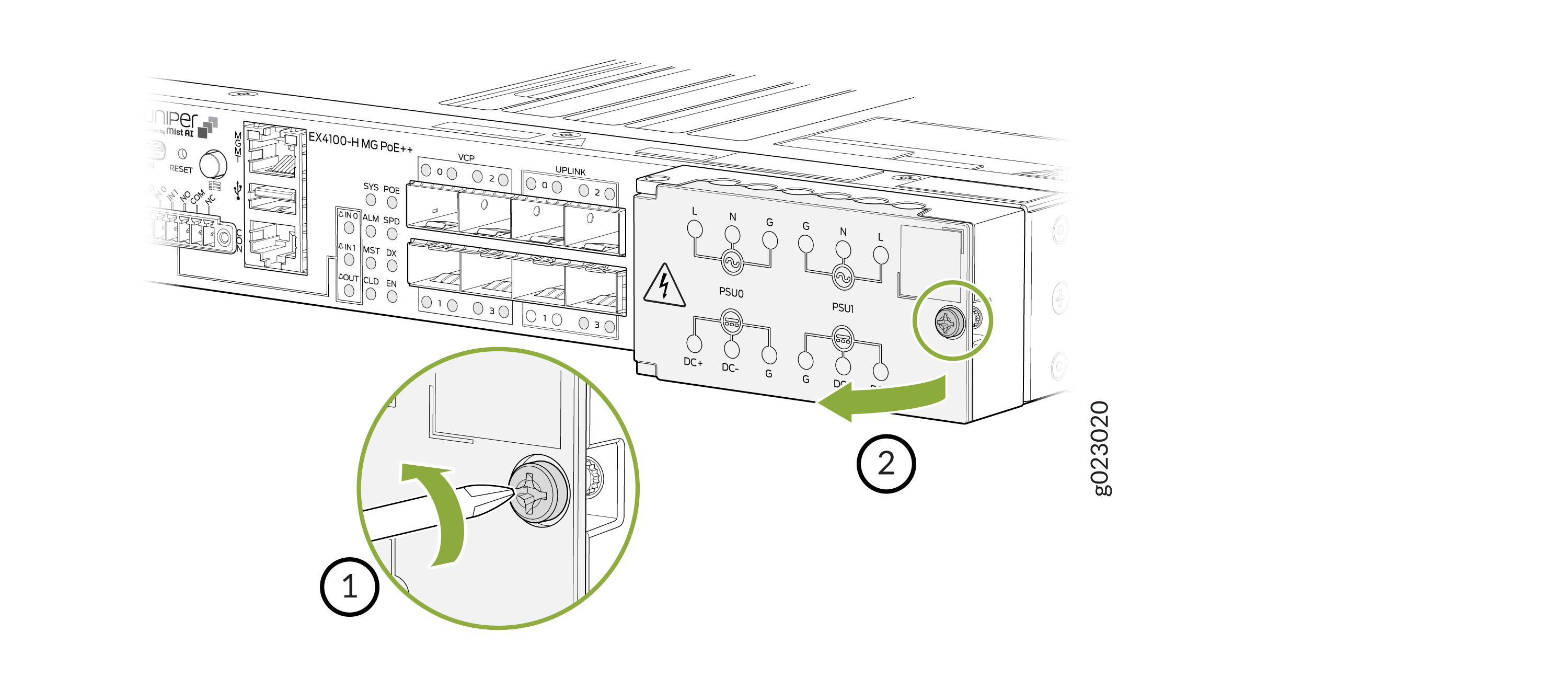
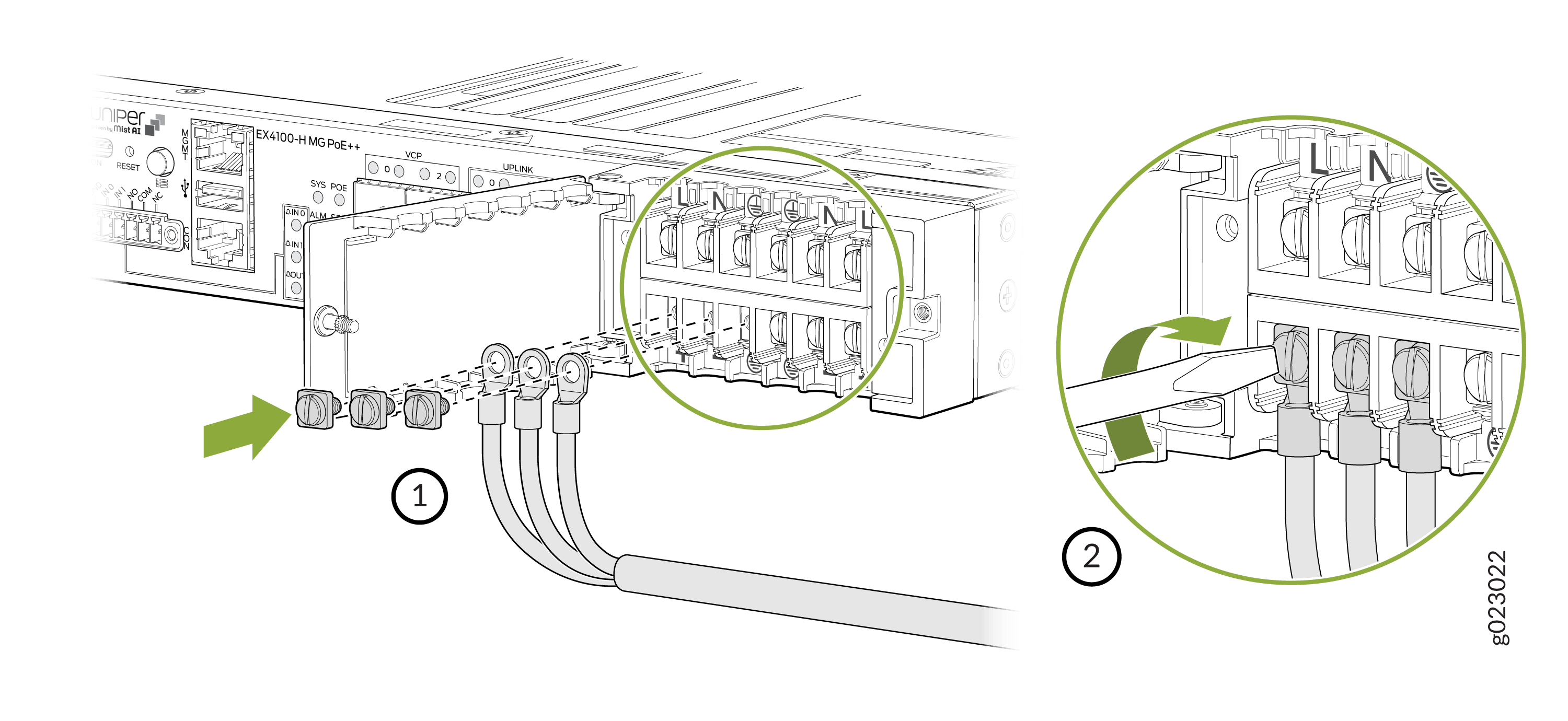
On the rear of the switch, the first slot to insert the PSU is identified as the 0th slot and the second slot to insert the PSU is identified as the 1st slot. After insertion of the PSUs into these slots, their corresponding connections are made from the power input terminals on the front of the switch labeled PSU 0 and PSU 1.
If an AC PSU is inserted into the 0th PSU slot at the rear of the switch, then on the front of the switch, connect the L, N, and G terminals of the section labeled as PSU 0 of the power input terminal, to the AC power source.
If an AC PSU is inserted into the 1st PSU slot at the rear of the switch, then on the front of the switch, connect the L, N, and G terminals of the section labeled as PSU 1 of the power input terminal, to the AC power source.
If a DC PSU is inserted into the 0th PSU slot at the rear of the switch, then on the front of the switch, connect the DC+, DC-, and G terminals of the section labeled as PSU 0 of the power input terminal, to the DC power source.
If a DC PSU is inserted into the 1st PSU slot at the rear of the switch, then on the front of the switch, connect the DC+, DC-, and G terminals of the section labeled as PSU 1 of the power input terminal, to the DC power source.
Note: You can insert PSUs into the rear of the switch in this configuration:One AC PSU
One DC PSU
Two AC PSUs
Two DC PSUs
One AC and one DC PSU
Assuming you have inserted at least one AC PSU into the switch at the rear; to connect the AC PSU to the main power source, loosen the screws marked under the labels L, N, and G and insert the wires of the AC power cord into the slots behind the screws. Tighten the screws and secure the connections. Note that during this procedure, to not plug in the AC power cord into an AC power source, but to do it only after securing the connections and securing the terminal door.
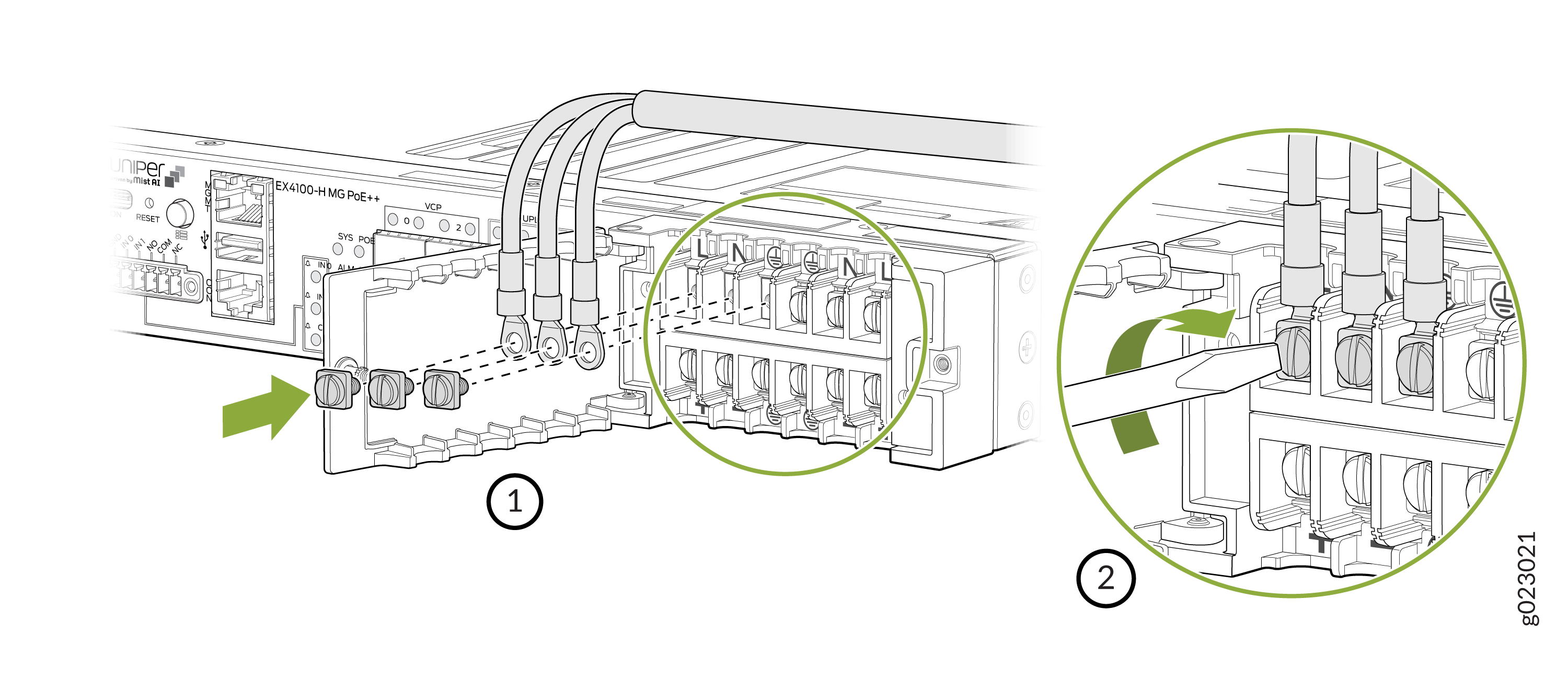
Assuming you have inserted at least one DC PSU into the switch at the rear; to connect the DC PSU to the main power source, loosen the screws marked under the labels DC+, DC-, and G and insert the wires of the DC power cord into the slots behind the screws. Tighten the screws and secure the connections. Note that during this procedure, to not plug in the DC power cord into a DC power source, but to do it only after securing the connections and securing the terminal door.
Note:Recommended torque is 7 +/- 0.5 Lb.in. Recommended screwdriver type is Phillips #2 or slotted/flat head 6 mm.
Shut the terminal door and tighten the screw of the terminal door.
Note:Recommended torque is 4.5 +/- 0.5 Lb.in. Recommended screwdriver is Phillips #2 screwdriver.