- play_arrow Fast Track: Initial Installation
- play_arrow Overview
- play_arrow Site Planning, Preparation, and Specifications
- play_arrow Maintaining Components
- play_arrow Troubleshooting Hardware
- play_arrow Contacting Customer Support and Returning the Chassis or Components
- play_arrow Safety and Compliance Information
- General Safety Guidelines and Warnings
- Definitions of Safety Warning Levels
- Qualified Personnel Warning
- Warning Statement for Norway and Sweden
- Fire Safety Requirements
- Installation Instructions Warning
- Restricted Access Warning
- Ramp Warning
- Rack-Mounting and Cabinet-Mounting Warnings
- Grounded Equipment Warning
- Radiation from Open Port Apertures Warning
- Laser and LED Safety Guidelines and Warnings for the QFX Series
- Maintenance and Operational Safety Guidelines and Warnings
- General Electrical Safety Guidelines and Warnings
- Action to Take After an Electrical Accident
- Prevention of Electrostatic Discharge Damage
- AC Power Electrical Safety Guidelines
- AC Power Disconnection Warning
- DC Power Electrical Safety Guidelines
- DC Power Disconnection Warning
- DC Power Grounding Requirements and Warning
- DC Power Wiring Sequence Warning
- DC Power Wiring Terminations Warning
- Multiple Power Supplies Disconnection Warning
- TN Power Warning
- QFX5110 Agency Approvals
Connecting the QFX5110 in a Virtual Chassis or Virtual Chassis Fabric
Connecting QFX5110 and QFX5100 Members in a QFX5110 Virtual Chassis
QFX5110 Virtual Chassis are cabled in a ring topology. Each Virtual Chassis has a primary, a backup, and up to 8 additional switches participating as members of the Virtual Chassis. Select models of QFX5100 are allowed as line cards in a QFX5110 Virtual Chassis. For sample cabling diagrams, see Figure 1 and Figure 2. Supported configurations are described in QFX5110 Hardware Overview.


See Also
Connecting QFX5110 in a QFX5110 Virtual Chassis Fabric
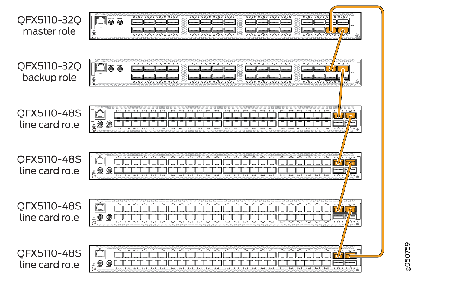
A Juniper Networks QFX5110 Virtual Chassis Fabric (VCF) is constructed using a spine-and-leaf architecture and topology. In the spine-and-leaf architecture, each spine device is interconnected to each leaf device. QFX5110 VCFs support a maximum of 20 members in a VCF. Use QFX5110-32Q as either the spine or as a leaf device. Use QFX5110-48S, QFX5100-24Q, QFX5100-48S, QFX5100-48T, or QFX5100-96S models only as leaf devices.
Figure 3 shows cabling for a QFX5110 VCF with two QFX5110-32Q spine devices connected to four QFX5110-48S as leaf devices, all using all QSFP28 ports as VCPs.Figure 4 shows the cabling for a QFX5110 VCF using QFX5110-32Q as spines and QFX5100-24Q leaf devices.

