Help us improve your experience.

Let us know what you think.

Do you have time for a two-minute survey?


Maintaining the SRX5400 Line Cards and Modules

Holding an SRX5400 Firewall Card

When carrying a card, you can hold it either vertically or horizontally.

Note:

A card weighs up to 18.3 lb (8.3 kg). Be prepared to accept the full weight of the card as you lift it.

To hold a card vertically:

  1. Orient the card so that the faceplate faces you. To verify orientation, confirm that the text on the card is right-side up and the EMI strip is on the right-hand side.
  2. Place one hand around the card faceplate about a quarter of the way down from the top edge. To avoid deforming the EMI shielding strip, do not press hard on it.
  3. Place your other hand at the bottom edge of the card.

If the card is horizontal before you grasp it, place your left hand around the faceplate and your right hand along the bottom edge.

To hold a card horizontally:

  1. Orient the card so that the faceplate faces you.

  2. Grasp the top edge with your left hand and the bottom edge with your right hand.

You can rest the faceplate of the card against your body as you carry it.

As you carry the card, do not bump it against anything. Card components are fragile.

Never hold or grasp the card anywhere except those places that this topic indicates are appropriate. In particular, never grasp the connector edge, especially at the power connector in the corner where the connector and bottom edges meet (see Figure 1).
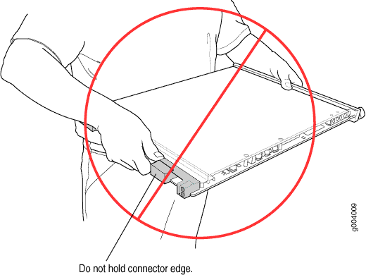
Figure 1: Do Not Grasp the Connector EdgeDo Not Grasp the Connector Edge

Never carry the card by the faceplate with only one hand.

Do not rest any edge of a card directly against a hard surface (see Figure 2).

Do not stack cards.
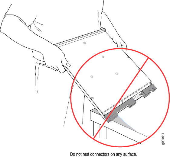
Figure 2: Do Not Rest the Card on an EdgeDo Not Rest the Card on an Edge

If you must rest the card temporarily on an edge while changing its orientation between vertical and horizontal, use your hand as a cushion between the edge and the surface.

Storing an SRX5400 Firewall Card

You must store a card as follows:

  • In the firewall chassis

  • In the container in which a spare card is shipped

  • Horizontally and sheet metal side down

When you store a card on a horizontal surface or in the shipping container, always place it inside an antistatic bag. Because the card is heavy, and because antistatic bags are fragile, inserting the card into the bag is easier with two people. To do this, one person holds the card in the horizontal position with the faceplate facing the body, and the other person slides the opening of the bag over the card connector edge.

If you must insert the card into a bag by yourself, first lay the card horizontally on a flat, stable surface, sheet metal side down. Orient the card with the faceplate facing you. Carefully insert the card connector edge into the opening of the bag, and pull the bag toward you to cover the card.

Never stack a card under or on top of any other component.

Replacing SRX5400 Firewall MPCs

To replace an MPC, perform the following procedures:

Removing an SRX5400 Firewall MPC

An MPC installs horizontally in the front of the firewall. A fully configured MPC can weigh up to 18.35 lb (8.3 kg). Be prepared to accept its full weight.

To remove an MPC:

  1. Have ready a replacement MPC blank panel and an antistatic mat for the MPC. Also have ready rubber safety caps for each MIC using an optical interface on the MPC that you are removing.
  2. Attach an ESD grounding strap to your bare wrist, and connect the other end of the strap to an ESD grounding point.
  3. Label the cables connected to each MIC on the MPC so that you can later reconnect the cables to the correct MICs.
  4. Use one of the following methods to take the MPC offline:
    • Press and hold the corresponding online button on the craft interface. The green OK/FAIL LED next to the button begins to blink. Hold the button down until the LED goes off.

    • Issue the following CLI command:

      user@host>request chassis fpc slot slot-number offline

  5. If you have not already done so, power off the firewall.
  6. Disconnect the cables from the MICs installed in the MPC.
    Laser Warning:

    Do not look directly into a fiber-optic transceiver or into the ends of fiber-optic cables. Fiber-optic transceivers and fiber-optic cables connected to a transceiver emit laser light that can damage your eyes.

    CAUTION:

    Do not leave a fiber-optic transceiver uncovered, except when inserting or removing a cable. The safety cap keeps the port clean and protects your eyes from accidental exposure to laser light.

    CAUTION:

    Avoid bending a fiber-optic cable beyond its minimum bend radius. An arc smaller than a few inches in diameter can damage the cable and cause problems that are difficult to diagnose.

  7. If a MIC uses fiber-optic cable, immediately cover each transceiver and the end of each cable with a rubber safety cap.
  8. Arrange the disconnected cables in the cable management brackets to prevent the cables from developing stress points.
  9. Simultaneously turn both the ejector handles counterclockwise to unseat the MPC.
  10. Grasp the handles, and slide the MPC straight out of the card cage halfway. See Figure 3.
    Figure 3: Removing an MPC Removing an MPC
  11. Place one hand around the front of the MPC (the MIC housing) and the other hand under it to support it. Slide the MPC completely out of the chassis, and place it on the antistatic mat or in the electrostatic bag.
    CAUTION:

    The weight of the MPC is concentrated in the back end. Be prepared to accept the full weight—up to 18.35 lb (8.3 kg)—as you slide the MPC out of the chassis.

    When the MPC is out of the chassis, do not hold it by the ejector handles, bus bars, or edge connectors. They cannot support its weight.

    Do not stack MPCs on top of one another after removal. Place each one individually in an electrostatic bag or on its own antistatic mat on a flat, stable surface.

  12. If necessary, remove each installed MIC from the MPC.
  13. After you remove each MIC, immediately place it on an antistatic mat or in an electrostatic bag.
  14. If you are not reinstalling an MPC into the emptied line card slots within a short time, install a blank DPC panel over each slot to maintain proper airflow in the card cage.

Installing an SRX5400 Firewall MPC

An MPC installs horizontally in the front of the firewall. A fully configured MPC can weigh up to 18.35 lb (8.3 kg). Be prepared to accept its full weight.

To install an MPC:

  1. Attach an ESD grounding strap to your bare wrist, and connect the other end of the strap to an ESD grounding point.
  2. If you have not already done so, power off the firewall.
  3. Place the MPC on an antistatic mat.
  4. Take each MIC to be installed in the replacement MPC out of its electrostatic bag, and identify the slot on the MPC where it will be connected.
  5. Verify that each fiber-optic MIC has a rubber safety cap covering the MIC transceiver. If it does not, cover the transceiver with a safety cap.
  6. Install each MIC into the appropriate slot on the MPC.
  7. Locate the slot in the card cage in which you plan to install the MPC.
  8. Orient the MPC so that the faceplate faces you.
  9. Lift the MPC into place, and carefully align the sides of the MPC with the guides inside the card cage. See Figure 4.
    CAUTION:

    When the MPC is out of the chassis, do not hold it by the ejector handles, bus bars, or edge connectors. They cannot support its weight.

    Figure 4: Installing an MPC in the SRX5400 Firewall Installing an MPC in the SRX5400 Firewall
  10. Slide the MPC all the way into the card cage until you feel resistance.
  11. Grasp both ejector handles, and rotate them clockwise simultaneously until the MPC is fully seated.
  12. If any of the MICs on the MPC connect to fiber-optic cable, remove the rubber safety cap from each transceiver and cable.
    Laser Warning:

    Do not look directly into a fiber-optic transceiver or into the ends of fiber-optic cables. Fiber-optic transceivers and fiber-optic cables connected to a transceiver emit laser light that can damage your eyes.

  13. Insert the appropriate cable into the cable connector ports on each MIC on the MPC. Secure the cables so that they are not supporting their own weight. Place excess cable out of the way in a neatly coiled loop, using the cable management system. Placing fasteners on a loop helps to maintain its shape.
    CAUTION:

    Do not let fiber-optic cables hang free from the connector. Do not allow the fastened loops of a cable to dangle, which stresses the cable at the fastening point.

    CAUTION:

    Avoid bending a fiber-optic cable beyond its minimum bend radius. An arc smaller than a few inches in diameter can damage the cable and cause problems that are difficult to diagnose.

  14. Power on the firewall. The OK LED on the power supply faceplate should blink, then light steadily.
  15. Verify that the MPC is functioning correctly by issuing the show chassis fpc and show chassis fpc pic-status commands. For example:

    Bring the MPC online for the first time by using the following CLI command:

Replacing SRX5400 Firewall MICs

To replace an MIC, perform the following procedures:

Removing an SRX5400 Firewall MIC

The MICs are located in the MPCs installed in the front of the firewall. A MIC weighs less than 2 lb (0.9 kg).

To remove a MIC:

  1. Place an electrostatic bag or antistatic mat on a flat, stable surface to receive the MIC. If the MIC connects to fiber-optic cable, have ready a rubber safety cap for each transceiver and cable.
  2. Attach an ESD grounding strap to your bare wrist, and connect the other end of the strap to an ESD grounding point.
  3. Power off the firewall.
  4. Label the cables connected to the MIC so that you can later reconnect each cable to the correct MIC.
  5. Disconnect the cables from the MIC. If the MIC uses fiber-optic cable, immediately cover each transceiver and the end of each cable with a rubber safety cap.
    Laser Warning:

    Do not look directly into a fiber-optic transceiver or into the ends of fiber-optic cables. Fiber-optic transceivers and fiber-optic cables connected to a transceiver emit laser light that can damage your eyes.

    CAUTION:

    Do not leave a fiber-optic transceiver uncovered, except when you are inserting or removing cable. The safety cap keeps the port clean and protects your eyes from accidental exposure to laser light.

  6. Arrange the cable to prevent it from dislodging or developing stress points. Secure the cable so that it is not supporting its own weight as it hangs to the floor. Place excess cable out of the way in a neatly coiled loop.
    CAUTION:

    Avoid bending a fiber-optic cable beyond its minimum bend radius. An arc smaller than a few inches in diameter can damage the cable and cause problems that are difficult to diagnose.

  7. On the MPC, pull the ejector knob that is adjacent to the MIC you are removing away from the MPC faceplate. The ejector knob is located between the MIC and the rotational knob that retains the MPC in the firewall card cage. Pulling the ejector knob unseats the MIC from the MPC and partially ejects it. See Figure 5.
    Figure 5: Removing a MIC Removing a MIC
  8. Grasp the handles on the MIC faceplate, and slide the MIC out of the MPC card carrier. Place it in the electrostatic bag or on the antistatic mat.
  9. If you are not reinstalling a MIC into the emptied MIC slot within a short time, install a blank MIC panel over the slot to maintain proper airflow in the MPC card cage.

Installing an SRX5400 Firewall MIC

To install a MIC:

  1. Attach an ESD grounding strap to your bare wrist, and connect the other end of the strap to an ESD grounding point.
  2. If you have not already done so, power off the firewall.
  3. If the MIC uses fiber-optic cable, verify that a rubber safety cap is over each transceiver on the faceplate. Install a cap if necessary.
  4. On the MPC, pull the ejector knob that is adjacent to the MIC you are installing away from the MPC faceplate. The ejector knob is located between the MIC and the rotational knob that retains the MPC in the firewall card cage. See Figure 6.
    Figure 6: Installing a MIC Installing a MIC
  5. Align the rear of the MIC with the guides located at the corners of the MIC slot.
  6. Slide the MIC into the MPC until it is firmly seated in the MPC. The ejector knob will automatically move in towards the faceplate to lock the MIC in position as it seats.

    If the MIC does not seat properly in the slot, pull the ejector knob all the way out and try again to seat the MIC. The MIC will not seat properly unless the ejector knob is all the way when you start to insert the MIC.

    CAUTION:

    Slide the MIC straight into the slot to avoid damaging the components on the MIC.

  7. After the MIC is seated in its slot, verify that the ejector knob is engaged by pushing it all the way in toward the MPC faceplate.
  8. If the MIC uses fiber-optic cable, remove the rubber safety cap from each transceiver and the end of each cable.
    Laser Warning:

    Do not look directly into a fiber-optic transceiver or into the ends of fiber-optic cables. Fiber-optic transceivers and fiber-optic cables connected to a transceiver emit laser light that can damage your eyes.

    CAUTION:

    Do not leave a fiber-optic transceiver uncovered, except when you are inserting or removing cable. The safety cap keeps the port clean and protects your eyes from accidental exposure to laser light.

  9. Insert the appropriate cables into the cable connectors on the MIC.
  10. Arrange each cable to prevent the cable from dislodging or developing stress points. Secure the cable so that it is not supporting its own weight as it hangs to the floor. Place excess cable out of the way in a neatly coiled loop.
    CAUTION:

    Do not let fiber-optic cables hang free from the connector. Do not allow the fastened loops of a cable to dangle, which stresses the cable at the fastening point.

    CAUTION:

    Avoid bending a fiber-optic cable beyond its minimum bend radius. An arc smaller than a few inches in diameter can damage the cable and cause problems that are difficult to diagnose.

  11. Power on the firewall. The OK LED on the power supply faceplate should blink, then light steadily.
  12. Verify that the MPC and MICs are functioning correctly by issuing the show chassis fpc and show chassis fpc pic-status commands.

Installing an MPC and MICs in an Operating SRX5400 Firewall Chassis Cluster

If your firewall is part of a chassis cluster, you can install an additional MPC in the firewalls in the cluster without incurring downtime on your network.

Such an installation meet the following conditions:

  • Each of the firewalls in the cluster has an unoccupied slot for the MPC.

  • If the chassis cluster is operating in active-active mode, you must transition it to active-passive mode before using this procedure. You transition the cluster to active-passive mode by making one node primary for all redundancy groups.

  • Both of the firewalls in the cluster must be running Junos OS Release 12.1X45-D10 or later.

If your installation does not meet these criteria, use the procedure in Installing an SRX5400 Firewall MPC to install MPCs in your firewall.

Note:

During this installation procedure, you must shut down both devices, one at a time. During the period when one device is shut down, the remaining device operates without a backup. If that remaining device fails for any reason, you incur network downtime until you restart at least one of the devices.

To install MPCs in an operating SRX5400 Firewall cluster without incurring downtime:

  1. Use the console port on the Routing Engine to establish a CLI session with one of the devices in the cluster.
  2. Issue the show chassis cluster status command to determine which firewall is currently primary, and which firewall is secondary, within the cluster.

    In the example below, all redundancy groups are primary on node 0, and secondary on node 1:

  3. If the device with which you established the CLI session in Step 2 is not the secondary node in the cluster, use the console port on the device that is the secondary node to establish a CLI session.
  4. In the CLI session for the secondary firewall, issue the request system power off command to shut down the firewall.
  5. Wait for the secondary firewall to completely shut down.
  6. Install the new MPCs in the powered-off firewall using the procedure in Installing an SRX5400 Firewall MPC.
  7. Install MICs in the MPCs in the powered-off firewall using the procedure in Installing an SRX5400 Firewall MIC.
  8. Power on the secondary firewall and wait for it to finish starting.
  9. Reestablish the CLI session with the secondary node device.
  10. Issue the show chassis fpc pic-status command to make sure that all of the cards in the secondary node chassis are back online. For example:
  11. Issue the show chassis cluster status command to make sure that the priority for all redundancy groups is greater than zero.
  12. Use the console port on the device that is the primary node to establish a CLI session.
  13. In the CLI session for the primary node device, issue the request chassis cluster failover command to fail over each redundancy group that has an ID number greater than zero.

    For example:

  14. In the CLI session for the primary node device, issue the request system power off command to shut down the firewall. This action causes redundancy group 0 to fail over onto the other firewall, making it the active node in the cluster.
  15. Repeat Step 6 to install MPCs in the powered-off firewall.
  16. Repeat Step 7 to install MICs in the MPCs in the powered-off firewall.
  17. Power on the firewall and wait for it to finish starting.
  18. Issue the show chassis fpc pic-status command on each node to confirm that all cards are online and both firewalls are operating correctly. For example:
  19. Issue the show chassis cluster status command to make sure that the priority for all redundancy groups is greater than zero.

Maintaining SPCs on the SRX5400 Firewall

Purpose

For optimum firewall performance, verify the condition of the Services Processing Cards (SPCs). The firewall can have up to three FPCs (two SPCs) mounted horizontally in the card cage at the front of the chassis. To maintain SPCs, perform the following procedures regularly.

Action

On a regular basis:

  • Check the LEDs on the craft interface corresponding to each SPC slot. The green LED labeled OK lights steadily when an SPC is functioning normally.

  • Check the OK/FAIL LED on the faceplate of each SPC. If the SPC detects a failure, it sends an alarm message to the Routing Engine.

  • Issue the CLI show chassis fpc command to check the status of installed SPCs. As shown in the sample output, the value Online in the column labeled State indicates that the SPC is functioning normally:

    For more detailed output, add the detail option. The following example does not specify a slot number, which is optional:

  • Issue the CLI show chassis fpc pic-status command. The slots are numbered 0 through 2, bottom to top:

    For further description of the output from the command, see Junos OS System Basics and Services Command Reference at www.juniper.net/documentation/.

Replacing SRX5400 Firewall SPCs

To replace an SPC, perform the following procedures:

Removing an SRX5400 Firewall SPC

An SPC weighs up to 18.3 lb (8.3 kg). Be prepared to accept its full weight.

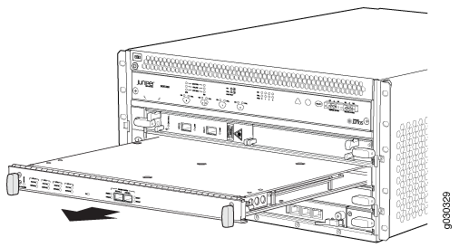
To remove an SPC (see Figure 7):
  1. Have ready a replacement SPC or blank panel and an antistatic mat for the SPC. Also have ready rubber safety caps for each SPC you are removing that uses an optical interface.
  2. Attach an ESD grounding strap to your bare wrist, and connect the other end of the strap to an ESD grounding point.
  3. Power off the firewall using the command request system power-off.
    Note:

    Wait until a message appears on the console confirming that the services stopped.

  4. Physically turn off the power and remove the power cables from the chassis.
  5. Label the cables connected to each port on the SPC so that you can later reconnect the cables to the correct ports.
  6. Disconnect the cables from the SPC. If the SPC uses fiber-optic cable, immediately cover each transceiver and the end of each cable with a rubber safety cap. Arrange the disconnected cables in the cable management system to prevent the cables from developing stress points.
    Laser Warning:

    Do not look directly into a fiber-optic transceiver or into the ends of fiber-optic cables. Fiber-optic transceivers and fiber-optic cables connected to a transceiver emit laser light that can damage your eyes.

    CAUTION:

    Do not leave a fiber-optic transceiver uncovered, except when you are inserting or removing cable. The safety cap keeps the port clean and protects your eyes from accidental exposure to laser light.

    CAUTION:

    Avoid bending a fiber-optic cable beyond its minimum bend radius. An arc smaller than a few inches in diameter can damage the cable and cause problems that are difficult to diagnose.

    CAUTION:

    Do not let fiber-optic cables hang free from the connector. Do not allow the fastened loops of a cable to dangle, which stresses the cable at the fastening point.

  7. Simultaneously turn both of the ejector handles counterclockwise to unseat the SPC.
  8. Grasp the handles and slide the SPC straight out of the card cage halfway.
  9. Place one hand around the front of the SPC and the other hand under it to support it. Slide the SPC completely out of the chassis, and place it on the antistatic mat or in the electrostatic bag.
    CAUTION:

    The weight of the SPC is concentrated in the back end. Be prepared to accept the full weight—up to 18.3 lb (8.3 kg)—as you slide the SPC out of the chassis.

    When the SPC is out of the chassis, do not hold it by the ejector handles, bus bars, or edge connectors. They cannot support its weight.

    Do not stack SPCs on top of one another after removal. Place each one individually in an electrostatic bag or on its own antistatic mat on a flat, stable surface.

  10. If you are not reinstalling an SPC into the empty slot within a short time, install a blank panel over the slot to maintain proper airflow in the card cage.
Figure 7: Removing an SPCRemoving an SPC

Installing an SRX5400 Firewall SPC

To install an SPC (see Figure 8):

  1. Attach an ESD grounding strap to your bare wrist, and connect the other end of the strap to an ESD grounding point.
  2. Power off the firewall using the command request system power-off.
    Note:

    Wait until a message appears on the console confirming that the services stopped.

  3. Physically turn off the power and remove the power cables from the chassis.
  4. Place the SPC on an antistatic mat or remove it from its electrostatic bag.
  5. Identify the slot on the firewall where the SPC will be installed.
  6. Verify that each fiber-optic transceiver is covered with a rubber safety cap. If it does not, cover the transceiver with a safety cap.
  7. Orient the SPC so that the faceplate faces you, the text on the card is right-side up, and the EMI strip is on the right-hand side.
  8. Lift the SPC into place and carefully align the right and left edges of the card with the guides inside the card cage.
  9. Slide the SPC all the way into the card cage until you feel resistance.
  10. Grasp both ejector handles and rotate them clockwise simultaneously until the SPC is fully seated.
  11. If the SPC uses fiber-optic cable, remove the rubber safety cap from each transceiver and cable.
    Laser Warning:

    Do not look directly into a fiber-optic transceiver or into the ends of fiber-optic cables. Fiber-optic transceivers and fiber-optic cables connected to a transceiver emit laser light that can damage your eyes.

  12. Insert the appropriate cables into the cable connector ports on each SPC (see Figure 9). Secure the cables so that they are not supporting their own weight. Place excess cable out of the way in a neatly coiled loop, using the cable management system. Placing fasteners on a loop helps to maintain its shape.
    CAUTION:

    Do not let fiber-optic cables hang free from the connector. Do not allow the fastened loops of a cable to dangle, which stresses the cable at the fastening point.

    CAUTION:

    Avoid bending a fiber-optic cable beyond its minimum bend radius. An arc smaller than a few inches in diameter can damage the cable and cause problems that are difficult to diagnose.

  13. Connect the power cables to the chassis.
  14. Power on the firewall. The OK LED on the power supply faceplate should blink, then light steadily.
  15. Verify that the SPC is functioning correctly by issuing the show chassis fpc and show chassis fpc pic-status commands.
Figure 8: Installing an SPCInstalling an SPC
Figure 9: Attaching a Cable to an SPCAttaching a Cable to an SPC

Replacing SPCs in an Operating SRX5400, SRX5600, or SRX5800 Firewalls Chassis Cluster

If your Firewall is part of an operating chassis cluster, you can replace the first-generation SRX5K-SPC-2-10-40 SPCs with the second generation SRX5K-SPC-4-15-320 SPCs or the first and second generation SPCs with the next generation SRX5K-SPC3s by incurring a minimum downtime on your network.

Note:

SRX5K-SPC-2-10-40 SPC is not supported on SRX5400 Firewall.

To replace SPCs in a firewall that is part of a chassis cluster, it must meet the following conditions:

  • Each firewall must have at least one SPC installed. The installation may warrant additional SPCs if the number of sessions encountered is greater than the session limit of one SPC.

  • If the chassis cluster is operating in active-active mode, you must transition it to active-passive mode before using this procedure. You transition the cluster to active-passive mode by making one node primary for all redundancy groups.

  • To replace first-generation SRX5K-SPC-2-10-40 SPCs, both of the firewalls in the cluster must be running Junos OS Release 11.4R2S1, 12.1R2, or later.

  • To replace second-generation SRX5K-SPC-4-15-320 SPCs, both of the firewalls in the cluster must be running Junos OS Release 12.1X44-D10, or later.

  • To replace next-generation SRX5K-SPC3 SPCs, both of the firewalls in the cluster must be running Junos OS Release 18.2R1-S1, or later.

  • You must install SPCs of the same type and in the same slots in both of the firewalls in the cluster. Both firewalls in the cluster must have the same physical configuration of SPCs.

  • If you are replacing an existing SRX5K-SPC-2-10-40 SPC with an SRX5K-SPC-4-15-320 SPC, you must install the new SPC in the lowest-numbered slot. For example, if the chassis already has SPCs installed in slots 2 and 3, then you must replace the SPC in slot 2 first. This ensures that the central point (CP) functionality is performed by an SRX5K-SPC-4-15-320 SPC.

  • If you are adding SRX5K-SPC3 SPCs for the first time to the chassis which has a mix of other SPCs, you must install the first SRX5K-SPC3 in the lowest-numbered slot first and the other SPX5K-SPC3s can be installed in any available slot. For example, if the chassis already has two SRX5K-SPC-4-15-320 SPCs installed in slots 2 and 3, you must install SRX5K-SPC3 SPCs in slots 0 or 1. You will need to make sure that an SRX5K-SPC3 SPC is installed in the slot providing central point (CP) functionality so that the CP functionality is performed by an SRX5K-SPC3 SPC.

    Note:

    Your firewall cannot have a mix of SRX5K-SPC-2-10-40 SPCs and SRX5K-SPC3 SPCs, but starting with Junos OS release 18.2R2 and then 18.4R1 but not 18.3R1 you can have a mix of SRX5K-SPC-4-15-320 SPCs and SRX5K-SPC3 SPCs.

    If you are adding SRX5K-SPC3s to the chassis which has only SRX5K-SPC3s, the new SRX5K-SPC3 can be installed in any available slot.

  • If you are adding the SRX5K-SPC-4-15-320 SPCs or the SRX5K-SPC3 SPCs to a firewall, the firewall must already be equipped with high-capacity power supplies and fan trays, and the high-capacity air filters. See Upgrading an SRX5600 Firewall from Standard-Capacity to High-Capacity Power Supplies or Upgrading an SRX5600 Firewall from Standard-Capacity to High-Capacity Power Supplies for more information.

If your installation does not meet these criteria, use the procedure in Installing an SRX5400 Firewall SPC, or Installing an SRX5600 Firewall SPC, or Installing an SRX5800 Firewall SPC to install SPCs in your firewall.

Note:

During this installation procedure, you must shut down both devices, one at a time. During the period when one device is shut down, the remaining device operates without a backup. If that remaining device fails for any reason, you incur network downtime until you restart at least one of the devices.

To replace SPCs in an Firewall cluster:

  1. Use the console port on the Routing Engine to establish a CLI session with one of the devices in the cluster.
  2. Use the show chassis cluster status command to determine which firewall is currently primary, and which firewall is secondary, within the cluster.
  3. If the device with which you established the CLI session in Step 2 is not the secondary node in the cluster, use the console port on the device that is the secondary node to establish a CLI session.
  4. Use the show chassis fpc pic-status command to check the status of all the cards on both the nodes.
  5. In the CLI session for the secondary firewall, use the request system power off command to shut down the firewall.
  6. Wait for the secondary firewall to shut down completely and than remove the power cables from the chassis.
  7. Remove the SPC from the powered-off firewall using the procedure in Removing an SRX5400 Firewall SPC, or Removing an SRX5600 Firewall SPC, or Removing an SRX5800 Firewall SPC.
  8. Install the new SPC or SPCs in the powered-off Firewall using the procedure in Installing an SRX5400 Firewall SPC, or Installing an SRX5600 Firewall SPC, or Installing an SRX5800 Firewall SPC.
  9. Insert the power cables to the chassis and power on the secondary firewall and wait for it to finish starting.
  10. Reestablish the CLI session with the secondary node device.
  11. Use the show chassis fpc pic-status command to make sure that all of the cards in the secondary node chassis are back online.
  12. Use the show chassis cluster status command to make sure that the priority for all redundancy groups is greater than zero.
  13. Use the console port on the device that is the primary node to establish a CLI session.
  14. In the CLI session for the primary node device, use the request chassis cluster failover command to fail over each redundancy group that has an ID number greater than zero.
  15. In the CLI session for the primary node device, use the request system power off command to shut down the firewall. This action causes redundancy group 0 to fail over onto the other firewall, making it the active node in the cluster.
  16. Repeat Step 7 and Step 8 to replace or install SPCs in the powered-off firewall.
  17. Power on the firewall and wait for it to finish starting.
  18. Use the show chassis fpc pic-status command on each node to confirm that all cards are online and both firewalls are operating correctly.
  19. Use the show chassis cluster status command to make sure that the priority for all redundancy groups is greater than zero.

In-Service Hardware Upgrade for SRX5K-SPC3 in a Chassis Cluster

If your device is part of a chassis cluster and does not have a mix of SPCs but has only SRX5K-SPC3 SPCs, you can only install additional SRX5K-SPC3 (SPC3) using the In-Service Hardware Upgrade (ISHU) procedure and avoid network downtime.

Note:

This ISHU procedure will not replace any existing Services Processing Cards (SPC), it will guide you to install an additional SPC3 card in a chassis cluster.

Note:

We strongly recommend that you perform the ISHU during a maintenance window, or during the lowest possible traffic as the secondary node is not available at this time.

To install SPC3s in a firewall that is part of a chassis cluster using the ISHU procedure, the following conditions have to be met:

  • Each firewall must have at least one SPC3 installed.

  • Starting in Junos OS Release 19.4R1, ISHU for SRX5K-SPC3 is supported on all SRX5000 line of devices chassis cluster:

    • If the chassis has only one SPC3, you can only install one more SPC3 by using the ISHU procedure.

    • If the chassis already has two SPC3 cards, you cannot install any more SPC3 cards by using the ISHU procedure.

    • If the chassis already has three or more SPC3 cards, you can install additional SPC3 cards by using the ISHU procedure.

  • Installing SPC3s to the chassis cluster must not change the central point (CP) functionality mode from Combo CP mode to Full CP mode.

    When there are two or less than two SPC3s in the chassis, the CP mode is Combo CP mode. More than two SPC3s in the chassis, the CP mode is Full CP mode.

  • If the chassis cluster is operating in active-active mode, you must transition it to active-passive mode before using this procedure. You transition the cluster to active-passive mode by making one node primary for all redundancy groups.

  • When you are adding a new SPC3 to the chassis, it must be installed in the higher numbered slot than the first installed SPC3 in the chassis.

  • The firewall must already be equipped with high-capacity power supplies and fan trays, and the high-capacity air filters. See Upgrading an SRX5600 Firewall from Standard-Capacity to High-Capacity Power Supplies or Upgrading an SRX5600 Firewall from Standard-Capacity to High-Capacity Power Supplies for more information.

During this installation procedure, you must shut down both devices, one at a time. During the period when one device is shut down, the other device operates without a backup. If that other device fails for any reason, you incur network downtime until you restart at least one of the devices.

To add SPC3s in an Firewall cluster without incurring downtime:

  1. Use the console port on the Routing Engine to establish a CLI session with one of the devices in the cluster.
  2. Use the show chassis cluster status command to determine which firewall is currently primary, and which firewall is secondary, within the cluster.
  3. If the device with which you established the CLI session in Step 2 is not the secondary node in the cluster, use the console port on the device that is the secondary node to establish a CLI session.
  4. In the CLI session of the secondary firewall:
    1. Use the show chassis fpc pic-status command to check the status of all the cards on both the nodes.
    2. Use the request vmhost power-off command to shut down the firewall if it has the Routing Engine SRX5K-RE3-128G installed else use the request system power-off command.
  5. Wait for the secondary firewall to shut down completely and than remove the power cables from the chassis.
  6. Install the new SPC3 or SPC3s in the powered-off firewall using the procedure in Installing an SRX5400 Firewall SPC, or Installing an SRX5600 Firewall SPC, or Installing an SRX5800 Firewall SPC.
  7. Insert the power cables to the chassis and power on the secondary firewall and wait for it to finish starting.
  8. Reestablish the CLI session with the secondary node device.
  9. Use the show chassis fpc pic-status command to make sure that all of the cards in the secondary node chassis are back online.
  10. Use the show chassis cluster status command to make sure that the priority for all redundancy groups is greater than zero.
  11. Use the console port on the device that is the primary node to establish a CLI session.
  12. In the CLI session of the primary node:
    1. Use the request chassis cluster failover command to fail over each redundancy group that has an ID number greater than zero.
    2. Use the request vmhost power-off command to shut down the firewall if it has the Routing Engine SRX5K-RE3-128G installed, else use the request system power-off command. This action causes redundancy group 0 to fail over onto the other firewall, making it the active node in the cluster.
  13. Repeat Step 6 to install SPC3s in the powered-off firewall.
  14. Power on the firewall and wait for it to finish starting.
  15. Use the show chassis fpc pic-status command on each node to confirm that all cards are online and both firewalls are operating correctly.
  16. Use the show chassis cluster status command to make sure that the priority for all redundancy groups is greater than zero.