Configure Data Center Interconnect (DCI)
Data Center Interconnect Overview
You can use CEM to interconnect multiple data centers over a WAN such as the Internet or an enterprise network. We support DCI based on EVPN/VXLAN and not Layer 3 VPN and not EVPN/MPLS.
Multiple tenants connected to a logical router (VRF routing instance) in one data center can exchange routes with tenants connected to a logical router in another data center.
The implementation described in this section uses EBGP peering between the data centers.
Data Center Interconnect Configuration Overview
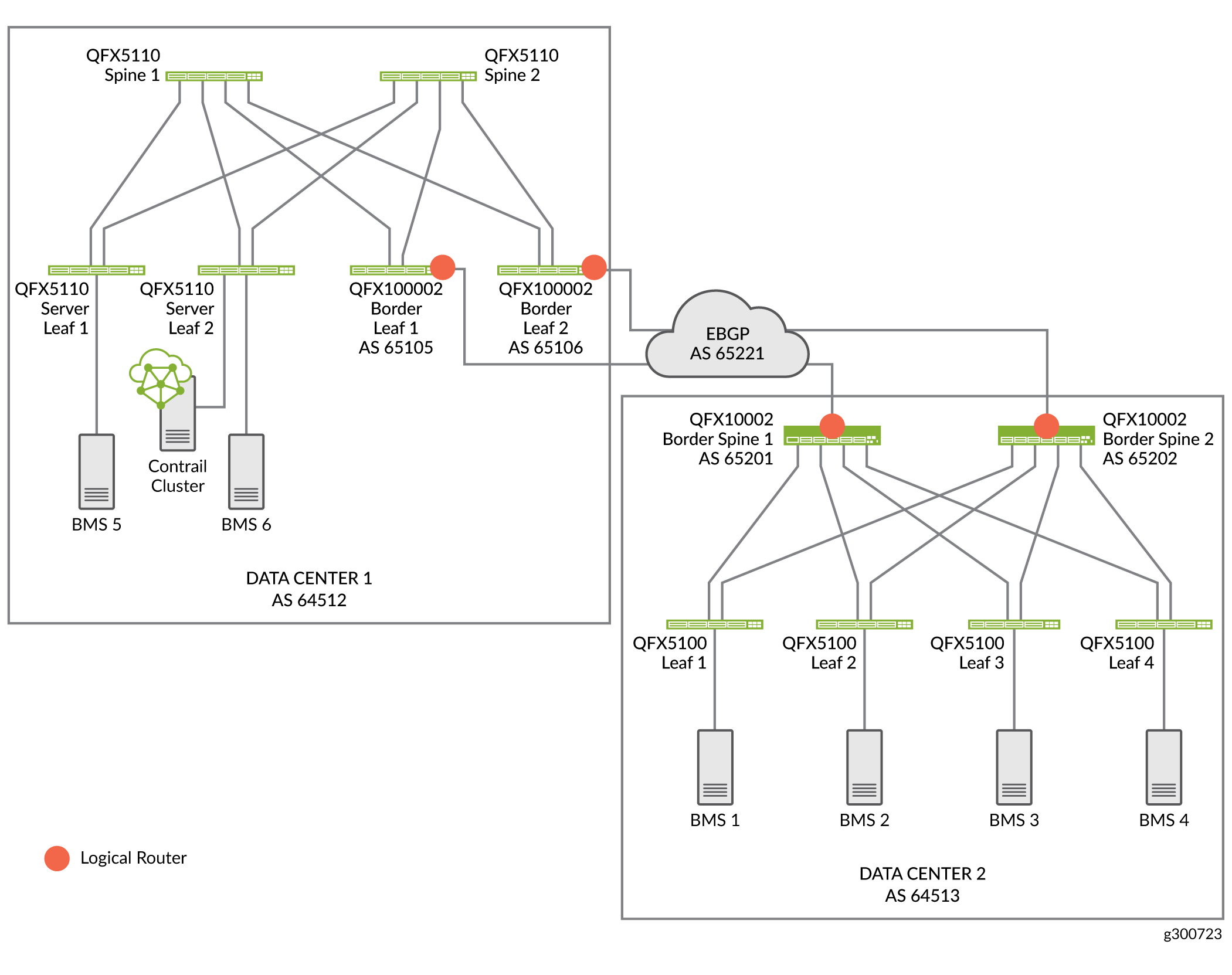
In this example, Figure 1 we are configuring DCI between Data Center 1 (DC1) and Data Center 2 (DC2). Physical connectivity between the data centers is provided by backbone devices in a WAN cloud. In DC1, we are connecting to the WAN cloud from the border leafs. In DCI2, we are connecting to the WAN cloud from the border spines. We are using BGP as the routing protocol between the border devices and the devices in the WAN cloud.
DCI Configuration Overview
With CEM, you can automate data center interconnect (DCI) of two data centers. You can use the same CEM cluster to configure multiple data centers in distinct fabrics.
To configure DCI between Data Center 1 and Data Center 2:
Assign device roles to the spines and border leafs used for DCI
Configure EBGP peering on the underlay
Create virtual networks
Create logical routers
Create Data Center Interconnect
Configure BGP peers on the WAN cloud device.
Assign Device Roles for Border Spine and Border Leaf Devices
In this procedure we assign roles for the border leaf and border spine devices used for DCI.
To assign roles:
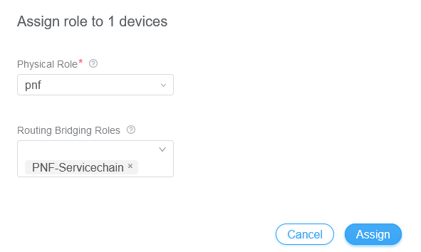
- On the Fabric Devices summary screen, select Action> Reconfigure Roles.
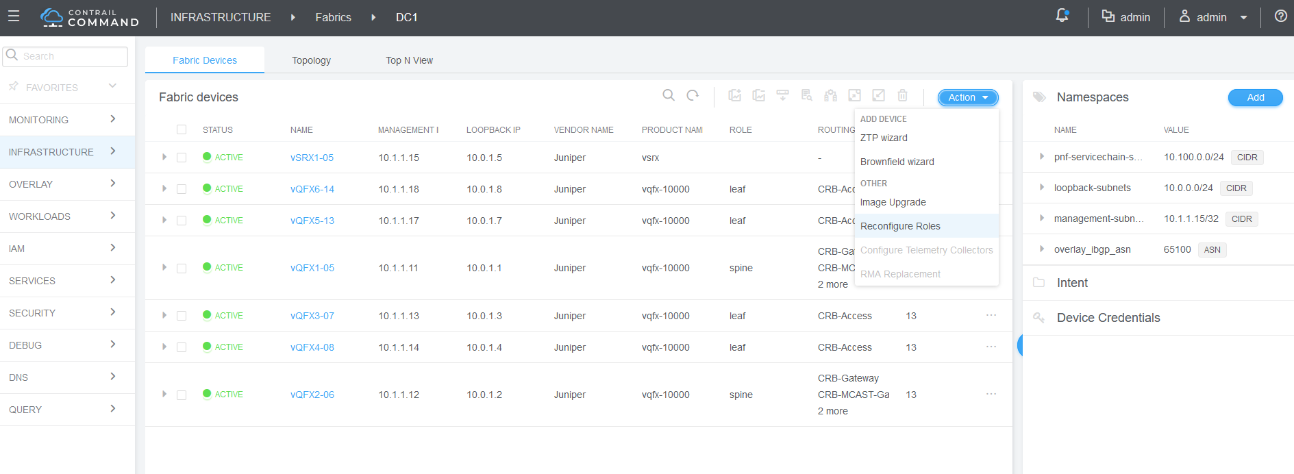
- Next to the spine devices, select Assign Roles.
Manually Configure BGP Peering
When you assign the CRB Gateway or DCI gateway role to a device, CEM autoconfigures IBGP overlay peering between the fabrics. In our implementation, it creates BGP peering between the spine and border leaf devices on DC1 and the border spine devices on DC2.
CEM cannot always configure the underlay automatically when the data centers are not directly connected to each other. In this case, CEM requires loopback-to-loopback reachability between the two data centers on devices with the DCI Gateway role.
We are using an MX Series router as the cloud device. On the cloud device configure the border leaf devices and border spine devices as BGP peers.
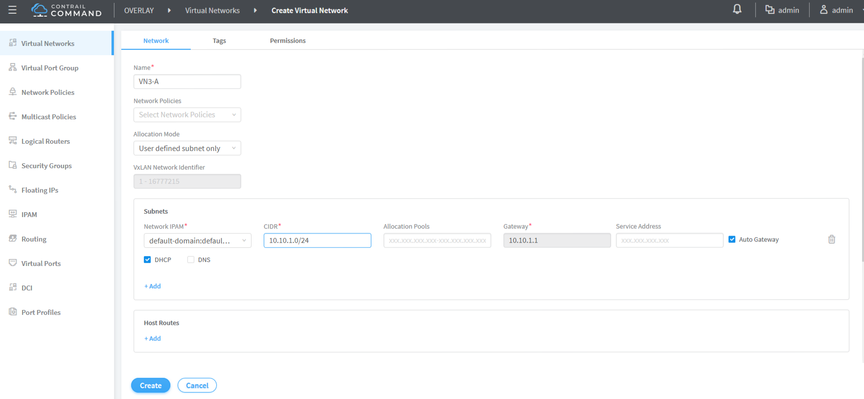
Configure Virtual Networks
We are creating a virtual network in each data center. A virtual network lets hosts in the same network communicate with each other. This is like assigning a VLAN to each host.
To create a virtual network:
- Navigate to Overlay > Virtual Networks and click Create.
The Virtual Networks screen appears.
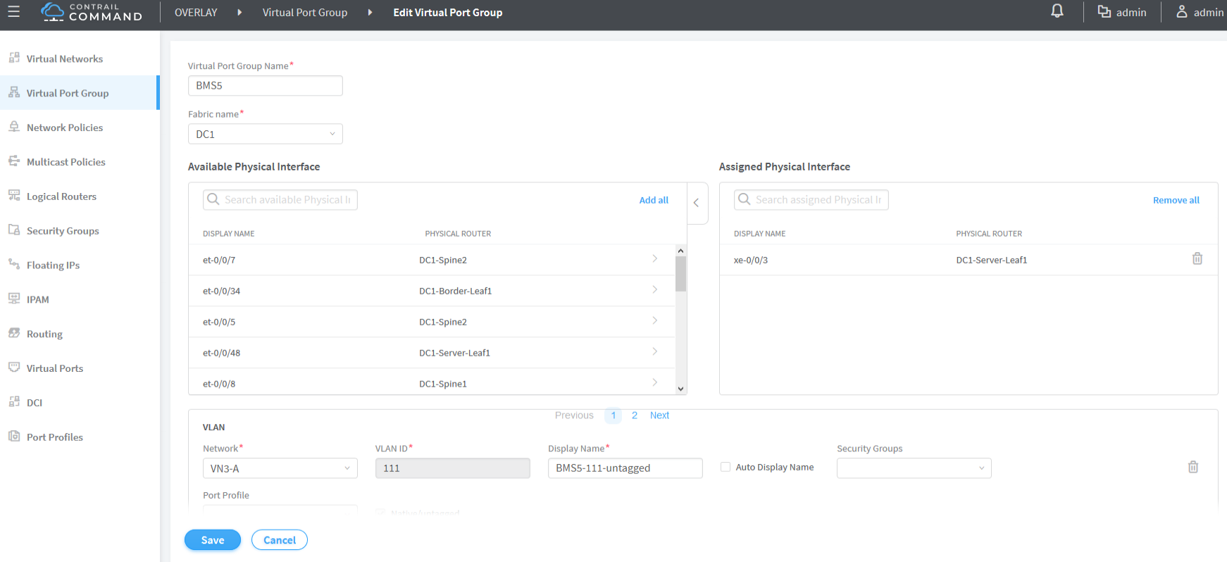
Create Virtual Port Groups
You configure VPGs to add interfaces to your virtual networks. To create a VPG:
- Navigate to Overlay > Virtual Port Group and click Create.
The Create Virtual Port Group screen appears.
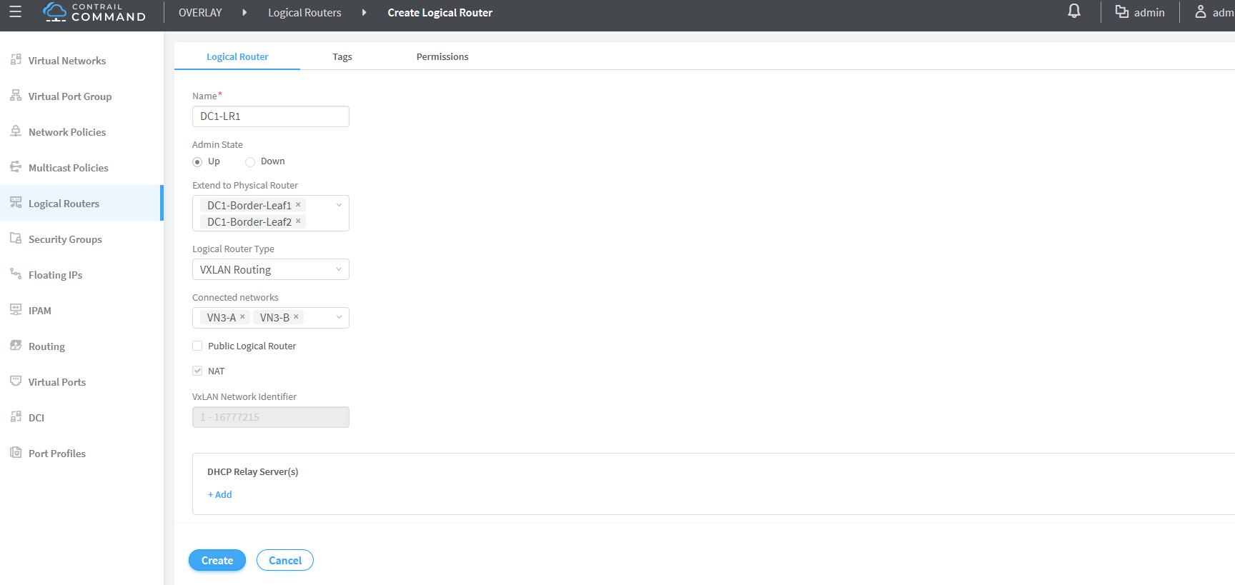
Create Logical Routers
CEM uses logical routers (LRs) to create a virtual routing and forwarding (VRF) routing instance for each logical router with IRB interfaces on the border spine or border leaf devices.
- Navigate to Overlay > Logical Routers and click Create.
The Logical Router screen appears:
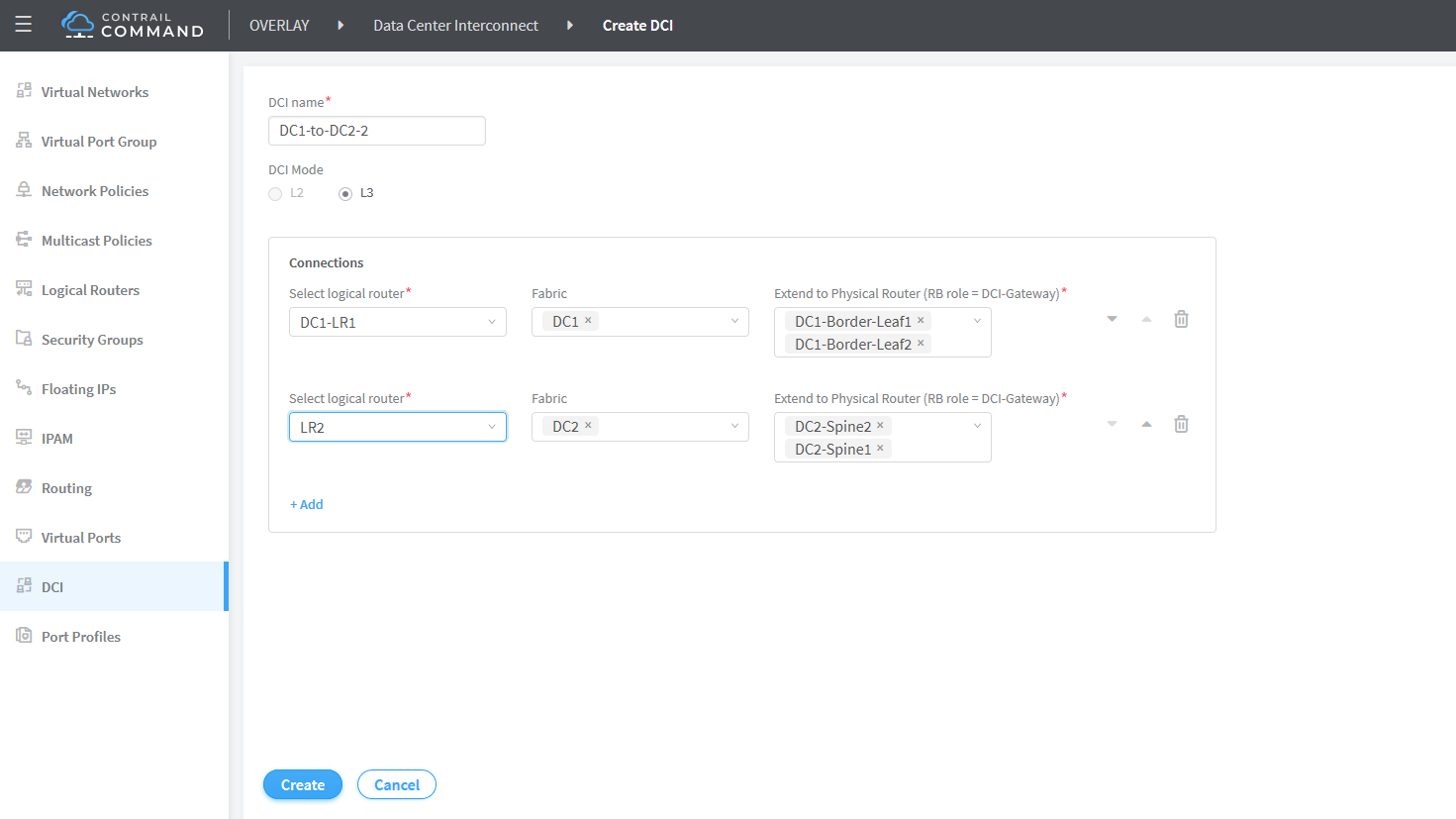
Create Data Center Interconnect
The DCI configuration sets up the connection between
two data centers. Once you add DCI, CEM adds family EVPN to the BGP peers between the border leaf and border spine devices
in DC1 and DC2.
- Fill in the screen as shown:
Verify Data Center Interconnect
To verify that DCI is working, we will ping from a server on a virtual network in one data center to a server on a virtual network in the other data center.