Understanding Automatically Generated ESIs in EVPN Networks
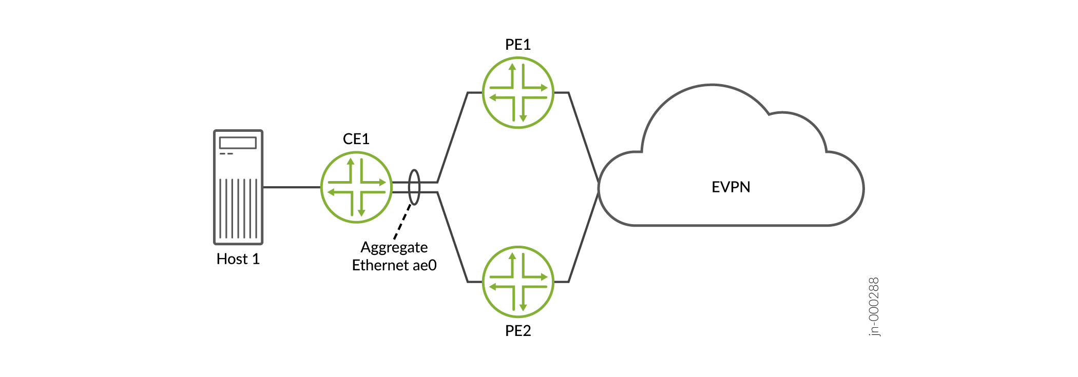
Starting with Junos OS Release 18.4R1, you can configure aggregated Ethernet interfaces and aggregated Ethernet logical interfaces to automatically derive Ethernet segment identifiers (ESIs) from the Link Aggregation Control Protocol (LACP) configuration. Figure 1 shows a simple multihomed network with a customer edge (CE) device multihomed to two provider edge (PE) devices with Link Aggregation Control Protocol (LACP). This feature automatically derives the ESI from the system ID and the administrative key on the local PE device in the LACP link (actor). Starting in Junos OS Release 22.2R1, we support other automatic ESI derivation methods. See Other Methods to Auto-Derive the ESI.
We support this feature on multihomed devices:
-
In all-active mode in an EVPN-VXLAN overlay network.
-
In active-standby or all-active mode in an EVPN-MPLS overlay network.
This topic includes the following information:
Benefits
-
Frees you from manually configuring ESIs in large EVPN-VXLAN and EVPN-MPLS overlay networks,
-
Eliminates the possibility of inadvertently configuring the same ESI for multiple Ethernet segments.
Automatic ESI Configuration
In general, you can configure ESIs on aggregated Ethernet interfaces and aggregated Ethernet logical interfaces using the following methods:
-
Method 1—You can configure automatic ESI on an aggregated Ethernet interface on which LACP is enabled. In this case, an ESI is generated, and that particular ESI is assigned to all logical interfaces on the aggregated Ethernet interface.
-
Method 2—You can configure automatic ESI on one or more logical interfaces of an aggregated Ethernet interface on which LACP is configured. In this case, an ESI is generated for each logical interface on which the feature is enabled and assigned to that particular logical interface.
-
Method 3—On an aggregated Ethernet interface on which LACP is enabled, you can manually configure an ESI using the
esi
                                identifier
configuration statement at the[edit interfaces aeX]hierarchy level. On one or more logical interfaces on that particular aggregated Ethernet interface, you can configure automatic ESI. In this case, an ESI is generated for each logical interface on which the feature is enabled and assigned to that particular logical interface.
Table 1 outlines the automatic ESI configuration options, how to configure each option, and how the ESI is derived for each option.
|
Configuration Options |
How to Configure Automatic ESI |
How ESI Is Derived |
|---|---|---|
|
Configure automatic ESI on an aggregated Ethernet interface on which LACP is enabled. |
Include the |
The ESI is derived from the configured values for the
|
|
Configure automatic ESI on an aggregated Ethernet logical interface. LACP is enabled on the parent aggregated Ethernet interface. |
Include the |
The ESI is derived from the configured values for the
|
Starting in Junos OS Release 22.2R1, the lacp configuration
statement
at the
[edit interfaces interface-name esi
                        auto-derive]
hierarchy level and the [edit interfaces
interface-name unit
logical-unit-number esi auto-derive]
hierarchy level has been
renamed.
The new statement name at those hierarchy levels is
lacp-pe-system-id-and-admin-key.
The CLI aliases the old name to the new name, so you can still commit
configurations that use the old statement name lacp, although
you only see the new name in the
CLI.
When implementing the automatic ESI feature, keep the following in mind:
-
In your EVPN-VXLAN or EVPN-MPLS overlay network, you can configure automatic ESI using a mix of method 1, 2, and 3 configuration use cases.
-
If a local device is multihomed to two remote devices, we recommend that the aggregated Ethernet and aggregated Ethernet logical interfaces by which the three devices are multihomed have the automatic ESI feature enabled. If the automatic ESI feature is not enabled on one of the interfaces, that interface is not considered during the designated forwarder (DF) election process.
-
The automatically generated ESI is supported in both modulo operation- and preference-based DF election processes.
-
If you enable the automatic ESI feature and manually configure an ESI on a particular aggregated Ethernet interface or aggregated Ethernet logical interface, you will receive an error when you try to commit the configuration.
-
If you enable the automatic ESI feature on an aggregated Ethernet interface and one or more of the logical interfaces on that particular aggregated Ethernet interface, you will receive an error when you try to commit the configuration.
Method 1 Sample Configuration—Automatic ESI on An Aggregated Ethernet Interface
The following example shows the configuration of automatic ESI on aggregated Ethernet interface ae0, which is multihomed in all-active mode. This configuration results in an ESI that is automatically generated based on the LACP configuration and assigned to logical interfaces ae0.0, ae0.100, ae0.101, and ae0.102.
user@mx240> show configuration interfaces
ae0
flexible-vlan-tagging;
encapsulation flexible-ethernet-services;
esi {
    auto-derive { ### Automatic ESI configuration.###
        lacp; ### Automatic ESI configuration.###
    }
    all-active;
}
aggregated-ether-options {
    lacp {
        active;
        system-id 00:00:00:00:11:01; ### ESI derived from this value.###
        admin-key 40; ### ESI derived from this value.###
    }
}
unit 0 {
    encapsulation vlan-bridge;
    vlan-id 10;
}
unit 100 {
    family bridge {
        interface-mode trunk;
        vlan-id-list 100;
    }
}
unit 101 {
    family bridge {
        interface-mode trunk;
        vlan-id-list 101;
    }
}
unit 102 {
    family bridge {
        interface-mode trunk;
        vlan-id-list 102;
    }
}
...
Method 2 Sample Configuration—Automatic ESI On Aggregated Ethernet Logical Interfaces
The following example shows the configuration of automatic ESI on aggregated Ethernet logical interfaces ae0.0, ae0.100, ae0.101, and ae0.102, all of which are multihomed in all-active mode. This configuration results in ESIs that are automatically generated based on the LACP and VLAN ID configurations and assigned to each respective logical interface.
user@mx240> show configuration interfaces
ae0
flexible-vlan-tagging;
encapsulation flexible-ethernet-services;
aggregated-ether-options {
    lacp {
        active;
        system-id 00:00:00:00:11:01; ### ESI derived from this value.###
    }
}
unit 0 {
    encapsulation vlan-bridge;
    vlan-id 10; ### ESI derived from this value.###
    esi {
        auto-derive { ### Automatic ESI configuration.###
            lacp; ### Automatic ESI configuration.###
        }
        all-active;
    }
}
unit 100 {
    esi {
        auto-derive { ### Automatic ESI configuration.###
            lacp; ### Automatic ESI configuration.###
        }
        all-active;
    }
    family bridge {
        interface-mode trunk;
        vlan-id-list 100; ### ESI derived from this value.###
    }
}
unit 101 {
    esi {
        auto-derive { ### Automatic ESI configuration.###
            lacp; ### Automatic ESI configuration.###
        }
        all-active;
    }
    family bridge {
        interface-mode trunk;
        vlan-id-list 101; ### ESI derived from this value.###
    }
}
unit 102 {
    esi {
        auto-derive { ### Automatic ESI configuration.###
            lacp; ### Automatic ESI configuration.###
        }
        all-active;
    }
    family bridge {
        interface-mode trunk;
        vlan-id-list 102; ### ESI derived from this value.###
    }
}
...
Method 3 Sample Configuration—Manual ESI on Aggregated Ethernet Interface and Automatic ESI on Logical Interfaces
The following example shows the manual configuration of an ESI on aggregrated Ethernet interface ae0, and the configuration of automatic ESI on logical interfaces ae0.0, ae0.100, ae0.101, and ae0.102. All interfaces are multihomed in all-active mode. This configuration results in ESI 00:11:22:33:44:55:66:77:88:99 being assigned to ae0, and ESIs that are automatically generated based on the LACP and VLAN ID configurations and assigned to the respective logical interfaces.
user@mx240> show configuration interfaces
ae0
flexible-vlan-tagging;
encapsulation flexible-ethernet-services;
esi 00:11:22:33:44:55:66:77:88:99; ### Manual ESI configuration.###
aggregated-ether-options {
    lacp {
        active;
        system-id 00:00:00:00:11:01; ### Logical interface ESI derived from this value.###
    }
}
unit 0 {
    encapsulation vlan-bridge;
    vlan-id 10; ### Logical interface ESI derived from this value.###
    esi {
        auto-derive { ### Automatic ESI configuration.###
            lacp; ### Automatic ESI configuration.###
        }
        all-active;
    }
}
unit 100 {
    esi {
        auto-derive { ### Automatic ESI configuration.###
            lacp; ### Automatic ESI configuration.###
        }
        all-active;
    }
    family bridge {
        interface-mode trunk;
        vlan-id-list 100; ### Logical interface ESI derived from this value.###
    }
}
unit 101 {
    esi {
        auto-derive { ### Automatic ESI configuration.###
            lacp; ### Automatic ESI configuration.###
        }
        all-active;
    }
    family bridge {
        interface-mode trunk;
        vlan-id-list 101; ### Logical interface ESI derived from this value.###
    }
}
unit 102 {
    esi {
        auto-derive { ### Automatic ESI configuration.###
            lacp; ### Automatic ESI configuration.###
        }
        all-active;
    }
    family bridge {
        interface-mode trunk;
        vlan-id-list 102; ### Logical interface ESI derived from this value.###
    }
}
...
Other Methods to Auto-Derive the ESI
Network operators might not be managing all the devices in an EVPN network but they must still ensure that the ESI is unique. Juniper provides other methods to automatically derive an ESI.
Include the following statements at the [edit interfaces
aeX aggregated-ether-options lacp] hierarchy
level.
-
type-1-lacp—Type 1 uses the system ID and the administrative key on the remote CE device in the LACP link (partner). -
type-3-system-mac—Type 3 uses themacandlocal-discriminatorvalues that are configured on the PE device.
We support configuring type 1 and type 3 auto-derived ESI on multihomed devices in the all-active mode in both EVPN-VXLAN and EVPN-MPLS networks.
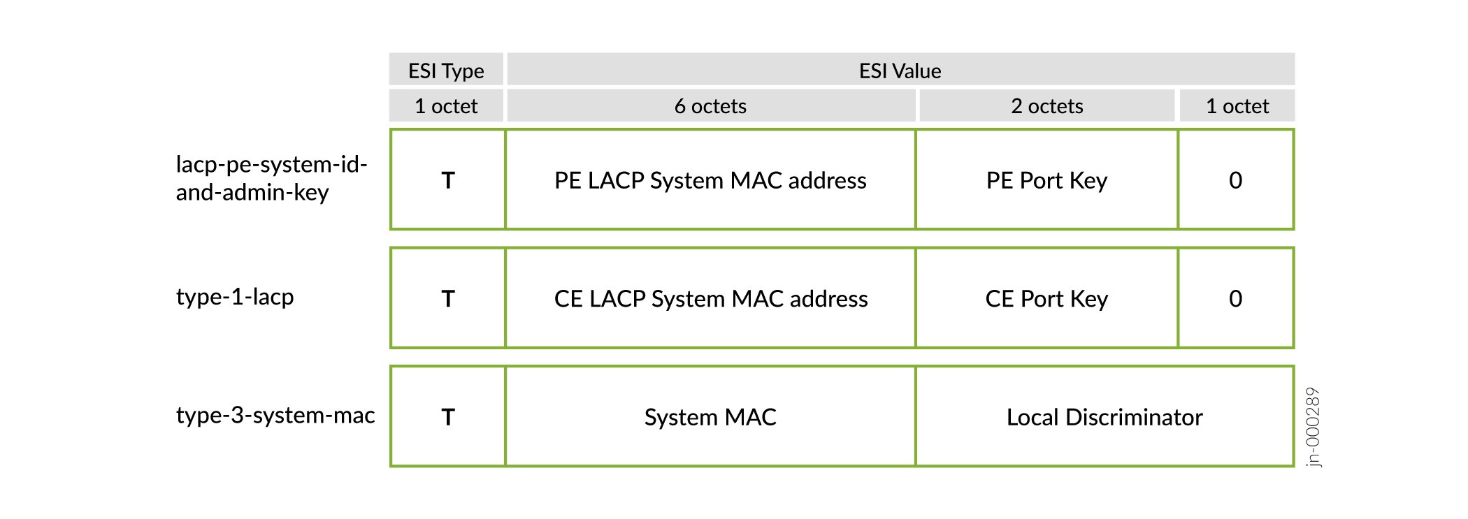
ESI Value Format
When the automatic ESI feature is configured, the aggregated Ethernet and aggregated Ethernet logical interfaces derive the ESIs from various configurations on the aggregated Ethernet interface. The 10-byte ESI value for the different auto-derived ESI options is shown in Figure 2 and described in Table 2.
| Auto-Derived Option | T (ESI Type) | ESI Value |
|---|---|---|
lacp-pe-system-id-and-admin-key
|
Type 1—The first octet is encoded as 0x01. |
The next eight octets are generated from the LACP configuration on the local PE device (actor):
The last octet is encoded as 0x00. |
type-1-lacp
|
Type 1—The first octet is encoded as 0x01. |
The next eight octets are generated from the LACP configuration on the remote CE device (partner):
Note:
The The last octet is encoded as 0x00. |
type-3-system-mac
|
Type 3—The first octet is encoded as 0x03. |
The remaining octets are generated from the values of the
|
Configuring Type 1 and Type 3 Automatic Derivation
Figure 3 show a simple multihomed topology with PE1 and PE2 multihomed to CE1.
Configure Automatic Derivation Using Type 1
The following example shows a type 1 configuration on the aggregated Ethernet interfaces on CE1 and one PE device. The result is an ESI that is derived from the LACP configuration on CE1.
user@pe1 show configuration interfaces ae0
esi {
    auto-derive {
        type-1-lacp;
    }
    all-active;
}
aggregated-ether-options {
    minimum-links 1;
    lacp {
        active;
        system-id 00:11:22:33:44:55; ### system-id must be indentical on PE2
        admin-key 1234;  ### admin-key must be identical on PE2
    }
}
unit 0 {
    family ethernet-switching {
        interface-mode trunk;
        vlan {
            members [ v100 v200 ];
        }
    }
}
...user@ce1# show interfaces ae0
flexible-vlan-tagging;
encapsulation flexible-ethernet-services;
aggregated-ether-options {
lacp {
active;
system-id aa:bb:cc:dd:ee:22; ### ESI derived from this value
admin-key 1234; ### ESI derived from this value
}
}
unit 1 {
vlan-id 100;
family inet {
address 10.1.1.200/24;
}
}
unit 2 {
vlan-id 200;
family inet {
address 10.1.2.200/24;
}
}Configure Automatic Derivation Using Type 3
The following example shows the configuration of automatic ESI on the aggregated Ethernet interface that is using the locally configure system mac and local discriminator options on the PE1 device.
user@pe1# show interfaces ae0
esi {
    auto-derive {
        type-3-system-mac {
            mac 00:aa:bb:cc:dd:ee;  ### ESI derived from this value
            local-discriminator 1000;  ### ESI derived from this value
        }
    }
    all-active;
}
aggregated-ether-options {
    minimum-links 1;
    lacp {
        system-id 00:11:22:33:44:55;
        admin-key 1234;
    }
}
unit 0 {
    family ethernet-switching {
        interface-mode trunk;
        vlan {
            members [ v100 v200 ];
        }
    }
}Change History Table
Feature support is determined by the platform and release you are using. Use Feature Explorer to determine if a feature is supported on your platform.