ON THIS PAGE
Example: Configure an EVPN-VXLAN Centrally-Routed Bridging Fabric
Modern data centers rely on an IP fabric. An IP fabric uses BGP-based Ethernet VPN (EVPN) signaling in the control plane and Virtual Extensible LAN (VXLAN) encapsulation in the data plane. This technology provides a standards-based, high-performance solution for Layer 2 (L2) bridging within a VLAN and for routing between VLANs.
In most cases a one-to-one relationship exists between a user VLAN and a VXLAN network identifier (VNI). As a result, the abbreviations VLAN and VXLAN are often used interchangeably. By default, VXLAN encapsulation strips any ingress VLAN tag when received from an access port. The rest of the Ethernet frame is encapsulated in VXLAN for transport across the fabric. At the egress point, the VXLAN encapsulation is stripped and the VLAN tag (if any) is reinserted before the frame is sent to the attached device.
This is an example of an EVPN-VXLAN IP fabric based on a centrally routed bridging (CRB) architecture. Integrated routing and bridging (IRB) interfaces provide Layer 3 (L3) connectivity to servers and VMs that belong to different VLANs and networks. These IRB interfaces serve as the default gateway for inter-VLAN traffic within a fabric. They also serve as destinations that are remote to the fabric, such as in the case of Data Center Interconnect (DCI). In a CRB design you define the IRB interfaces on the spine devices only. Such a design is therefore referred to as being centrally routed, as all routing occurs on the spines.
For an example of an edge-routed bridging (ERB) design, see Example: Configuring an EVPN-VXLAN Edge-Routed Bridging Fabric with an Anycast Gateway
For background information about EVPN-VXLAN technology and supported architectures, see EVPN Primer.
Requirements
The original example used the following hardware and software components:
-
Two QFX10002 switches (Spine 1 and Spine 2) running Junos OS Release 15.1X53-D30 software.
-
Four QFX5100 switches (Leaf 1 through Leaf 4) running Junos OS Release 14.1X53-D30 software.
-
Updated and re-validated using Junos OS Release 20.4R1.
-
See the hardware summary for a list of supported platforms.
-
Overview
In this example, physical servers that support three groups of users (meaning three VLANs) require the following connectivity:
- Servers A and C should be able to communicate at L2. These servers must share a subnet, and therefore, a VLAN.
- Servers B and D must be on separate VLANs to isolate broadcast. These servers must be able to communicate atL3.
- Servers A and C should not be able to communicate with Servers B and D.
To meet these connectivity requirements these protocols and technologies are used:
-
EVPN establishes an L2 virtual bridge to connect servers A and C and places servers B and D into their respective VLANs.
-
Within the EVPN topology, BGP exchanges route information.
-
VXLAN tunnels the L2 frames through the underlying L3 fabric. The use of VXLAN encapsulation preserves the L3 fabric for use by routing protocols.
-
IRB interfaces route IP packets between the VLANs.
Again, the IRB interfaces are configured on the spine devices only, for centrally routed bridging (CRB). In this design the spine devices function as L3 gateways for the various servers, VMs, or containerized workloads connected to the access ports on the leaf switches. When the workloads exchange data within their own VLANs, the leaf bridges the traffic. The resulting VXLAN encapsulated traffic is then sent through the spines as underlay (IP) traffic. For intra-VLAN traffic the VXLAN virtual tunnel endpoint (VTEP) functionality of the spine is not used. Intra-VLAN traffic is sent between the VTEPs in the source and destination leaf.
In contrast, inter-VLAN (and inter-fabric) traffic must be routed. This traffic is encapsulated into VXLAN and bridged by the leaf to the spine. The leaves know to send this traffic to the spine because the source, that needs routing targets the destination MAC address of the VLAN's default gateway. In other words, frames that are sent to the IRB's MAC address are forwarded at L2 to the spine device.
At the spine, the L2 encapsulation is removed to accommodate an L3 route lookup in the routing instance associated with the VLAN/IRB. For inter-VLAN traffic the spine determines the destination VLAN and the corresponding VXLAN VNI from its route lookup. The spine then re-encapsulates the traffic and sends it through the underlay to the target leaf or leaves.
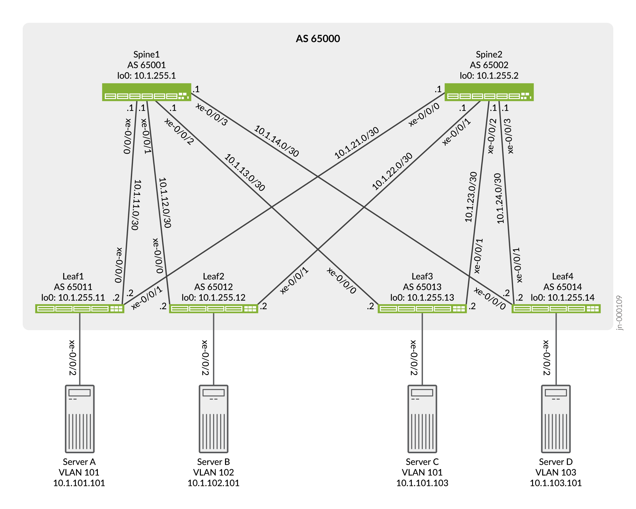
Topology
The simple IP Clos topology shown in Figure 1 includes two spine switches, four leaf switches, and four servers. Each leaf switch has a connection to each of the spine switches for redundancy.
The server networks are segmented into 3 VLANS, each of which is mapped to a VXLAN Virtual Network Identifier (VNI). VLAN v101 supports servers A and C, and VLANs v102 and v103 support servers B and D, respectively. See Table 1 for configuration parameters.
The logical topology shows the expected connectivity. In this example one routing instance is used to connect servers A and C using VLAN 101, and one routing instance is used to connect servers B and D using VLANs 102 and 103. The servers are only able to communicate with other servers that are in the same routing instance by default.
Because servers A and C share the same VLAN, the servers communicate at L2. Therefore, the IRB interface is not needed for servers A and C to communicate. We define an IRB interface in the routing instance as a best practice to enable future L3 connectivity. In contrast, Servers B and D require L3 connectivity through their respective IRB interfaces to communicate, given that these servers are in different VLANs running on unique IP subnets.
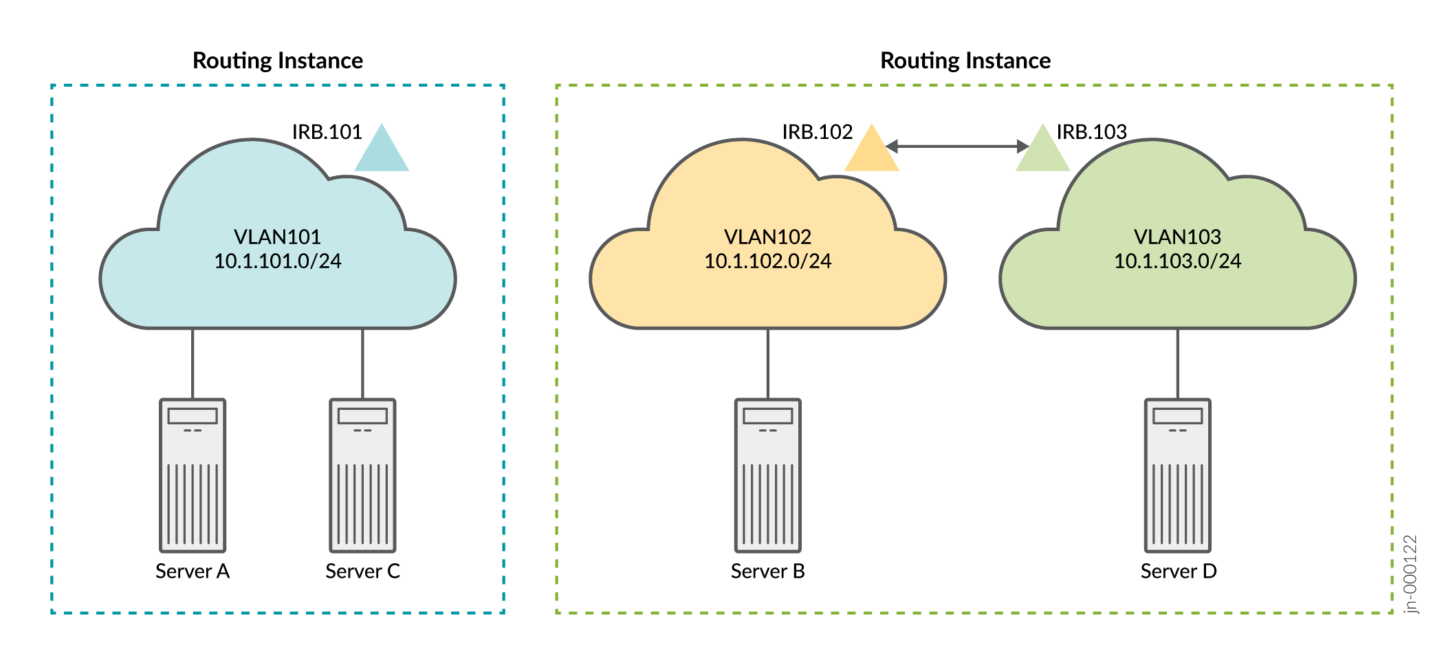
Table 1 provides key parameters, including the IRB interfaces, configured for each network. An IRB interface supports each VLAN and routes data packets over the VLAN from the other VLANs.
|
Parameters |
Servers A and C |
Servers B and C |
|---|---|---|
|
VLAN |
v101 |
v102 |
|
v103 |
||
|
VXLAN VNI |
101 |
102 |
|
103 |
||
|
VLAN ID |
101 |
102 |
|
103 |
||
|
IRB interface |
irb.101 |
irb.102 |
|
irb.103 |
Keep the following in mind when you configure the parameters in Table 1. You must:
-
Associate each VLAN with a unique IP subnet, and therefore a unique IRB interface.
-
Assign each VLAN a unique VXLAN network identifier (VNI).
-
Specify each IRB interface as part of an L3 virtual routing forwarding (VRF) instance, or you can lump the interfaces together in the default switch instance. This example uses VRF instances to enforce separation between the user community (VLANs).
-
Include in the configuration of each IRB interface a default gateway address, which you specify with the
virtual-gateway-addressconfiguration statement at the[interfaces irb unit logical-unit-number family inet address ip-address]hierarchy level. Configuring a virtual gateway sets up a redundant default gateway for each IRB interface.
Spine 1: Underlay Network Configuration
CLI Quick Configuration
To quickly configure this example, copy the following commands, paste them into a text
file, remove any line breaks, change any details necessary to match your configuration,
copy and paste the commands into the CLI at the [edit] hierarchy level,
and then enter commit from configuration mode.
set interfaces xe-0/0/0 unit 0 family inet address 10.1.11.1/30
set interfaces xe-0/0/1 unit 0 family inet address 10.1.12.1/30
set interfaces xe-0/0/2 unit 0 family inet address 10.1.13.1/30
set interfaces xe-0/0/3 unit 0 family inet address 10.1.14.1/30
set interfaces lo0 unit 0 family inet address 10.1.255.1/32 primary
set policy-options policy-statement load-balancing-policy then load-balance per-packet
set policy-options policy-statement send-direct term 1 from protocol direct
set policy-options policy-statement send-direct term 1 then accept
set routing-options router-id 10.1.255.1
set routing-options autonomous-system 65000
set routing-options forwarding-table export load-balancing-policy
set protocols bgp group underlay type external
set protocols bgp group underlay export send-direct
set protocols bgp group underlay local-as 65001
set protocols bgp group underlay multipath multiple-as
set protocols bgp group underlay neighbor 10.1.11.2 peer-as 65011
set protocols bgp group underlay neighbor 10.1.12.2 peer-as 65012
set protocols bgp group underlay neighbor 10.1.13.2 peer-as 65013
set protocols bgp group underlay neighbor 10.1.14.2 peer-as 65014
Spine 1: Configure the Underlay Network
Step-by-Step Procedure
To configure the underlay network on Spine 1:
-
Configure the L3 fabric interfaces.
[edit]
user@Spine1# set interfaces xe-0/0/0 unit 0 family inet address 10.1.11.1/30
user@Spine1# set interfaces xe-0/0/1 unit 0 family inet address 10.1.12.1/30
user@Spine1# set interfaces xe-0/0/2 unit 0 family inet address 10.1.13.1/30
user@Spine1# set interfaces xe-0/0/3 unit 0 family inet address 10.1.14.1/30
-
Specify an IP address for the loopback interface. This IP address serves as the source IP address in the outer header of VXLAN-encapsulated packets.
[edit]
user@Spine1# set interfaces lo0 unit 0 family inet address 10.1.255.1/32 primary
-
Configure the routing options. The configuration includes a reference to a load-balancing policy to enable the use of equal cost multiple path (ECMP) routing through the underlay.
[edit]
user@Spine1# set routing-options router-id 10.1.255.1
user@Spine1# set routing-options autonomous-system 65000
user@Spine1# set routing-options forwarding-table export load-balancing-policy
-
Configure a BGP group for the external BGP (EBGP)-based underlay. Note that multipath is included in the BGP configuration to allow use of multiple equal-cost paths . Normally BGP uses a tie-breaking algorithm that selects the single best path.
[edit]
user@Spine1# set protocols bgp group underlay type external
user@Spine1# set protocols bgp group underlay export send-direct
user@Spine1# set protocols bgp group underlay local-as 65001
user@Spine1# set protocols bgp group underlay multipath multiple-as
user@Spine1# set protocols bgp group underlay neighbor 10.1.11.2 peer-as 65011
user@Spine1# set protocols bgp group underlay neighbor 10.1.12.2 peer-as 65012
user@Spine1# set protocols bgp group underlay neighbor 10.1.13.2 peer-as 65013
user@Spine1# set protocols bgp group underlay neighbor 10.1.14.2 peer-as 65014
-
Configure the per-packet load-balancing policy.
[edit]
user@Spine1# set policy-options policy-statement load-balancing-policy then load-balance per-packet
-
Configure a policy to advertise direct interface routes into the underlay. At a minimum you must advertise the loopback interface (lo0) routes into the underlay.
[edit]
user@Spine1# set policy-options policy-statement send-direct term 1 from protocol direct
user@Spine1# set policy-options policy-statement send-direct term 1 then accept
Spine 1: Overlay Network Configuration
CLI Quick Configuration
To quickly configure this example, copy the following commands, paste the configuration
into a text file, remove any line breaks, change any details necessary to match your
configuration, copy and paste the commands into the CLI at the [edit]
hierarchy level, and then enter commit from configuration mode.
set protocols bgp group evpn type internal
set protocols bgp group evpn local-address 10.1.255.1
set protocols bgp group evpn family evpn signaling
set protocols bgp group evpn cluster 10.1.1.1
set protocols bgp group evpn multipath
set protocols bgp group evpn neighbor 10.1.255.2
set protocols bgp group evpn neighbor 10.1.255.11
set protocols bgp group evpn neighbor 10.1.255.12
set protocols bgp group evpn neighbor 10.1.255.13
set protocols bgp group evpn neighbor 10.1.255.14
set protocols evpn encapsulation vxlan
set protocols evpn default-gateway no-gateway-community
set protocols evpn multicast-mode ingress-replication
set switch-options vtep-source-interface lo0.0
set switch-options route-distinguisher 10.1.255.1:1
set switch-options vrf-target target:65000:1
set switch-options vrf-target auto
Configuring the Overlay Network on Spine 1
Step-by-Step Procedure
To configure the overlay network on Spine 1:
-
Configure an internal BGP (IBGP)-based EVPN-VXLAN overlay. Note that the EVPN address family is configured to support advertisement of EVPN routes. In this case we define an overlay peering to Spine 2 for spine-to-spine connectivity. As with the underlay, we also enabled BGP multipath in the overlay.
Note:Some IP fabrics use an EBGP-based EVPN-VXLAN overlay. For an example of an IP fabric that uses EBGP for both the underlay and overlay, see Example: Configuring an EVPN-VXLAN Edge-Routed Bridging Fabric with an Anycast Gateway. Note that the choice of EBGP or IBGP for the overlay does not negatively affect the fabric architecture. Both centrally routed bridging (CRB) and edge-routed bridging (ERB) designs support either overlay type.
[edit]
user@Spine1# set protocols bgp group evpn type internal
user@Spine1# set protocols bgp group evpn local-address 10.1.255.1
user@Spine1# set protocols bgp group evpn family evpn signaling
user@Spine1# set protocols bgp group evpn cluster 10.1.1.1
user@Spine1# set protocols bgp group evpn multipath
user@Spine1# set protocols bgp group evpn neighbor 10.1.255.2
user@Spine1# set protocols bgp group evpn neighbor 10.1.255.11
user@Spine1# set protocols bgp group evpn neighbor 10.1.255.12
user@Spine1# set protocols bgp group evpn neighbor 10.1.255.13
user@Spine1# set protocols bgp group evpn neighbor 10.1.255.14
-
Configure VXLAN encapsulation for the L2 frames exchanged between the L2 VXLAN VTEPs.
[edit]
user@Spine1# set protocols evpn encapsulation vxlan
-
Configure the default gateway option
no-gateway-communityfor protocols EVPN.[edit] user@Spine1# set protocols evpn default-gateway no-gateway-community
Note:When a virtual-gateway-address is used, a VRRP based MAC “00:00:5e:00:01:01” is used on both the spines, so MAC sync is not needed. See default gateway for more information.
-
Specify how multicast traffic is replicated in the fabric.
[edit]
user@Spine1# set protocols evpn multicast-mode ingress-replication
-
Configure default routing instance options (virtual switch type).
[edit]
user@Spine1# set switch-options vtep-source-interface lo0.0
user@Spine1# set switch-options route-distinguisher 10.1.255.1:1
user@Spine1# set switch-options vrf-target target:65000:1
user@Spine1# set switch-options vrf-target auto
Spine 1: Access Profile Configuration
CLI Quick Configuration
The access profile or access port configuration involves the settings needed to attach server workloads, BMSs or VMs, to the access (leaf) switches. This step involves definition of the device's VLAN along with the routing instance and IRB configuration that provide user isolation and L3 routing, respectively.
Because this is an example of a centrally routed bridging (CRB) fabric, the routing instances and integrated routing and bridging (IRB) interfaces are defined on the spine devices only. The leaf devices in a CRB fabric have only L2 VXLAN functionality.
To quickly configure this example, copy the following commands, paste the commands into a
text file, remove any line breaks, change any details necessary to match your
configuration, copy and paste the commands into the CLI at the [edit]
hierarchy level, and then enter commit from configuration mode.
When proxy-macip-advertisement is enabled, the L3 gateway advertises MAC and IP routes (MAC+IP type 2 routes) on behalf of L2 VXLAN gateways in EVPN-VXLAN networks. This behavior is not supported on EVPN-MPLS. Starting in Junos OS Release 20.2R2, the following warning message appears when you enable proxy-macip-advertisement:
WARNING: Only EVPN VXLAN supports proxy-macip-advertisement configuration,
The message appears when you change your configuration, save your configuration, or use the show command to display your configuration
set interfaces irb unit 101 proxy-macip-advertisement
set interfaces irb unit 101 virtual-gateway-accept-data
set interfaces irb unit 101 family inet address 10.1.101.1/24 virtual-gateway-address 10.1.101.254
set interfaces irb unit 102 proxy-macip-advertisement
set interfaces irb unit 102 virtual-gateway-accept-data
set interfaces irb unit 102 family inet address 10.1.102.1/24 virtual-gateway-address 10.1.102.254
set interfaces irb unit 103 proxy-macip-advertisement
set interfaces irb unit 103 virtual-gateway-accept-data
set interfaces irb unit 103 family inet address 10.1.103.1/24 virtual-gateway-address 10.1.103.254
set protocols evpn vni-options vni 101 vrf-target target:65000:101
set protocols evpn vni-options vni 102 vrf-target target:65000:102
set protocols evpn vni-options vni 103 vrf-target target:65000:103
set protocols evpn extended-vni-list 101
set protocols evpn extended-vni-list 102
set protocols evpn extended-vni-list 103
set routing-instances serverAC instance-type vrf
set routing-instances serverAC interface irb.101
set routing-instances serverAC route-distinguisher 10.1.255.1:13
set routing-instances serverAC vrf-target target:65000:13
set routing-instances serverBD instance-type vrf
set routing-instances serverBD interface irb.102
set routing-instances serverBD interface irb.103
set routing-instances serverBD route-distinguisher 10.1.255.1:24
set routing-instances serverBD vrf-target target:65000:24
set vlans v101 vlan-id 101
set vlans v101 l3-interface irb.101
set vlans v101 vxlan vni 101
set vlans v102 vlan-id 102
set vlans v102 l3-interface irb.102
set vlans v102 vxlan vni 102
set vlans v103 vlan-id 103
set vlans v103 l3-interface irb.103
set vlans v103 vxlan vni 103
Configuring the Access Profiles for Spine 1
Step-by-Step Procedure
To configure profiles for the server networks:
-
Configure the IRB interfaces that support routing among VLANs 101, 102, and 103.
[edit]
user@Spine1# set interfaces irb unit 101 proxy-macip-advertisement
user@Spine1# set interfaces irb unit 101 virtual-gateway-accept-data
user@Spine1# set interfaces irb unit 101 family inet address 10.1.101.1/24 virtual-gateway-address 10.1.101.254
user@Spine1# set interfaces irb unit 102 proxy-macip-advertisement
user@Spine1# set interfaces irb unit 102 virtual-gateway-accept-data
user@Spine1# set interfaces irb unit 102 family inet address 10.1.102.1/24 virtual-gateway-address 10.1.102.254
user@Spine1# set interfaces irb unit 103 proxy-macip-advertisement
user@Spine1# set interfaces irb unit 103 virtual-gateway-accept-data
user@Spine1# set interfaces irb unit 103 family inet address 10.1.103.1/24 virtual-gateway-address 10.1.103.254
-
Specify which virtual network identifiers (VNIs) are included in the EVPN-VXLAN domain.
[edit]
user@Spine1# set protocols evpn extended-vni-list 101
user@Spine1# set protocols evpn extended-vni-list 102
user@Spine1# set protocols evpn extended-vni-list 103
-
Configure a route target for each VNI.
[edit]
user@Spine1# set protocols evpn vni-options vni 101 vrf-target target:65000:101
user@Spine1# set protocols evpn vni-options vni 102 vrf-target target:65000:102
user@Spine1# set protocols evpn vni-options vni 103 vrf-target target:65000:103
Note:In the original configuration, the spine devices run Junos OS Release 15.1X53-D30, and the leaf devices run 14.1X53-D30. In these software releases, when you include the
vrf-targetconfiguration statement in the[edit protocols evpn vni-options vni]hierarchy level, you must also include theexportoption. Note that later Junos OS releases do not require this option. As a result the configurations in this updated example omit theexportoption. -
Configure the routing instance for servers A and C.
[edit]
user@Spine1# set routing-instances serverAC instance-type vrf
user@Spine1# set routing-instances serverAC interface irb.101
user@Spine1# set routing-instances serverAC route-distinguisher 10.1.255.1:13
user@Spine1# set routing-instances serverAC vrf-target target:65000:13
-
Configure the routing instance for servers B and D.
[edit]
user@Spine1# set routing-instances serverBD instance-type vrf
user@Spine1# set routing-instances serverBD interface irb.102
user@Spine1# set routing-instances serverBD interface irb.103
user@Spine1# set routing-instances serverBD route-distinguisher 10.1.255.1:24
user@Spine1# set routing-instances serverBD vrf-target target:65000:24
-
Configure VLANs v101, v102, and v103, and associate the corresponding VNIs and IRB interfaces with each VLAN.
[edit]
user@Spine1# set vlans v101 vlan-id 101
user@Spine1# set vlans v101 l3-interface irb.101
user@Spine1# set vlans v101 vxlan vni 101
user@Spine1# set vlans v102 vlan-id 102
user@Spine1# set vlans v102 l3-interface irb.102
user@Spine1# set vlans v102 vxlan vni 102
user@Spine1# set vlans v103 vlan-id 103
user@Spine1# set vlans v103 l3-interface irb.103
user@Spine1# set vlans v103 vxlan vni 103
Spine 2: Full Configuration
CLI Quick Configuration
The Spine 2 configuration is similar to that of Spine 1, so we provide the full
configuration instead of a step-by-step configuration. To quickly configure this example,
copy the following commands, paste the commands into a text file, remove any line breaks,
change any details necessary to match your configuration, copy and paste the commands into
the CLI at the [edit] hierarchy level, and then enter
commit from configuration mode.
set interfaces xe-0/0/0 unit 0 family inet address 10.1.21.1/30
set interfaces xe-0/0/1 unit 0 family inet address 10.1.22.1/30
set interfaces xe-0/0/2 unit 0 family inet address 10.1.23.1/30
set interfaces xe-0/0/3 unit 0 family inet address 10.1.24.1/30
set interfaces irb unit 101 proxy-macip-advertisement
set interfaces irb unit 101 virtual-gateway-accept-data
set interfaces irb unit 101 family inet address 10.1.101.2/24 virtual-gateway-address 10.1.101.254
set interfaces irb unit 102 proxy-macip-advertisement
set interfaces irb unit 102 virtual-gateway-accept-data
set interfaces irb unit 102 family inet address 10.1.102.2/24 virtual-gateway-address 10.1.102.254
set interfaces irb unit 103 proxy-macip-advertisement
set interfaces irb unit 103 virtual-gateway-accept-data
set interfaces irb unit 103 family inet address 10.1.103.2/24 virtual-gateway-address 10.1.103.254
set interfaces lo0 unit 0 family inet address 10.1.255.2/32 primary
set policy-options policy-statement load-balancing-policy then load-balance per-packet
set policy-options policy-statement send-direct term 1 from protocol direct
set policy-options policy-statement send-direct term 1 then accept
set routing-instances serverAC instance-type vrf
set routing-instances serverAC interface irb.101
set routing-instances serverAC route-distinguisher 10.1.255.1:13
set routing-instances serverAC vrf-target target:65000:13
set routing-instances serverBD instance-type vrf
set routing-instances serverBD interface irb.102
set routing-instances serverBD interface irb.103
set routing-instances serverBD route-distinguisher 10.1.255.1:24
set routing-instances serverBD vrf-target target:65000:24
set routing-options router-id 10.1.255.2
set routing-options autonomous-system 65000
set routing-options forwarding-table export load-balancing-policy
set protocols bgp group underlay type external
set protocols bgp group underlay export send-direct
set protocols bgp group underlay local-as 65002
set protocols bgp group underlay multipath multiple-as
set protocols bgp group underlay neighbor 10.1.21.2 peer-as 65011
set protocols bgp group underlay neighbor 10.1.22.2 peer-as 65012
set protocols bgp group underlay neighbor 10.1.23.2 peer-as 65013
set protocols bgp group underlay neighbor 10.1.24.2 peer-as 65014
set protocols bgp group evpn type internal
set protocols bgp group evpn local-address 10.1.255.2
set protocols bgp group evpn family evpn signaling
set protocols bgp group evpn cluster 10.2.2.2
set protocols bgp group evpn multipath
set protocols bgp group evpn neighbor 10.1.255.1
set protocols bgp group evpn neighbor 10.1.255.11
set protocols bgp group evpn neighbor 10.1.255.12
set protocols bgp group evpn neighbor 10.1.255.13
set protocols bgp group evpn neighbor 10.1.255.14
set protocols evpn encapsulation vxlan
set protocols evpn default-gateway no-gateway-community
set protocols evpn multicast-mode ingress-replication
set protocols evpn vni-options vni 101 vrf-target target:65000:101
set protocols evpn vni-options vni 102 vrf-target target:65000:102
set protocols evpn vni-options vni 103 vrf-target target:65000:103
set protocols evpn extended-vni-list 101
set protocols evpn extended-vni-list 102
set protocols evpn extended-vni-list 103
set switch-options vtep-source-interface lo0.0
set switch-options route-distinguisher 10.1.255.2:1
set switch-options vrf-target target:65000:1
set switch-options vrf-target auto
set vlans v101 vlan-id 101
set vlans v101 l3-interface irb.101
set vlans v101 vxlan vni 101
set vlans v102 vlan-id 102
set vlans v102 l3-interface irb.102
set vlans v102 vxlan vni 102
set vlans v103 vlan-id 103
set vlans v103 l3-interface irb.103
set vlans v103 vxlan vni 103
Leaf 1: Underlay Network Configuration
CLI Quick Configuration
To quickly configure this example, copy the following commands, paste the commands into a
text file, remove any line breaks, change any details necessary to match your
configuration, copy and paste the commands into the CLI at the [edit]
hierarchy level, and then enter commit from configuration mode.
set interfaces xe-0/0/0 unit 0 family inet address 10.1.11.2/30
set interfaces xe-0/0/1 unit 0 family inet address 10.1.21.2/30
set interfaces lo0 unit 0 family inet address 10.1.255.11/32 primary
set routing-options router-id 10.1.255.11
set routing-options autonomous-system 65000
set routing-options forwarding-table export load-balancing-policy
set protocols bgp group underlay type external
set protocols bgp group underlay export send-direct
set protocols bgp group underlay local-as 65011
set protocols bgp group underlay multipath multiple-as
set protocols bgp group underlay neighbor 10.1.11.1 peer-as 65001
set protocols bgp group underlay neighbor 10.1.21.1 peer-as 65002
set policy-options policy-statement load-balancing-policy then load-balance per-packet
set policy-options policy-statement send-direct term 1 from protocol direct
set policy-options policy-statement send-direct term 1 then accept
Configuring the Underlay Network for Leaf 1
Step-by-Step Procedure
To configure the underlay network for Leaf 1:
-
Configure the L3 interfaces.
[edit]
user@Leaf1# set interfaces xe-0/0/0 unit 0 family inet address 10.1.11.2/30
user@Leaf1# set interfaces xe-0/0/1 unit 0 family inet address 10.1.21.2/30
-
Specify an IP address for the loopback interface. This IP address serves as the source IP address in the outer header of any VXLAN encapsulated packets.
[edit]
user@Leaf1# set interfaces lo0 unit 0 family inet address 10.1.255.11/32 primary
-
Set the routing options.
[edit]
user@Leaf1# set routing-options router-id 10.1.255.11
user@Leaf1# set routing-options autonomous-system 65000
user@Leaf1# set routing-options forwarding-table export load-balancing-policy
-
Configure an external BGP (EBGP) group that includes the spines as peers to handle underlay routing.
[edit]
user@Leaf1# set protocols bgp group underlay type external
user@Leaf1# set protocols bgp group underlay export send-direct
user@Leaf1# set protocols bgp group underlay local-as 65011
user@Leaf1# set protocols bgp group underlay multipath multiple-as
user@Leaf1# set protocols bgp group underlay neighbor 10.1.11.1 peer-as 65001
user@Leaf1# set protocols bgp group underlay neighbor 10.1.21.1 peer-as 65002
-
Configure a policy that spreads traffic across multiple paths between the Juniper Networks switches.
[edit]
user@Leaf1# set policy-options policy-statement load-balancing-policy then load-balance per-packet
-
Configure a policy to advertise direct interface routes. At a minimum the underlay must have full reachability to the device loopback addresses.
[edit]
user@Leaf1# set policy-options policy-statement send-direct term 1 from protocol direct
user@Leaf1# set policy-options policy-statement send-direct term 1 then accept
Leaf 1: Overlay Network Configuration
CLI Quick Configuration
To quickly configure this example, copy the following commands, paste the commands into a
text file, remove any line breaks, change any details necessary to match your
configuration, copy and paste the commands into the CLI at the [edit]
hierarchy level, and then enter commit from configuration mode.
set protocols bgp group evpn type internal
set protocols bgp group evpn local-address 10.1.255.11
set protocols bgp group evpn family evpn signaling
set protocols bgp group evpn multipath
set protocols bgp group evpn neighbor 10.1.255.1
set protocols bgp group evpn neighbor 10.1.255.2
set protocols evpn encapsulation vxlan
set protocols evpn multicast-mode ingress-replication
set switch-options vtep-source-interface lo0.0
set switch-options route-distinguisher 10.1.255.11:1
set switch-options vrf-target target:65000:1
set switch-options vrf-target auto
Configuring the Overlay Network for Leaf 1
Step-by-Step Procedure
To configure the overlay network for Leaf 1:
-
Configure an internal BGP (IBGP) group for the EVPN-VXLAN overlay network.
[edit]
user@Leaf1# set protocols bgp group evpn type internal
user@Leaf1# set protocols bgp group evpn local-address 10.1.255.11
user@Leaf1# set protocols bgp group evpn family evpn signaling
user@Leaf1# set protocols bgp group evpn multipath
user@Leaf1# set protocols bgp group evpn neighbor 10.1.255.1
user@Leaf1# set protocols bgp group evpn neighbor 10.1.255.2
-
Configure VXLAN encapsulation for the data packets exchanged between the EVPN neighbors.
[edit]
user@Leaf1# set protocols evpn encapsulation vxlan
-
Specify how multicast traffic is replicated in the EVPN-VXLAN environment.
[edit]
user@Leaf1# set protocols evpn multicast-mode ingress-replication
-
Configure the default routing instance options (virtual switch type).
[edit]
user@Leaf1# set switch-options vtep-source-interface lo0.0
user@Leaf1# set switch-options route-distinguisher 10.1.255.11:1
user@Leaf1# set switch-options vrf-target target:65000:1
user@Leaf1# set switch-options vrf-target auto
Leaf 1: Access Profile Configuration
CLI Quick Configuration
To quickly configure this example, copy the following commands, paste the commands into a
text file, remove any line breaks, change any details necessary to match your
configuration, copy and paste the commands into the CLI at the [edit]
hierarchy level, and then enter commit from configuration mode.
set interfaces xe-0/0/2 unit 0 family ethernet-switching interface-mode trunk
set interfaces xe-0/0/2 unit 0 family ethernet-switching vlan members 101
set protocols evpn vni-options vni 101 vrf-target target:65000:101
set protocols evpn extended-vni-list 101
set vlans v101 vlan-id 101
set vlans v101 vxlan vni 101
Configuring the Access Profile for Leaf 1
Step-by-Step Procedure
To configure the profile for the server network:
-
Configure anL2 Ethernet interface for the connection with the physical server. This interface is associated with VLAN 101. In this example the access interface is configured as a trunk to support VLAN tagging. Untagged access interfaces are also supported.
[edit]
user@Leaf1# set interfaces xe-0/0/2 unit 0 family ethernet-switching interface-mode trunk
user@Leaf1# set interfaces xe-0/0/2 unit 0 family ethernet-switching vlan members 101
-
Configure a route target for the virtual network identifier (VNI).
[edit]
user@Leaf1# set protocols evpn vni-options vni 101 vrf-target target:65000:101
Note:In the original configuration, the spine devices run Junos OS Release 15.1X53-D30, and the leaf devices run 14.1X53-D30. In these software releases, when you include the
vrf-targetconfiguration statement in the[edit protocols evpn vni-options vni]hierarchy level, you must also include theexportoption. Note that later Junos OS releases do not require this option, as reflected in the updated configurations used in this example. -
Specify which VNIs are included in the EVPN-VXLAN domain.
[edit]
user@Leaf1# set protocols evpn extended-vni-list 101
-
Configure VLAN v101. The VLAN is mapped to the same VXLAN VNI that you configured on the spine devices. Note that the L3 integrated routing and bridging (IRB) interface is not specified on the leaf devices. This is because in centrally routed bridging (CRB) the leaves perform L2 bridging only.
[edit]
user@Leaf1# set vlans v101 vlan-id 101
user@Leaf1# set vlans v101 vxlan vni 101
Leaf 2: Full Configuration
CLI Quick Configuration
The Leaf 2 configuration is similar to that of Leaf 1, so we provide the full
configuration instead of a step-by-step configuration. To quickly configure this example,
copy the following commands, paste the commands into a text file, remove any line breaks,
change any details necessary to match your configuration, copy and paste the commands into
the CLI at the [edit] hierarchy level, and then enter
commit from configuration mode.
set interfaces xe-0/0/0 unit 0 family inet address 10.1.12.2/30
set interfaces xe-0/0/1 unit 0 family inet address 10.1.22.2/30
set interfaces xe-0/0/2 unit 0 family ethernet-switching interface-mode trunk
set interfaces xe-0/0/2 unit 0 family ethernet-switching vlan members 102
set interfaces lo0 unit 0 family inet address 10.1.255.12/32 primary
set policy-options policy-statement load-balancing-policy then load-balance per-packet
set policy-options policy-statement send-direct term 1 from protocol direct
set policy-options policy-statement send-direct term 1 then accept
set routing-options router-id 10.1.255.12
set routing-options autonomous-system 65000
set routing-options forwarding-table export load-balancing-policy
set protocols bgp group underlay type external
set protocols bgp group underlay export send-direct
set protocols bgp group underlay local-as 65012
set protocols bgp group underlay multipath multiple-as
set protocols bgp group underlay as-override
set protocols bgp group underlay neighbor 10.1.12.1 peer-as 65001
set protocols bgp group underlay neighbor 10.1.22.1 peer-as 65002
set protocols bgp group evpn type internal
set protocols bgp group evpn local-address 10.1.255.12
set protocols bgp group evpn family evpn signaling
set protocols bgp group evpn multipath
set protocols bgp group evpn neighbor 10.1.255.1
set protocols bgp group evpn neighbor 10.1.255.2
set protocols evpn encapsulation vxlan
set protocols evpn multicast-mode ingress-replication
set protocols evpn vni-options vni 102 vrf-target target:65000:102
set protocols evpn extended-vni-list 102
set switch-options vtep-source-interface lo0.0
set switch-options route-distinguisher 10.1.255.12:1
set switch-options vrf-target target:65000:1
set switch-options vrf-target auto
set vlans v102 vlan-id 102
set vlans v102 vxlan vni 102
Leaf 3: Full Configuration
CLI Quick Configuration
The Leaf 3 configuration is similar to that of Leaf 1, so we provide the full
configuration instead of a step-by-step configuration. To quickly configure this example,
copy the following commands, paste the commands into a text file, remove any line breaks,
change any details necessary to match your configuration, copy and paste the commands into
the CLI at the [edit] hierarchy level, and then enter
commit from configuration mode.
set interfaces xe-0/0/0 unit 0 family inet address 10.1.13.2/30
set interfaces xe-0/0/1 unit 0 family inet address 10.1.23.2/30
set interfaces xe-0/0/2 unit 0 family ethernet-switching interface-mode trunk
set interfaces xe-0/0/2 unit 0 family ethernet-switching vlan members 101
set interfaces lo0 unit 0 family inet address 10.1.255.13/32 primary
set policy-options policy-statement load-balancing-policy then load-balance per-packet
set policy-options policy-statement send-direct term 1 from protocol direct
set policy-options policy-statement send-direct term 1 then accept
set routing-options router-id 10.1.255.13
set routing-options autonomous-system 65000
set routing-options forwarding-table export load-balancing-policy
set protocols bgp group underlay type external
set protocols bgp group underlay export send-direct
set protocols bgp group underlay local-as 65013
set protocols bgp group underlay multipath multiple-as
set protocols bgp group underlay neighbor 10.1.13.1 peer-as 65001
set protocols bgp group underlay neighbor 10.1.23.1 peer-as 65002
set protocols bgp group evpn type internal
set protocols bgp group evpn local-address 10.1.255.13
set protocols bgp group evpn family evpn signaling
set protocols bgp group evpn multipath
set protocols bgp group evpn neighbor 10.1.255.1
set protocols bgp group evpn neighbor 10.1.255.2
set protocols evpn encapsulation vxlan
set protocols evpn multicast-mode ingress-replication
set protocols evpn vni-options vni 101 vrf-target target:65000:101
set protocols evpn extended-vni-list 101
set switch-options vtep-source-interface lo0.0
set switch-options route-distinguisher 10.1.255.13:1
set switch-options vrf-target target:65000:1
set switch-options vrf-target auto
set vlans v101 vlan-id 101
set vlans v101 vxlan vni 101
Leaf 4: Full Configuration
CLI Quick Configuration
The Leaf 4 configuration is similar to that of Leaf 1, so we provide the full
configuration instead of step-by-step configuration. To quickly configure this example,
copy the following commands, paste the commands into a text file, remove any line breaks,
change any details necessary to match your configuration, copy and paste the commands into
the CLI at the [edit] hierarchy level, and then enter
commit from configuration mode.
set interfaces xe-0/0/0 unit 0 family inet address 10.1.14.2/30
set interfaces xe-0/0/1 unit 0 family inet address 10.1.24.2/30
set interfaces xe-0/0/2 unit 0 family ethernet-switching interface-mode trunk
set interfaces xe-0/0/2 unit 0 family ethernet-switching vlan members 103
set interfaces lo0 unit 0 family inet address 10.1.255.14/32 primary
set policy-options policy-statement load-balancing-policy then load-balance per-packet
set policy-options policy-statement send-direct term 1 from protocol direct
set policy-options policy-statement send-direct term 1 then accept
set routing-options router-id 10.1.255.14
set routing-options autonomous-system 65000
set routing-options forwarding-table export load-balancing-policy
set protocols bgp group underlay type external
set protocols bgp group underlay export send-direct
set protocols bgp group underlay local-as 65014
set protocols bgp group underlay multipath multiple-as
set protocols bgp group underlay neighbor 10.1.14.1 peer-as 65001
set protocols bgp group underlay neighbor 10.1.24.1 peer-as 65002
set protocols bgp group evpn type internal
set protocols bgp group evpn local-address 10.1.255.14
set protocols bgp group evpn family evpn signaling
set protocols bgp group evpn multipath
set protocols bgp group evpn neighbor 10.1.255.1
set protocols bgp group evpn neighbor 10.1.255.2
set protocols evpn encapsulation vxlan
set protocols evpn multicast-mode ingress-replication
set protocols evpn vni-options vni 103 vrf-target target:65000:103
set protocols evpn extended-vni-list 103
set switch-options vtep-source-interface lo0.0
set switch-options route-distinguisher 10.1.255.14:1
set switch-options vrf-target target:65000:1
set switch-options vrf-target auto
set vlans v103 vlan-id 103
set vlans v103 vxlan vni 103
Verification
Confirm that the integrated routing and bridging (IRB) interfaces are working properly:
- Verify the IRB Interfaces
- Verifying the Routing Instances
- Verifying Dynamic MAC Addresses Learning
- Verifying Routes in the Routing Instances
- Verify Connectivity
Verify the IRB Interfaces
Purpose
Verify the configuration of the IRB interfaces on Spine 1 and Spine 2.
Action
From operational mode, enter the show interfaces irb command.
user@Spine1> show interfaces irb
Physical interface: irb, Enabled, Physical link is Up
  Interface index: 640, SNMP ifIndex: 505
  Type: Ethernet, Link-level type: Ethernet, MTU: 1514
  Device flags   : Present Running
  Interface flags: SNMP-Traps
  Link type      : Full-Duplex
  Link flags     : None
  Current address: 02:05:86:71:57:00, Hardware address: 02:05:86:71:57:00
  Last flapped   : Never
    Input packets : 0
    Output packets: 0

  Logical interface irb.101 (Index 558) (SNMP ifIndex 583)
    Flags: Up SNMP-Traps 0x4004000 Encapsulation: ENET2
    Bandwidth: 1Gbps
    Routing Instance: default-switch Bridging Domain: v101
    Input packets : 7
    Output packets: 13
    Protocol inet, MTU: 1514
    Max nh cache: 75000, New hold nh limit: 75000, Curr nh cnt: 2, Curr new hold cnt: 0, NH drop cnt: 0
      Flags: Sendbcast-pkt-to-re, Is-Primary
      Addresses, Flags: Is-Default Is-Preferred Is-Primary
        Destination: 10.1.101/24, Local: 10.1.101.1, Broadcast: 10.1.101.255
        Destination: 10.1.101/24, Local: 10.1.101.254, Broadcast: 10.1.101.255

  Logical interface irb.102 (Index 582) (SNMP ifIndex 584)
    Flags: Up SNMP-Traps 0x4000 Encapsulation: ENET2
    Bandwidth: 1Gbps
    Routing Instance: default-switch Bridging Domain: v102
    Input packets : 2
    Output packets: 6
    Protocol inet, MTU: 1514
    Max nh cache: 75000, New hold nh limit: 75000, Curr nh cnt: 1, Curr new hold cnt: 0, NH drop cnt: 0
      Flags: Sendbcast-pkt-to-re
      Addresses, Flags: Is-Preferred Is-Primary
        Destination: 10.1.102/24, Local: 10.1.102.1, Broadcast: 10.1.102.255
        Destination: 10.1.102/24, Local: 10.1.102.254, Broadcast: 10.1.102.255

  Logical interface irb.103 (Index 580) (SNMP ifIndex 585)
    Flags: Up SNMP-Traps 0x4000 Encapsulation: ENET2
    Bandwidth: 1Gbps
    Routing Instance: default-switch Bridging Domain: v103
    Input packets : 2
    Output packets: 6
    Protocol inet, MTU: 1514
    Max nh cache: 75000, New hold nh limit: 75000, Curr nh cnt: 1, Curr new hold cnt: 0, NH drop cnt: 0
      Flags: Sendbcast-pkt-to-re, Is-Primary
      Addresses, Flags: Is-Default Is-Preferred Is-Primary
        Destination: 10.1.103/24, Local: 10.1.103.1, Broadcast: 10.1.103.255
        Destination: 10.1.103/24, Local: 10.1.103.254, Broadcast: 10.1.103.255
Meaning
The sample output from Spine 1 verifies the following:
-
IRB interfaces irb.101, irb.102, and irb.103 are configured.
-
The physical interface upon which the IRB interfaces are configured is up and running.
-
Each IRB interface is properly mapped to its respective VLAN.
-
The configuration of each IRB interface correctly reflects the IP address and destination (virtual gateway address) assigned to it.
Verifying the Routing Instances
Purpose
Verify that the routing instances for servers A and B, and for servers C and D, are properly configured on Spine 1 and Spine 2.
Action
From operational mode, enter the show route instance
routing-instance-name extensive command routing
instances serversAC and serversBD.
user@Spine1> show route instance serverAC extensive
serverAC:
  Router ID: 10.1.101.1
  Type: vrf               State: Active
  Interfaces:
    irb.101
  Route-distinguisher: 10.1.255.1:12
  Vrf-import: [ __vrf-import-serverAC-internal__ ]
  Vrf-export: [ __vrf-export-serverAC-internal__ ]
  Vrf-import-target: [ target:65000:12 ]
  Vrf-export-target: [ target:65000:12 ]
  Fast-reroute-priority: low
  Tables:
    serverAC.inet.0        : 3 routes (3 active, 0 holddown, 0 hidden)
    serverAC.iso.0         : 0 routes (0 active, 0 holddown, 0 hidden)
    serverAC.inet6.0       : 1 routes (1 active, 0 holddown, 0 hidden)
    serverAC.mdt.0         : 0 routes (0 active, 0 holddown, 0 hidden)
user@Spine1> show route instance serverBD extensive
serverBD:
  Router ID: 10.1.102.1
  Type: vrf               State: Active
  Interfaces:
    irb.102
    irb.103
  Route-distinguisher: 10.1.255.1:34
  Vrf-import: [ __vrf-import-serverBD-internal__ ]
  Vrf-export: [ __vrf-export-serverBD-internal__ ]
  Vrf-import-target: [ target:65000:34 ]
  Vrf-export-target: [ target:65000:34 ]
  Fast-reroute-priority: low
  Tables:
    serverBD.inet.0        : 6 routes (6 active, 0 holddown, 0 hidden)
    serverBD.iso.0         : 0 routes (0 active, 0 holddown, 0 hidden)
    serverBD.inet6.0       : 1 routes (1 active, 0 holddown, 0 hidden)
    serverBD.mdt.0         : 0 routes (0 active, 0 holddown, 0 hidden)
Meaning
In the sample output from Spine 1, the routing instances for servers A and C and for servers B and D show the loopback interface and IRB interfaces that are associated with each group. The output also shows the actual route distinguisher, virtual routing and forwarding (VRF) import, and VRF export policy configuration.
Verifying Dynamic MAC Addresses Learning
Purpose
Verify that for VLANs v101, v102, and v103, a dynamic MAC address is installed in the Ethernet switching tables on all leaves.
Action
From operational mode, enter the show ethernet-switching table
command.
user@Leaf1> show ethernet-switching table

MAC flags (S - static MAC, D - dynamic MAC, L - locally learned, P - Persistent static
           SE - statistics enabled, NM - non configured MAC, R - remote PE MAC, O - ovsdb MAC)


Ethernet switching table : 5 entries, 5 learned
Routing instance : default-switch
   Vlan                MAC                 MAC      Logical                SVLBNH/      Active
   name                address             flags    interface              VENH Index   source
   v101                00:00:5e:00:01:01   DR       esi.1746                            05:00:00:fd:e8:00:00:00:65:00
   v101                00:50:56:93:87:58   D        xe-0/0/2.0
   v101                00:50:56:93:ab:f6   D        vtep.32770                          10.1.255.13
   v101                02:05:86:71:27:00   D        vtep.32771                          10.1.255.1
   v101                02:05:86:71:5f:00   D        vtep.32769                          10.1.255.2
Meaning
The sample output from Leaf 1 indicates that it has learned the MAC address 00:00:5e:00:01:01 for its virtual gateway (IRB). This is the MAC address that the attached servers use to reach their default gateway. Because the same virtual IP/MAC is configured on both spines, the virtual IP is treated as an ESI LAG to support active forwarding to both spines without the risk of packet loops. The output also indicates that Leaf 1 learned the IRB MAC addresses for Spine 1 and Spine 2, which function as VTEPs.
Verifying Routes in the Routing Instances
Purpose
Verify that the correct routes are in the routing instances.
Action
From operational mode, enter the show route table
routing-instance-name.inet.0 command.
user@Spine1> show route table serverAC.inet.0

serverAC.inet.0: 3 destinations, 3 routes (3 active, 0 holddown, 0 hidden)
+ = Active Route, - = Last Active, * = Both

10.1.101.0/24      *[Direct/0] 2d 01:34:44
                    >  via irb.101
10.1.101.1/32      *[Local/0] 2d 01:34:44
                       Local via irb.101
10.1.101.254/32    *[Local/0] 2d 01:34:44
                       Local via irb.101


user@Spine1> show route table serverBD.inet.0

serverBD.inet.0: 6 destinations, 6 routes (6 active, 0 holddown, 0 hidden)
+ = Active Route, - = Last Active, * = Both

10.1.102.0/24      *[Direct/0] 2d 01:34:51
                    >  via irb.102
10.1.102.1/32      *[Local/0] 2d 01:34:51
                       Local via irb.102
10.1.102.254/32    *[Local/0] 2d 01:34:51
                       Local via irb.102
10.1.103.0/24      *[Direct/0] 2d 01:34:51
                    >  via irb.103
10.1.103.1/32      *[Local/0] 2d 01:34:51
                       Local via irb.103
10.1.103.254/32    *[Local/0] 2d 01:34:51
                       Local via irb.103
Meaning
The sample output from Spine 1 indicates that the routing instance for servers A and C has the IRB interface routes associated with VLAN 101 and that the routing instance for server B and D has the IRB interfaces routes associated with VLANs 102 and 103.
Based on the routes in each table, it is clear that servers A and C in VLAN 101 cannot reach servers in C and D in VLANs 102 or 103. The output also shows that the common table that houses routes for servers B and D allows L3 communications through their IRB interfaces.
Verify Connectivity
Purpose
Verify that servers A and C can ping each other and servers B and D can ping each other.
Action
Run the ping command from the servers.
 user@serverA> ping 10.1.101.103 count 2
PING 10.1.101.103 (10.1.101.103): 56 data bytes
64 bytes from 10.1.101.103: icmp_seq=0 ttl=64 time=103.749 ms
64 bytes from 10.1.101.103: icmp_seq=1 ttl=64 time=116.325 ms

--- 10.1.101.103 ping statistics ---
2 packets transmitted, 2 packets received, 0% packet loss
round-trip min/avg/max/stddev = 103.749/110.037/116.325/6.288 ms

user@serverB> ping 10.1.103.101 count 2
PING 10.1.103.101 (10.1.103.101): 56 data bytes
64 bytes from 10.1.103.101: icmp_seq=0 ttl=63 time=103.346 ms
64 bytes from 10.1.103.101: icmp_seq=1 ttl=63 time=102.355 ms

--- 10.1.103.101 ping statistics ---
2 packets transmitted, 2 packets received, 0% packet loss
round-trip min/avg/max/stddev = 102.355/102.851/103.346/0.495 ms
Meaning
The sample output shows that server A can ping server C, and server B can ping server D. Servers A and C should not be able to ping servers B and D, and servers B and D should not be able to ping servers A and C.
Spine 1 and 2: Route Leaking (Optional)
Referring to Figure 2, recall that you configured three VLANs and two routing instances to provide connectivity for servers A and C in VLAN 101 and for servers B and D in VLANs 102 and 103, respectively. In this section you modify the configuration to leak routes between the two routing instances. Figure 3 shows the resulting logical connectivity after the integrated routing and bridging (IRB) routes are leaked.
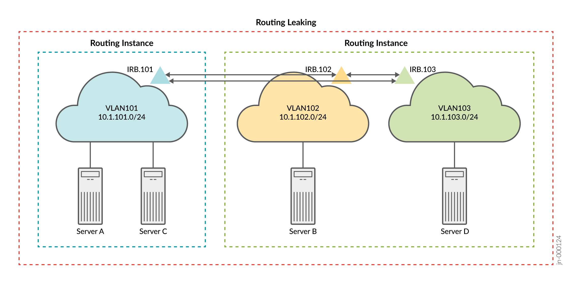
With your routing information base (RIB) group modifications, you can expect the servers in VLAN 101 to reach the servers in both VLANs 102 and 103 using L3 connectivity.
CLI Quick Configuration
At this stage you have deployed a CRB-based EVPN fabric and have confirmed expected
connectivity. That is, servers A and C can communicate at L2. Servers B and D (on VLANs
102 and 103, respectively) communicate through IRB routing in their shared routing
instance. What if you want all servers to be able to ping each other? One option to solve
this problem is to leak the routes between the routing instances. See auto-export for more information about leaking
routes between virtual routing and forwarding (VRF) instances. To quickly configure this
example, copy the following commands, paste the commands into a text file, remove any line
breaks, change any details necessary to match your configuration, copy and paste the
commands into the CLI at the [edit] hierarchy level, and then enter
commit from configuration mode.
set policy-options policy-statement serverAC_vrf_imp term 1 from community serverBD
set policy-options policy-statement serverAC_vrf_imp term 1 then accept
set policy-options policy-statement serverBD_vrf_imp term 1 from community serverAC
set policy-options policy-statement serverBD_vrf_imp term 1 then accept
set policy-options community serverAC members target:65000:13
set policy-options community serverBD members target:65000:24
set routing-instances serverAC routing-options auto-export
set routing-instances serverAC vrf-import serverAC_vrf_imp
set routing-instances serverBD routing-options auto-export
set routing-instances serverBD vrf-import serverBD_vrf_imp
Verification with Route Leaking (Optional)
Verifying Routes with Route Leaking (Optional)
Purpose
Verify that the correct routes are in the routing instances.
Action
From operational mode, enter the show route table
routing-instance-name.inet.0 command.
user@Spine1> show route table serverAC.inet.0

serverAC.inet.0: 9 destinations, 9 routes (9 active, 0 holddown, 0 hidden)
+ = Active Route, - = Last Active, * = Both

10.1.101.0/24      *[Direct/0] 2d 02:18:50
                    >  via irb.101
10.1.101.1/32      *[Local/0] 2d 02:18:50
                       Local via irb.101
10.1.101.254/32    *[Local/0] 2d 02:18:50
                       Local via irb.101
10.1.102.0/24      *[Direct/0] 00:31:21
                    >  via irb.102
10.1.102.1/32      *[Local/0] 00:31:21
                       Local via irb.102
10.1.102.254/32    *[Local/0] 00:31:21
                       Local via irb.102
10.1.103.0/24      *[Direct/0] 00:31:21
                    >  via irb.103
10.1.103.1/32      *[Local/0] 00:31:21
                       Local via irb.103
10.1.103.254/32    *[Local/0] 00:31:21
                       Local via irb.103


user@Spine1> show route table serverBD.inet.0

serverBD.inet.0: 9 destinations, 9 routes (9 active, 0 holddown, 0 hidden)
+ = Active Route, - = Last Active, * = Both

10.1.101.0/24      *[Direct/0] 00:32:00
                    >  via irb.101
10.1.101.1/32      *[Local/0] 00:32:00
                       Local via irb.101
10.1.101.254/32    *[Local/0] 00:32:00
                       Local via irb.101
10.1.102.0/24      *[Direct/0] 2d 02:19:29
                    >  via irb.102
10.1.102.1/32      *[Local/0] 2d 02:19:29
                       Local via irb.102
10.1.102.254/32    *[Local/0] 2d 02:19:29
                       Local via irb.102
10.1.103.0/24      *[Direct/0] 2d 02:19:29
                    >  via irb.103
10.1.103.1/32      *[Local/0] 2d 02:19:29
                       Local via irb.103
10.1.103.254/32    *[Local/0] 2d 02:19:29
                       Local via irb.103
Meaning
The sample output from Spine 1 indicates that both routing instances now have the integrated routing and bridging (IRB) interface routes associated with all three VLANs. Because you copied routes between the instance tables, the net result is the same as if you configured all three VLANs in a common routing instance. Thus, you can expect full L3 connectivity between servers in all three VLANs.
Verifying Connectivity with Route Leaking (Optional)
Purpose
Verify that servers A and C can ping servers B and D.
Action
Run the ping command from the servers.
user@serverA> ping 10.1.102.101 count 2
PING 10.1.102.101 (10.1.102.101): 56 data bytes
64 bytes from 10.1.102.101: icmp_seq=0 ttl=63 time=102.448 ms
64 bytes from 10.1.102.101: icmp_seq=1 ttl=63 time=102.384 ms

--- 10.1.102.101 ping statistics ---
2 packets transmitted, 2 packets received, 0% packet loss
round-trip min/avg/max/stddev = 102.384/102.416/102.448/0.032 ms

user@serverA> ping 10.1.103.101 count 2
PING 10.1.103.101 (10.1.103.101): 56 data bytes
64 bytes from 10.1.103.101: icmp_seq=0 ttl=63 time=103.388 ms
64 bytes from 10.1.103.101: icmp_seq=1 ttl=63 time=102.623 ms

--- 10.1.103.101 ping statistics ---
2 packets transmitted, 2 packets received, 0% packet loss
round-trip min/avg/max/stddev = 102.623/103.006/103.388/0.382 ms

user@serverC> ping 10.1.102.101 count 2
PING 10.1.102.101 (10.1.102.101): 56 data bytes
64 bytes from 10.1.102.101: icmp_seq=0 ttl=63 time=167.580 ms
64 bytes from 10.1.102.101: icmp_seq=1 ttl=63 time=168.075 ms

--- 10.1.102.101 ping statistics ---
2 packets transmitted, 2 packets received, 0% packet loss
round-trip min/avg/max/stddev = 167.580/167.827/168.075/0.248 ms

user@serverC> ping 10.1.103.101 count 2
PING 10.1.103.101 (10.1.103.101): 56 data bytes
64 bytes from 10.1.103.101: icmp_seq=0 ttl=63 time=103.673 ms
64 bytes from 10.1.103.101: icmp_seq=1 ttl=63 time=115.090 ms

--- 10.1.103.101 ping statistics ---
2 packets transmitted, 2 packets received, 0% packet loss
round-trip min/avg/max/stddev = 103.673/109.382/115.090/5.709 ms
Meaning
The sample output shows that server A can ping server B and server D. It also shows that server C can ping server B and server D. This confirms the expected full connectivity among the servers and their VLANs.
Change History Table
Feature support is determined by the platform and release you are using. Use Feature Explorer to determine if a feature is supported on your platform.