ON THIS PAGE
Configuring the Advertisement Interval for the VRRP Primary Router
Configuring a Backup Router to Preempt the VRRP Primary Router
Configuring a Backup to Accept Packets Destined for the Virtual IP Address
Modifying the Preemption Hold-Time Value for the VRRP Primary Router
Configuring a Logical Interface to Be Tracked for a VRRP Group
Configuring an Interface to Accept All Packets Destined for the Virtual IP Address of a VRRP Group
Configuring the Silent Period to Avoid Alarms Due to Delay in Receiving VRRP Advertisement Packets
Enabling the Distributed Periodic Packet Management Process for VRRP
Configuring VRRP
Configure virtual router redundancy protocol (VRRP)_on your device with the steps and examples below.
Configuring Basic VRRP Support
VRRP nonstop active routing (NSR) is enabled only when you configure the
nonstop-routing statement at the [edit routing-options]
or [edit logical system logical-system-name
routing-options] hierarchy level.
The Virtual Router Redundancy Protocol (VRRP) groups multiple routing devices into a virtual router. At any time, one of the VRRP routing platforms is the primary (active) and the others are backups. If the primary fails, one of the backup routing platforms becomes the new primary router.
To configure basic VRRP support, configure VRRP groups on interfaces by including the
vrrp-group statement:
vrrp-group group-id {
    priority number;
    virtual-address [ addresses ];
}
An interface can be a member of multiple VRRP groups. Within a VRRP group, the primary virtual router and the backup virtual router must be configured on different routing platforms.
You can include this statement at the following hierarchy level:
-
[edit interfaces interface-name unit
              logical-unit-number family inet address
            address]
We recommend only assigning one interface per VRRP group. All configured interfaces in a VRRP group will fail if the primary device goes down, which can cause issues with the failover process if multiple interfaces are configured.
Mandatory parameters to configure a VRRP group are as follows (examples will follow):
Configure the group identifier (mandatory).
Configure the group:
Configure the virtual IP address of one or more virtual routers that are members of the VRRP group (mandatory).
Configure the virtual link-local address (VRRP for IPv6 only). The virtual link-local address is autogenerated when you enable VRRPv3 on the interface. You may explicitly define a virtual link-local address for each VRRP for the IPv6 group. The virtual link-local address must be on the same subnet as the physical interface address.
When choosing a VRRP group identifier, consider the following:
-
If
network-servicesis configured in IP mode, don't configure the same VRRP group ID for multiple VRRP sessions on the same physical interface unless VRRP delegation is disabled. If multiple VRRP sessions are configured on the same physical interface with the same VRRP group ID while VRRP delegation is enabled, the other VRRP virtual IP addresses become unreachable when one of the logical interfaces is deleted. -
If
network-servicesis configured in enhanced-ip mode, you can use the same VRRP group ID for multiple VRRP sessions.
When configuring a virtual IP address, consider the following:
-
The virtual IP address must be the same for all routing platforms in the VRRP group.
-
If you configure a virtual IP address to be the same as the physical interface’s address, the interface becomes the primary virtual router for the group. In this case, you must configure the priority to be 255, and you must configure preemption by including the
preemptstatement. -
If the virtual IP address you choose is not the same as the physical interface’s address, you must ensure that the virtual IP address does not appear anywhere else in the routing platform’s configuration. Verify that you do not use this address for other interfaces, for the IP address of a tunnel, or for the IP address of static ARP entries.
-
You cannot configure a virtual IP address to be the same as the interface’s address for an aggregated Ethernet interface. This configuration is not supported.
-
For VRRP for IPv6, the
EUI-64option cannot be used. In addition, the Duplicate Address Detection (DAD) process will not run for virtual IPv6 addresses. -
You cannot configure the same virtual IP address on interfaces that belong to the same logical system and routing instance combination. However, you can configure the same virtual IP address on interfaces that belong to different logical systems and routing instance combinations.
In determining what priority will make a given routing platform in a VRRP group a primary or backup, consider the following:
-
You can force assignment of primary and backup routers using priorities from 1 through 255, where 255 is the highest priority.
-
The priority value for the VRRP router that owns the IP address(es) associated with the virtual router must be 255.
-
VRRP routers backing up a virtual router must use priority values from 1 through 254.
-
The default priority value for VRRP routers backing up a virtual router is 100.
-
Are there tracked interfaces or routes with priority costs?
The priority cost is the value associated with a tracked logical interface or route that is to be subtracted from the configured VRRP priority when the tracked logical interface or route goes down, forcing a new primary router election. The value of a priority cost can be from 1 through 254. The sum of the priority costs for all tracked logical interfaces or routes must be less than or equal to the configured priority of the VRRP group.
Mixed tagging (configuring two logical interfaces on the same Ethernet port, one with
single-tag framing and one with dual-tag framing) is supported only for interfaces on
Gigabit Ethernet IQ2 and IQ PICs. If you include the
flexible-vlan-tagging statement at the [edit interfaces
interface-name] hierarchy level for a VRRP-enabled
interface on a PIC that does not support mixed tagging, VRRP on that interface is
disabled. In the output of the show vrrp summary operational command, the
interface status is listed as Down.
If you enable MAC source address filtering on an interface, you must include the virtual
MAC address in the list of source MAC addresses that you specify in the
source-address-filter statement at the [edit interfaces
interface-name] hierarchy level. (For more information,
see the Junos OS Network Interfaces Library for Routing Devices.) MAC addresses ranging
from 00:00:5e:00:01:00 through 00:00:5e:00:01:ff are reserved for VRRP, as defined in RFC
2378. The VRRP group number must be the decimal equivalent of the last hexadecimal byte of
the virtual MAC address.
Here are specific examples of configuring a VRRP group.
Configuring for VRRP IPv4 Groups
To configure basic VRRP (IPv4) groups on interfaces:
You can also configure a VRRP IPv4 group at the [edit logical-systems
logical-system-name] hierarchy level.
Configuring VRRP for IPv6 Groups
To configure basic VRRP for IPv6 groups on interfaces:
You can also configure a VRRP IPv6 group at the [edit logical-systems
logical-system-name] hierarchy level.
Configure the group identifier.
[edit interfaces interface-name unit logical-unit-number family inet6 address ipv6-address]
user@device# set vrrp-inet6-group group-id
Assign a value from 0 through 255.
Configure the VRRP for IPv6 group:
Configure the virtual IP address of one or more virtual routers that are members of the VRRP group.
[edit interfaces interface-name unit logical-unit-number family inet6 address ipv6-address]
user@device# set vrrp-inet6-group group-id virtual-inet6-address [ ipv6-addresses ]
Normally, you configure only one virtual IP address per group. However, you can configure up to eight addresses. Do not include a prefix length in a virtual IP address.
Configure the virtual link-local address.
[edit interfaces interface-name unit logical-unit-number family inet6 address ipv6-address]
user@device# set vrrp-inet6-group group-id virtual-link-local-address ipv6-address
You must explicitly define a virtual link-local address for each VRRP for IPv6 group. Otherwise, when you attempt to commit the configuration, the commit request fails. The virtual link-local address must be on the same subnet as the physical interface address.
Configure the priority for this routing platform to become the primary virtual router.
[edit interfaces interface-name unit logical-unit-number family inet6 address ipv6-address]
user@device# set vrrp-inet6-group group-id priority number
Configure the value used to elect the primary virtual router in the VRRP group. It can be a number from 1 through 255. The default value for backup routers is 100. A larger value indicates a higher priority. The routing platform with the highest priority within the group becomes the primary router. If there are two or more backup routers with the same priority, the router that has the highest primary address becomes the primary.
Example: Configuring VRRP for IPv4
This example shows how to configure VRRP properties for IPv4.
Requirements
This example uses the following hardware and software components:
-
Three routers
-
Junos OS Release 11.3 or later
- This example has been recently updated and revalidated on Junos OS Release 21.1R1.
- For details on VRRP support for specific platform and Junos OS release combinations, see Feature Explorer.
Overview
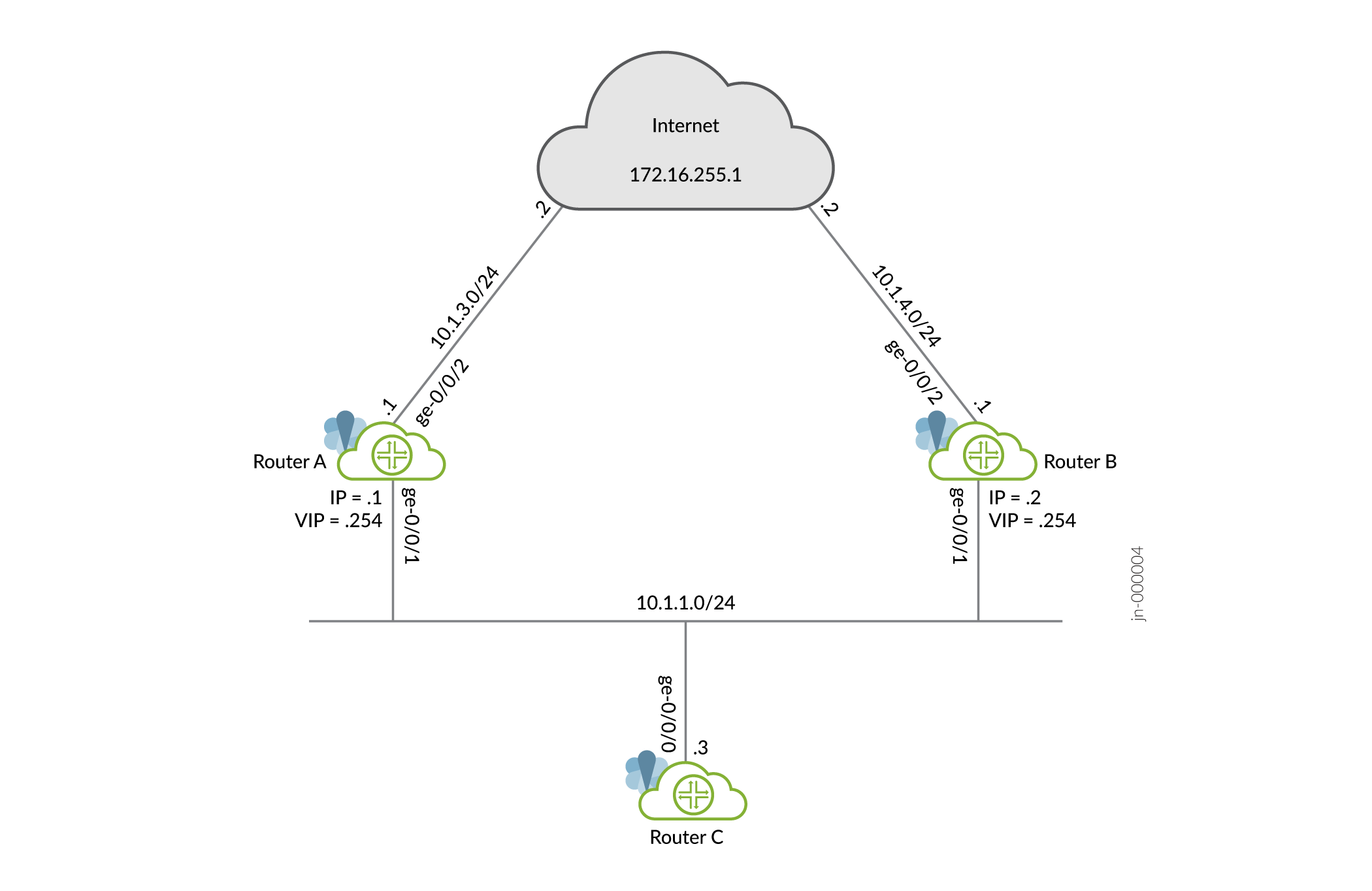
This example uses a VRRP group, which has a virtual address for IPv4. Devices on the LAN use this virtual address as their default gateway. If the primary router fails, the backup router takes over for it.
Configuring VRRP
Configuring Router A
CLI Quick Configuration
To quickly configure this example, copy the following commands, paste them
into a text file, remove any line breaks, change any details necessary to
match your network configuration, and then copy and paste the commands into
the CLI at the [edit] hierarchy level.
set interfaces ge-0/0/1 unit 0 family inet address 10.1.1.1/24 vrrp-group 1 virtual-address 10.1.1.254
set interfaces ge-0/0/1 unit 0 family inet address 10.1.1.1/24 vrrp-group 1 priority 110
set interfaces ge-0/0/1 unit 0 family inet address 10.1.1.1/24 vrrp-group 1 accept-data
set interfaces ge-0/0/1 unit 0 family inet address 10.1.1.1/24 vrrp-group 1 track interface ge-0/0/2 priority-cost 20
set interfaces ge-0/0/2 unit 0 family inet address 10.1.3.1/24
set routing-options static route 0.0.0.0/0 next-hop 10.1.3.2
Step-by-Step Procedure
To configure this example:
-
Configure the interfaces.
[edit]
user@routerA# set interfaces ge-0/0/1 unit 0 family inet address 10.1.1.1/24
user@routerA# set interfaces ge-0/0/2 unit 0 family inet address 10.1.3.1/24
-
Configure the IPv4 VRRP group identifier and the virtual IP address.
[edit interfaces ge-0/0/1 unit 0 family inet address 10.1.1.1/24]
user@routerA# set vrrp-group 1 virtual-address 10.1.1.254
-
Configure the priority for RouterA higher than RouterB to become the primary virtual router. RouterB is using the default priority of 100.
[edit interfaces ge-0/0/1 unit 0 family inet address 10.1.1.1/24]
user@routerA# set vrrp-group 1 priority 110
-
Configure
track interfaceto track whether the interface connected to the Internet is up, down, or not present to change the priority of the VRRP group.[edit interfaces ge-0/0/1 unit 0 family inet address 10.1.1.1/24] user@routerA# set vrrp-group 1 track interface ge-0/0/2 priority-cost 20
-
Configure
accept-datato enable the primary router to accept all packets destined for the virtual IP address.[edit interfaces ge-0/0/1 unit 0 family inet address 10.1.1.1/24] user@routerA# set vrrp-group 1 accept-data
-
Configure a static route for traffic to the Internet.
[edit]
user@routerA# set routing-options static route 0.0.0.0/0 next-hop 10.1.3.2
Results
From configuration mode, confirm your configuration by entering the
show interfaces and show
routing-options commands. If the output does not display the
intended configuration, repeat the instructions in this example to correct
the configuration.
[edit]
user@routerA# show interfaces
ge-0/0/1 {
    unit 0 {
        family inet {
            address 10.1.1.1/24 {
                vrrp-group 1 {
                    virtual-address 10.1.1.254;
                    priority 110;
                    accept-data;
                    track {
                        interface ge-0/0/2 {
                            priority-cost 20;
                        }
                    }
                }
            }
        }
    }
}
ge-0/0/2 {
    unit 0 {
        family inet {
            address 10.1.3.1/24;
        }
    }
}
[edit]
user@routerA# show routing-options
static {
    route 0.0.0.0/0 next-hop 10.1.3.2;
}
If you are done configuring the device, enter commit from
configuration mode.
Configuring Router B
CLI Quick Configuration
To quickly configure this example, copy the following commands, paste them
into a text file, remove any line breaks, change any details necessary to
match your network configuration, and then copy and paste the commands into
the CLI at the [edit] hierarchy level.
set interfaces ge-0/0/1 unit 0 family inet address 10.1.1.2/24 vrrp-group 1 virtual-address 10.1.1.254
set interfaces ge-0/0/1 unit 0 family inet address 10.1.1.2/24 vrrp-group 1 accept-data
set interfaces ge-0/0/2 unit 0 family inet address 10.1.4.1/24
set routing-options static route 0.0.0.0/0 next-hop 10.1.4.2
Step-by-Step Procedure
To configure this example:
-
Configure the interfaces.
[edit]
user@routerB# set interfaces ge-0/0/1 unit 0 family inet address 10.1.1.2/24
user@routerB# set interfaces ge-0/0/2 unit 0 family inet address 10.1.4.1/24
-
Configure the IPv4 VRRP group identifier and the virtual IP address.
[edit interfaces ge-0/0/1 unit 0 family inet address 10.1.1.2/24]
user@routerB# set vrrp-group 1 virtual-address 10.1.1.254
-
Configure
accept-datato enable the backup router to accept all packets destined for the virtual IP address in the event the backup router becomes primary.[edit interfaces ge-0/0/1 unit 0 family inet address 10.1.1.2/24] user@routerB# set vrrp-group 1 accept-data
-
Configure a static route for traffic to the Internet.
[edit]
user@routerB# set routing-options static route 0.0.0.0/0 next-hop 10.1.4.2
Results
From configuration mode, confirm your configuration by entering the
show interfaces and show
routing-options commands. If the output does not display the
intended configuration, repeat the instructions in this example to correct
the configuration.
[edit]
user@routerB# show interfaces
ge-0/0/1 {
    unit 0 {
        family inet {
            address 10.1.1.2/24 {
                vrrp-group 1 {
                    virtual-address 10.1.1.254;
                    accept-data;
                }
            }
        }
    }
}
ge-0/0/2 {
    unit 0 {
        family inet {
            address 10.1.4.1/24;
        }
    }
}
[edit]
user@routerB# show routing-options
static {
    route 0.0.0.0/0 next-hop 10.1.4.2;
}
If you are done configuring the device, enter commit from
configuration mode.
Configuring Router C
CLI Quick Configuration
To quickly configure this example, copy the following commands, paste them into a
text file, remove any line breaks, change any details necessary to match your
network configuration, and then copy and paste the commands into the CLI at the
[edit] hierarchy level.
set interfaces ge-0/0/0 unit 0 family inet address 10.1.1.3/24
set routing-options static route 0.0.0.0/0 next-hop 10.1.1.254
Verification
- Verifying That VRRP Is Working on Router A
- Verifying That VRRP Is Working on Router B
- Verifying Router C Reaches the Internet Transiting Router A
- Verifying Router B Becomes Primary for VRRP
Verifying That VRRP Is Working on Router A
Purpose
Verify that VRRP is active on Router A and that its role in the VRRP group is correct.
Action
Use the following commands to verify that VRRP is active on Router A, that the router is primary for group 1 and the interface connected to the Internet is being tracked.
user@routerA> show vrrp
Interface     State       Group   VR state VR Mode   Timer    Type   Address
ge-0/0/1.0    up              1   master   Active      A  0.779 lcl    10.1.1.1
                                                                vip    10.1.1.254
user@routerA> show vrrp track
Track Int   State         Speed   VRRP Int   Group   VR State      Current prio
ge-0/0/2.0  up               1g   ge-0/0/1.0     1   master                 110
Meaning
The show vrrp command displays fundamental information about
the VRRP configuration. This output shows that the VRRP group is active and
that this router has assumed the primary role. The lcl
address is the physical address of the interface and the
vip address is the virtual address shared by both
routers. The Timer value (A 0.779)
indicates the remaining time (in seconds) in which this router expects to
receive a VRRP advertisement from the other router.
Verifying That VRRP Is Working on Router B
Purpose
Verify that VRRP is active on Router B and that its role in the VRRP group is correct.
Action
Use the following command to verify that VRRP is active on Router B and that the router is backup for group 1.
user@routerB> show vrrp
Interface     State       Group   VR state VR Mode   Timer    Type   Address
ge-0/0/1.0    up              1   backup   Active      D  2.854 lcl    10.1.1.2
                                                                vip    10.1.1.254
                                                                mas    10.1.1.1
Meaning
The show vrrp command displays fundamental information about
the VRRP configuration. This output shows that the VRRP group is active and
that this router has assumed the backup role. The lcl
address is the physical address of the interface and the
vip address is the virtual address shared by both
routers. The Timer value (D 2.854)
indicates the remaining time (in seconds) in which this router expects to
receive a VRRP advertisement from the other router.
Verifying Router C Reaches the Internet Transiting Router A
Purpose
Verify connectivity to the Internet from Router C.
Action
Use the following commands to verify that Router C can reach the Internet.
user@routerC> ping 172.16.255.1 count 2
PING 172.16.255.1 (172.16.255.1): 56 data bytes
64 bytes from 172.16.255.1: icmp_seq=0 ttl=63 time=9.394 ms
64 bytes from 172.16.255.1: icmp_seq=1 ttl=63 time=30.536 ms

--- 172.16.255.1 ping statistics ---
2 packets transmitted, 2 packets received, 0% packet loss
round-trip min/avg/max/stddev = 9.394/19.965/30.536/10.571 ms
user@routerC> traceroute 172.16.255.1
traceroute to 172.16.255.1 (172.16.255.1), 30 hops max, 52 byte packets
 1  10.1.1.1  3.781 ms  37.650 ms  3.877 ms
 2  172.16.255.1  31.581 ms  31.337 ms  27.170 ms
Meaning
The ping command shows reachability to the Internet and the
traceroute command shows that Router A is being
transited.
Verifying Router B Becomes Primary for VRRP
Purpose
Verify that Router B becomes primary for VRRP when the interface between Router A and the Internet goes down.
Action
Use the following commands to verify that Router B is primary and that Router C can reach the Internet transiting Router B.
user@routerA> show vrrp track detail
Tracked interface: ge-0/0/2.0
  State: down, Speed: 1g
  Incurred priority cost: 20
  Tracking VRRP interface: ge-0/0/1.0, Group: 1
    VR State: backup
    Current priority: 90, Configured priority: 110
    Priority hold-time: disabled
user@routerB> show vrrp
Interface     State       Group   VR state VR Mode   Timer    Type   Address
ge-0/0/1.0    up              1   master   Active      A  0.079 lcl    10.1.1.2
                                                                vip    10.1.1.254
user@routerC> traceroute 172.16.255.1
traceroute to 172.16.255.1 (172.16.255.1), 30 hops max, 52 byte packets
 1  10.1.1.2  6.532 ms  3.800 ms  2.958 ms
 2  172.16.255.1  44.359 ms  16.268 ms  22.823 ms
Meaning
The show vrrp track detail command shows the tracked
interface is down on Router A, that the priority has dropped to 90, and that
Router A is now the backup. The show vrrp command shows
that Router B is now the primary for VRRP and the
traceroute command shows that Router B is now being
transited.
Configuring VRRP and VRRP for IPv6
To configure VRRP or VRRP for IPv6, include the vrrp-group or vrrp-inet6-group statement, respectively. These statements
are available at the following hierarchy levels:
[edit interfaces interface-name unit logical-unit-number family inet address address][edit logical-systems logical-system-name interfaces interface-name unit logical-unit-number family inet address address]
The VRRP and VRRP IPv6 configuration statements are as follows:
(vrrp-group | vrrp-inet6-group) group-number {
    (accept-data | no-accept-data);
    advertise-interval seconds;
    authentication-key key;
    authentication-type authentication;
    fast-interval milliseconds;
    (preempt | no-preempt) {
        hold-time seconds;
    }
    priority-number number;
    track {
        priority-hold-time;
        interface interface-name {
            priority-cost priority;
            bandwidth-threshold bits-per-second {
                priority-cost;
            }
        }
    }
    virtual-address [ addresses ];
}
You can configure VRRP IPv6 with a global unicast address.
To trace VRRP and VRRP for IPv6 operations, include the traceoptions statement at the [edit protocols vrrp] hierarchy level:
[edit protocols vrrp]
traceoptions {
    file <filename> <files number <match regular-expression <microsecond-stamp> <size size> <world-readable | no-world-readable>;
    flag flag;
    no-remote-trace;
}
When there are multiple VRRP groups, there is a few seconds
delay between the time the first gratuitous ARP is sent out and the
rest of the gratuitous ARP are sent. Configuring failover-delay compensates
for this delay. To configure the failover delay from 500 to 2000 milliseconds
for VRRP and VRRP for IPv6 operations, include the failover-delay milliseconds statement at the [edit protocols
vrrp] hierarchy level:
[edit protocols vrrp] failover-delay milliseconds;
To configure the startup period for VRRP and VRRP for IPv6 operations,
include the startup-silent-period statement at the [edit protocols vrrp] hierarchy level:
[edit protocols vrrp]
startup-silent-period seconds;
To enable VRRPv3, set the version-3 statement at
the [edit protocols vrrp] hierarchy level:
[edit protocols vrrp]
version-3;
Configuring VRRP for IPv6 (CLI Procedure)
By configuring the Virtual Router Redundancy Protocol (VRRP) on EX Series switches, you can enable hosts on a LAN to make use of redundant routing platforms on that LAN without requiring more than the static configuration of a single default route on the hosts. You can configure VRRP for IPv6 on Gigabit Ethernet, 10-Gigabit Ethernet, and logical interfaces.
To configure VRRP for IPv6:
Example: Configuring VRRP for IPv6
This example shows how to configure VRRP properties for IPv6.
Requirements
This example uses the following hardware and software components:
-
Three routers
-
Junos OS Release 11.3 or later
- This example has been recently updated and revalidated on Junos OS Release 21.1R1.
- For details on VRRP support for specific platform and Junos OS release combinations, see Feature Explorer.
Overview
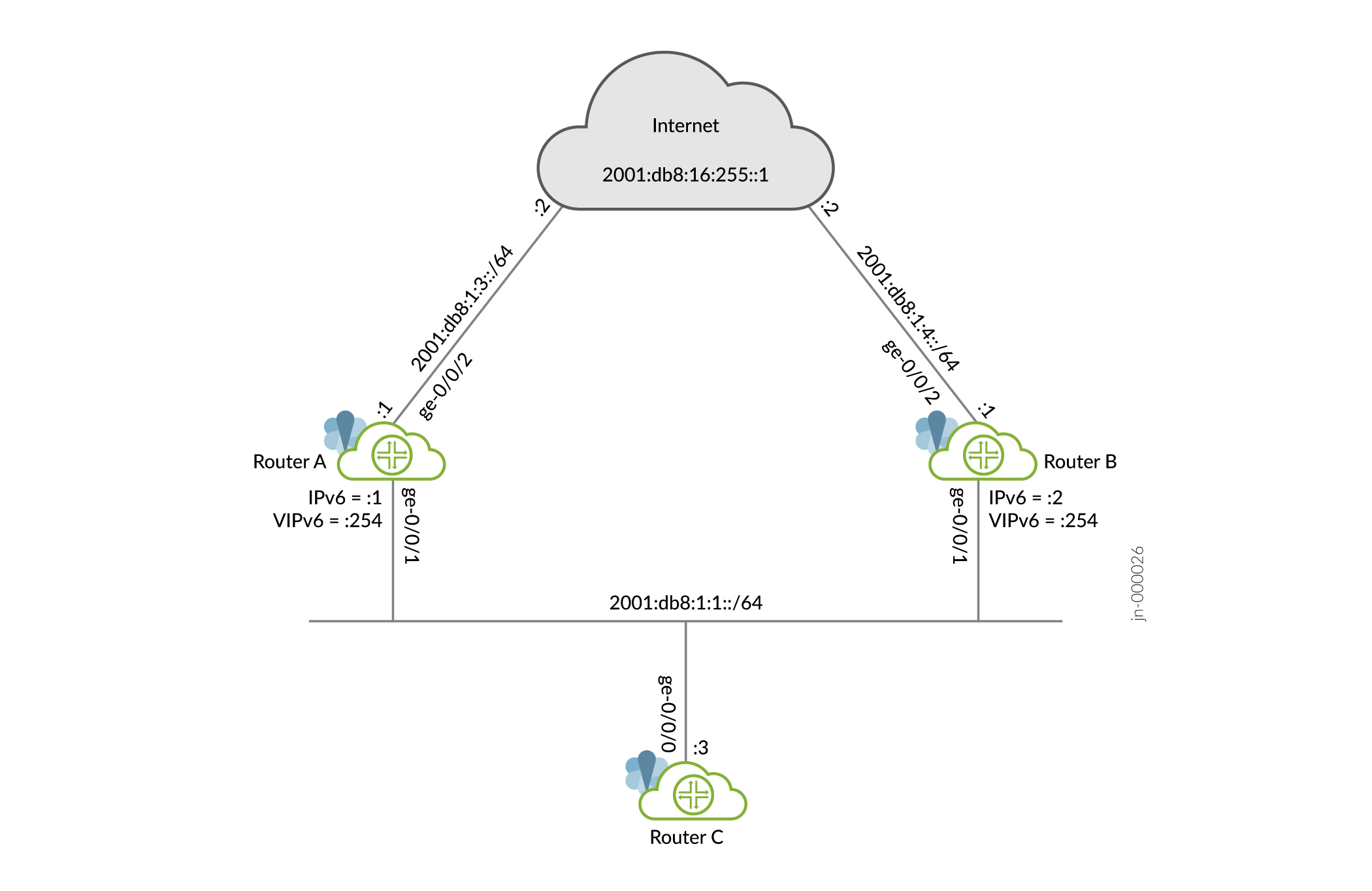
This example uses a VRRP group, which has a virtual address for IPv6. Devices on the LAN use this virtual address as their default gateway. If the primary router fails, the backup router takes over for it.
Configuring VRRP
Configuring Router A
CLI Quick Configuration
To quickly configure this example, copy the following commands, paste into a
text file, remove any line breaks, change any details necessary to match
your network configuration, and then copy and paste the commands into the
CLI at the [edit] hierarchy level.
set interfaces ge-0/0/1 unit 0 family inet6 address 2001:db8:1:1::1/64 vrrp-inet6-group 1 virtual-inet6-address 2001:db8:1:1::254
set interfaces ge-0/0/1 unit 0 family inet6 address 2001:db8:1:1::1/64 vrrp-inet6-group 1 priority 110
set interfaces ge-0/0/1 unit 0 family inet6 address 2001:db8:1:1::1/64 vrrp-inet6-group 1 accept-data
set interfaces ge-0/0/1 unit 0 family inet6 address 2001:db8:1:1::1/64 vrrp-inet6-group 1 track interface ge-0/0/2 priority-cost 20
set interfaces ge-0/0/2 unit 0 family inet6 address 2001:db8:1:3::1/64
set protocols router-advertisement interface ge-0/0/1.0 virtual-router-only
set protocols router-advertisement interface ge-0/0/1.0 prefix 2001:db8:1:1::/64
set routing-options rib inet6.0 static route 0::0/0 next-hop 2001:db8:1:3::2
Step-by-Step Procedure
To configure this example:
-
Configure the interfaces.
[edit]
user@routerA# set interfaces ge-0/0/1 unit 0 family inet6 address 2001:db8:1:1::1/64
user@routerA# set interfaces ge-0/0/2 unit 0 family inet6 address 2001:db8:1:3::1/64
-
Configure the IPv6 VRRP group identifier and the virtual IP address.
[edit interfaces ge-0/0/1 unit 0 family inet6 address 2001:db8:1:1::1/64]
user@routerA# set vrrp-inet6-group 1 virtual-inet6-address 2001:db8:1:1::254
-
Configure the priority for RouterA higher than RouterB to become the primary virtual router. RouterB is using the default priority of 100.
[edit interfaces ge-0/0/1 unit 0 family inet6 address 2001:db8:1:1::1/64]
user@routerA# set vrrp-inet6-group 1 priority 110
-
Configure
track interfaceto track whether the interface connected to the Internet is up, down, or not present to change the priority of the VRRP group.[edit interfaces ge-0/0/1 unit 0 family inet6 address 2001:db8:1:1::1/64] user@routerA# set vrrp-inet6-group 1 track interface ge-0/0/2 priority-cost 20
-
Configure
accept-datato enable the primary router to accept all packets destined for the virtual IP address.[edit interfaces ge-0/0/1 unit 0 family inet6 address 2001:db8:1:1::1/64] user@routerA# set vrrp-inet6-group 1 accept-data
-
Configure a static route for traffic to the Internet.
[edit]
user@routerA# set routing-options rib inet6.0 static route 0::0/0 next-hop 2001:db8:1:3::2
-
For VRRP for iPv6, you must configure the interface on which VRRP is configured to send IPv6 router advertisements for the VRRP group. When an interface receives an IPv6 router solicitation message, it sends an IPv6 router advertisement to all VRRP groups configured on it.
[edit protocols router-advertisement interface ge-0/0/1.0]
user@routerA# set prefix 2001:db8:1:1::/64
-
Configure router advertisements to be sent only for VRRP IPv6 groups configured on the interface if the groups are in the primary state.
[edit protocols router-advertisement interface ge-0/0/1.0]
user@routerA# set virtual-router-only
Results
From configuration mode, confirm your configuration by entering the
show interfaces, show protocols
router-advertisement and show routing-options
commands. If the output does not display the intended configuration, repeat
the instructions in this example to correct the configuration.
[edit]
user@routerA# show interfaces
ge-0/0/1 {
    unit 0 {
        family inet6 {
            address 2001:db8:1:1::1/64 {
                vrrp-inet6-group 1 {
                    virtual-inet6-address 2001:db8:1:1::254;
                    priority 110;
                    accept-data;
                    track {
                        interface ge-0/0/2 {
                            priority-cost 20;
                        }
                    }
                }
            }
        }
    }
}
ge-0/0/2 {
    unit 0 {
        family inet6 {
            address 2001:db8:1:3::1/64;
        }
    }
}
[edit]
user@routerA# show protocols router-advertisement
interface ge-0/0/1.0 {
    virtual-router-only;
    prefix 2001:db8:1:1::/64;
}
[edit]
user@routerA# show routing-options
rib inet6.0 {
    static {
        route 0::0/0 next-hop 2001:db8:1:3::2;
    }
}
If you are done configuring the device, enter commit from
configuration mode.
Configuring Router B
CLI Quick Configuration
To quickly configure this example, copy the following commands, paste them
into a text file, remove any line breaks, change any details necessary to
match your network configuration, and then copy and paste the commands into
the CLI at the [edit] hierarchy level.
set interfaces ge-0/0/1 unit 0 family inet6 address 2001:db8:1:1::2/64 vrrp-inet6-group 1 virtual-inet6-address 2001:db8:1:1::254
set interfaces ge-0/0/1 unit 0 family inet6 address 2001:db8:1:1::2/64 vrrp-inet6-group 1 priority 110
set interfaces ge-0/0/1 unit 0 family inet6 address 2001:db8:1:1::2/64 vrrp-inet6-group 1 accept-data
set protocols router-advertisement interface ge-0/0/1.0 virtual-router-only
set protocols router-advertisement interface ge-0/0/1.0 prefix 2001:db8:1:1::/64
Step-by-Step Procedure
To configure this example:
-
Configure the interfaces.
[edit]
user@routerB# set interfaces ge-0/0/1 unit 0 family inet6 address 2001:db8:1:1::2/64
user@routerB# set interfaces ge-0/0/2 unit 0 family inet6 address 2001:db8:1:4::1/64
-
Configure the IPv6 VRRP group identifier and the virtual IP address.
[edit interfaces ge-0/0/1 unit 0 family inet6 address 2001:db8:1:1::2/64]
user@routerB# set vrrp-inet6-group 1 virtual-inet6-address 2001:db8:1:1::254
-
Configure
accept-datato enable the backup router to accept all packets destined for the virtual IP address in the event the backup router becomes primary.[edit interfaces ge-0/0/1 unit 0 family inet6 address 2001:db8:1:1::2/64] user@routerB# set vrrp-inet6-group 1 accept-data
-
Configure a static route for traffic to the Internet.
[edit]
user@routerB# set routing-options rib inet6.0 static route 0::0/0 next-hop 2001:db8:1:4::2
-
Configure the interface on which VRRP is configured to send IPv6 router advertisements for the VRRP group. When an interface receives an IPv6 router solicitation message, it sends an IPv6 router advertisement to all VRRP groups configured on it.
[edit protocols router-advertisement interface ge-0/0/1.0]
user@routerB# set prefix 2001:db8:1:1::/64
-
Configure router advertisements to be sent only for VRRP IPv6 groups configured on the interface if the groups are in the primary state.
[edit protocols router-advertisement interface ge-0/0/1.0]
user@routerB# set virtual-router-only
Results
From configuration mode, confirm your configuration by entering the
show interfaces, show protocols
router-advertisement and show routing-options
commands. If the output does not display the intended configuration, repeat
the instructions in this example to correct the configuration.
[edit]
user@routerB# show interfaces
ge-0/0/1 {
    unit 0 {
        family inet6 {
            address 2001:db8:1:1::2/64 {
                vrrp-inet6-group 1 {
                    virtual-inet6-address 2001:db8:1:1::254;
                    accept-data;
                }
            }
        }
    }
}
ge-0/0/2 {
    unit 0 {
        family inet6 {
            address 2001:db8:1:4::1/64;
        }
    }
}
[edit]
user@routerB# show protocols router-advertisement
interface ge-0/0/1.0 {
    virtual-router-only;
    prefix 2001:db8:1:1::/64;
}
[edit]
user@routerB# show routing-options
rib inet6.0 {
    static {
        route 0::0/0 next-hop 2001:db8:1:4::2;
    }
}
If you are done configuring the device, enter commit from
configuration mode.
Configuring Router C
CLI Quick Configuration
To quickly configure this example, copy the following commands, paste them into a
text file, remove any line breaks, change any details necessary to match your
network configuration, and then copy and paste the commands into the CLI at the
[edit] hierarchy level.
set interfaces ge-0/0/0 unit 0 family inet6 address 2001:db8:1:1::3/64
set routing-options rib inet6.0 static route 0::0/0 next-hop 2001:db8:1:1::254
Verification
- Verifying That VRRP Is Working on Router A
- Verifying That VRRP Is Working on Router B
- Verifying Router C Reaches the Internet Transiting Router A
- Verifying Router B Becomes Primary for VRRP
Verifying That VRRP Is Working on Router A
Purpose
Verify that VRRP is active on Router A and that its role in the VRRP group is correct.
Action
Use the following commands to verify that VRRP is active on Router A, that the router is primary for group 1 and the interface connected to the Internet is being tracked.
user@routerA> show vrrp
Interface     State       Group   VR state VR Mode   Timer    Type   Address
ge-0/0/1.0    up              1   master   Active      A  0.690 lcl    2001:db8:1:1::1
                                                                vip    fe80::200:5eff:fe00:201
                                                                vip    2001:db8:1:1::254
user@routerA> show vrrp track
Track Int   State         Speed   VRRP Int   Group   VR State      Current prio
ge-0/0/2.0  up               1g   ge-0/0/1.0     1   master                 110
Meaning
The show vrrp command displays fundamental information about
the VRRP configuration. This output shows that the VRRP group is active and
that this router has assumed the primary role. The lcl
address is the physical address of the interface and the
vip address is the virtual address shared by both
routers. The Timer value (A 0.690)
indicates the remaining time (in seconds) in which this router expects to
receive a VRRP advertisement from the other router.
Verifying That VRRP Is Working on Router B
Purpose
Verify that VRRP is active on Router B and that its role in the VRRP group is correct.
Action
Use the following command to verify that VRRP is active on Router B and that the router is backup for group 1.
user@routerB> show vrrp
Interface     State       Group   VR state VR Mode   Timer    Type   Address
ge-0/0/1.0    up              1   backup   Active      D  2.947 lcl    2001:db8:1:1::2
                                                                vip    fe80::200:5eff:fe00:201
                                                                vip    2001:db8:1:1::254
                                                                mas    fe80::5668:a0ff:fe99:2d7d
Meaning
The show vrrp command displays fundamental information about
the VRRP configuration. This output shows that the VRRP group is active and
that this router has assumed the backup role. The lcl
address is the physical address of the interface and the
vip address is the virtual address shared by both
routers. The Timer value (D 2.947)
indicates the remaining time (in seconds) in which this router expects to
receive a VRRP advertisement from the other router.
Verifying Router C Reaches the Internet Transiting Router A
Purpose
Verify connectivity to the Internet from Router C.
Action
Use the following commands to verify that Router C can reach the Internet.
user@routerC> ping 2001:db8:16:255::1 count 2
PING6(56=40+8+8 bytes) 2001:db8:1:1::3 --> 2001:db8:16:255::1
16 bytes from 2001:db8:16:255::1, icmp_seq=0 hlim=63 time=12.810 ms
16 bytes from 2001:db8:16:255::1, icmp_seq=1 hlim=63 time=30.139 ms

--- 2001:db8:16:255::1 ping6 statistics ---
2 packets transmitted, 2 packets received, 0% packet loss
round-trip min/avg/max/std-dev = 12.810/21.474/30.139/8.664 ms
user@routerC> traceroute 2001:db8:16:255::1
traceroute6 to 2001:db8:16:255::1 (2001:db8:16:255::1) from 2001:db8:1:1::3, 64 hops max, 12 byte packets
 1  2001:db8:1:1::1 (2001:db8:1:1::1)  9.891 ms  32.353 ms  7.859 ms
 2  2001:db8:16:255::1 (2001:db8:16:255::1)  257.483 ms  19.877 ms  7.451 ms
Meaning
The ping command shows reachabilty to the Internet and the
traceroute command shows that Router A is being
transited.
Verifying Router B Becomes Primary for VRRP
Purpose
Verify that Router B becomes primary for VRRP when the interface between Router A and the Internet goes down.
Action
Use the following commands to verify that Router B is primary and that Router C can reach the Internet transiting Router B.
user@routerA> show vrrp track detail
Tracked interface: ge-0/0/2.0
  State: down, Speed: 1g
  Incurred priority cost: 20
  Tracking VRRP interface: ge-0/0/1.0, Group: 1
    VR State: backup
    Current priority: 90, Configured priority: 110
    Priority hold-time: disabled
user@routerB> show vrrp
Interface     State       Group   VR state VR Mode   Timer    Type   Address
ge-0/0/1.0    up              1   master   Active      A  0.119 lcl    2001:db8:1:1::2
                                                                vip    fe80::200:5eff:fe00:201
                                                                vip    2001:db8:1:1::254
user@routerC> traceroute 2001:db8:16:255::1
traceroute6 to 2001:db8:16:255::1 (2001:db8:16:255::1) from 2001:db8:1:1::3, 64 hops max, 12 byte packets
 1  2001:db8:1:1::2 (2001:db8:1:1::2)  52.945 ms  344.383 ms  29.540 ms
 2  2001:db8:16:255::1 (2001:db8:16:255::1)  46.168 ms  24.744 ms  23.867 ms
Meaning
The show vrrp track detail command shows the tracked
interface is down on Router A, that the priority has dropped to 90, and that
Router A is now the backup. The show vrrp command shows
that Router B is now the primary for VRRP and the
traceroute command shows that Router B is now being
transited.
Configuring VRRP Authentication (IPv4 Only)
VRRP (IPv4 only) protocol exchanges can be authenticated to guarantee that only trusted routing platforms participate in routing in an autonomous system (AS). By default, VRRP authentication is disabled. You can configure one of the following authentication methods. Each VRRP group must use the same method.
Simple authentication—Uses a text password included in the transmitted packet. The receiving routing platform uses an authentication key (password) to verify the packet.
Message Digest 5 (MD5) algorithm—Creates the authentication data field in the IP authentication header. This header is used to encapsulate the VRRP PDU. The receiving routing platform uses an authentication key (password) to verify the authenticity of the IP authentication header and VRRP PDU.
To enable authentication and specify an authentication
method, include the authentication-type statement:
authentication-type authentication;
authentication can be simple or md5. The authentication type must be the same for all routing platforms in the VRRP group.
You can include this statement at the following hierarchy levels:
[edit interfaces interface-name unit logical-unit-number family inet address address vrrp-group group-id][edit logical-systems logical-system-name interfaces interface-name unit logical-unit-number family inet address address vrrp-group group-id]
If you include the authentication-type statement,
you can configure a key (password) on each interface by including
the authentication-key statement:
authentication-key key;
key (the password) is an ASCII string. For simple authentication, it can be from 1 through 8 characters long. For MD5 authentication, it can be from 1 through 16 characters long. If you include spaces, enclose all characters in quotation marks (“ ”). The key must be the same for all routing platforms in the VRRP group.
You can include this statement at the following hierarchy levels:
[edit interfaces interface-name unit logical-unit-number family inet address address vrrp-group group-id][edit logical-systems logical-system-name interfaces interface-name unit logical-unit-number family inet address address vrrp-group group-id]
When VRRPv3 is enabled, the authentication-type and authentication-key statements cannot be configured
for any VRRP groups. Therefore, if authentication is required, you
need to configure alternative non-VRRP authentication mechanisms.
Configuring VRRP Preemption and Hold Time
Configuring VRRP Preemption
By default, a higher-priority VRRP backup switch preempts a lower-priority primary switch. To explicitly enable this behavior, include the following statement:
preempt;
To prohibit a higher-priority VRRP backup switch from preempting a lower-priority primary switch, include the following statement on the lower-priority switch:
no-preempt;
You can include these statements at the following hierarchy level:
[edit interfaces interface-name unit logical-unit-number family inet address address vrrp-group group-id]
Configuring the Preemption Hold Time
You can also configure a preemption hold time, which is the number of seconds a higher-priority backup router that has just started up waits before preempting the primary router. You might want to configure a hold time so that routing protocols or other Junos OS components converge before preemption occurs.
The hold time is applied only on startup. By default, the hold-time value is 0 seconds, meaning that preemption can occur immediately after the backup router starts up.
To modify the preemption hold-time value, configure the following statement:
hold-time seconds;
The hold time can be from 0 through 3600 seconds.
You can include this statement at the following hierarchy level:
[edit interfaces interface-name unit logical-unit-number family inet address vrrp-group group-id] preempt
Configuring the Advertisement Interval for the VRRP Primary Router
By default, the primary router sends VRRP advertisement packets every second to all members of the VRRP group. These packets indicate that the primary router is still operational. If the primary router fails or becomes unreachable, the backup router with the highest priority value becomes the new primary router.
You can modify the advertisement interval in seconds or in milliseconds. The interval must be the same for all routing platforms in the VRRP group.
For VRRP for IPv6, you must configure IPv6 router advertisements
for the interface on which VRRP is configured to send IPv6 router
advertisements for the VRRP group. To do so, include the interface interface-name statement at the [edit protocols
router-advertisement] hierarchy level. (For information about
this statement and guidelines, see the Junos OS Routing Protocols Library for Routing Devices.) When
an interface receives an IPv6 router solicitation message, it sends
an IPv6 router advertisement to all VRRP groups configured on it.
In the case of logical systems, IPv6 router advertisements are not
sent to VRRP groups.
The primary VRRP for an IPv6 router must respond to a
router solicitation message with the virtual IP address of the router.
However, when the interface interface-name statement is included at the [edit protocols router-advertisement] hierarchy level, the backup VRRP for an IPv6 router might send a
response before the VRRP primary responds, so that the default route
of the client is not set to the primary VRRP router’s virtual
IP address. To avoid this situation, include the virtual-router-only statement at the [edit protocols router-advertisement interface interface-name] hierarchy level. When this statement
is included, router advertisements are sent only for VRRP IPv6 groups
configured on the interface (if the groups are in the primary state).
You must include this statement on both the primary and backup VRRP
for IPv6 routers.
In an EVPN network, including the virtual-router-only statement at the [edit protocols router-advertisement interface interface-name] hierarchy level restricts the router
advertisements to be sent only for the link local virtual-gateway-address.
- Modifying the Advertisement Interval in Seconds
- Modifying the Advertisement Interval in Milliseconds
Modifying the Advertisement Interval in Seconds
To modify the time, in seconds, between the sending of
VRRP advertisement packets, include the advertise-interval statement:
advertise-interval seconds;
The interval can be from 1 through 255 seconds.
You can include this statement at the following hierarchy levels:
[edit interfaces interface-name unit logical-unit-number family inet address address vrrp-group group-id][edit logical-systems logical-system-name interfaces interface-name unit logical-unit-number family inet address address vrrp-group group-id]
When VRRPv3 is enabled, the advertise-interval statement cannot be used to configure advertisement intervals. Instead,
use the fast-interval statement to configure advertisement
intervals.
Modifying the Advertisement Interval in Milliseconds
To modify the time, in milliseconds, between the sending
of VRRP advertisement packets, include the fast-interval statement:
fast-interval milliseconds;
The interval can be from 10 through 40,950 milliseconds.
You can include this statement at the following hierarchy levels:
[edit interfaces interface-name unit logical-unit-number family (inet | inet6)
address address (vrrp-group | vrrp-inet6-group) group-id]
[edit logical-systems logical-system-name interfaces interface-name unit logical-unit-number family (inet | inet6) address address (vrrp-group | vrrp-inet6-group) group-id]
In the VRRP PDU, Junos OS sets the advertisement interval
to 0. When you configure VRRP with other vendors’ routers, the fast-interval statement works correctly only when the other
routers also have an advertisement interval set to 0 in the VRRP PDUs.
Otherwise, Junos OS interprets other routers’ settings as advertisement
timer errors.
To modify the time, in milliseconds, between the sending
of VRRP for IPv6 advertisement packets, include the inet6-advertise-interval statement:
inet6-advertise-interval ms;
The range of values is from 100 through 40,000 milliseconds (ms).
You can include this statement at the following hierarchy levels:
[edit interfaces interface-name unit logical-unit-number family inet6 address address vrrp-inet6-group group-id][edit logical-systems logical-system-name interfaces interface-name unit logical-unit-number family inet6 address address vrrp-inet6-group group-id]
When VRRPv3 is enabled, the inet6-advertise-interval statement cannot be used to configure advertisement intervals. Instead,
use the fast-interval statement to configure advertisement
intervals.
Configuring the Startup Period for VRRP Operations
To configure the startup period for VRRP operations,
include the startup-silent-period statement at the [edit protocols vrrp] hierarchy level:
[edit protocols vrrp]
startup-silent-period seconds;
During the silent startup period, the show vrrp detail command output shows a value of 0 for Master priority, and your own IP address for Master router. These values
indicate that the Primary selection is not completed yet, and these
values can be ignored.
Configuring a Backup Router to Preempt the VRRP Primary Router
By default, a higher-priority backup router preempts
a lower-priority primary router. To explicitly enable the primary
router to be preempted, include the preempt statement:
preempt;
You can include this statement at the following hierarchy levels:
[edit interfaces interface-name unit logical-unit-number family (inet | inet6)
address address (vrrp-group | vrrp-inet6-group) group-id]
[edit logical-systems logical-system-name interfaces interface-name unit logical-unit-number family (Inet | inet6) address address (vrrp-group | vrrp-inet6-group) group-id]
To prohibit a higher-priority backup router from preempting
a lower-priority primary router, include the no-preempt statement:
no-preempt;
Configuring a Backup to Accept Packets Destined for the Virtual IP Address
By default, a switch configured to be a VRRP backup but
acting as the primary does not process packets sent to the virtual
IP address—that is, packets in which the destination address
is the virtual IP address. To configure a backup switch to process
packets sent to the virtual IP address while it is acting as the primary,
include the accept-data statement on the backup:
accept-data;
You can include this statement at the following hierarchy level:
[edit interfaces interface-name unit logical-unit-number family inet address address vrrp-group] group-id
To explicitly prohibit the backup from accepting packets
destined for the virtual IP address while acting as primary, include
the no-accept-data statement:
no-accept-data;
If you include the accept-data statement, configure
the connected hosts so that they:
Process gratuitous ARP requests.
Do not use packets other than ARP replies to update their ARP cache.
This statement is disabled by default. If you enable it, your configuration does not comply with RFC 3768.
To restrict incoming IP packets to ICMP only, you must configure firewall filters to accept only ICMP packets.
Modifying the Preemption Hold-Time Value for the VRRP Primary Router
The hold time is the maximum number of seconds that can elapse before a higher-priority backup router preempts the primary router. You might want to configure a hold time so that all Junos OS components converge before preemption.
By default, the hold-time value is 0 seconds. A value of 0 means that preemption can occur immediately after the backup router comes online. Note that the hold time is counted from the time the backup router comes online. The hold time is only valid when the VRRP router is just coming online.
To modify the preemption hold-time value, include the hold-time statement:
hold-time seconds;
The hold time can be from 0 through 3600 seconds.
You can include this statement at the following hierarchy levels:
[edit interfaces interface-name unit logical-unit-number family (inet | inet6)
address address (vrrp-group | vrrp-inet6-group) group-id preempt]
[edit logical-systems logical-system-name interfaces interface-name unit logical-unit-number family (Inet | inet6) address address (vrrp-group | vrrp-inet6-group) group-id preempt]
Configuring the Asymmetric Hold Time for VRRP Routers
In Junos OS Release 9.5 and later, the asymmetric-hold-time statement at the
[edit protocols vrrp] hierarchy level enables you to configure
a VRRP primary router to switch over to the backup router immediately—that is,
without waiting for the priority hold time to expire—when a tracked interface or
route goes down or when the bandwidth of a tracked interface decreases. Such events
can cause an immediate reduction in the priority based on the configured priority
cost for the event, and trigger a primary-role election.
However, when the tracked route or interface comes up again, or when the bandwidth for a tracked interface increases, the backup (original primary) router waits for the hold time to expire before it updates the priority and initiates the switchover if the priority is higher than the priority for the VRRP primary (original backup) router.
If the asymmetric-hold-time statement is not configured,
the VRRP primary waits for the hold time to expire before it initiates
a switchover when a tracked route goes down or when the bandwidth
of a tracked interface decreases.
Example: Configuring Asymmetric Hold Time
[edit]
user@host# set protocols vrrp asymmetric-hold-time
[edit]
user@host# show protocols vrrp
asymmetric-hold-time;
Configuring Passive ARP Learning for Backup VRRP Routers
By default, the backup VRRP router drops ARP requests for the VRRP-IP to VRRP-MAC address translation. This means that the backup router does not learn the ARP (IP-to-MAC address) mappings for the hosts sending the requests. When it detects a failure of the primary router and transitions to become the new primary router, the backup router must re-learn all the entries that were present in the ARP cache of the primary router. In environments with many directly attached hosts, such as metro Ethernet environments, the number of ARP entries to learn can be high. This can cause a significant transition delay, during which the traffic transmitted to some of the hosts might be dropped.
Passive ARP learning enables the ARP cache in the backup
router to hold approximately the same contents as the ARP cache in
the primary router, thus preventing the problem of learning ARP entries
in a burst. To enable passive ARP learning, include the passive-learning statement at the [edit system arp] hierarchy level:
[edit system arp]
passive-learning;
We recommend setting passive learning on both the backup and primary VRRP routers. Doing so prevents the need to manually intervene when the primary router becomes the backup router. While a router is operating as the primary router, the passive learning configuration has no operational impact. The configuration takes effect only when the router is operating as a backup router.
For information about configuring gratuitous ARP and the ARP aging timer, see the Junos OS Administration Library for Routing Devices.
Configuring VRRP Route Tracking
Configure Routers R1 and R2 to run VRRP. Configure static routes and a policy for exporting the static routes on Router R3. The VRRP routing instances on R2 track the routes that are advertised by R3.
On Router R1
[edit interfaces]
ge-1/0/3 {
    unit 0 {
        vlan-id 1;
        family inet {
            address 200.100.50.2/24 {
                vrrp-group 0 {
                    virtual-address 200.100.50.101;
                    priority 195;
                }
            }
        }
    }
}
On Router R2
[edit interfaces]
ge-1/0/1 {
    unit 0 {
        vlan-id 1;
        family inet {
            address 200.100.50.1/24 {
                vrrp-group 0 {
                    virtual-address 200.100.50.101;
                    priority 200;
                    track {
                        route 59.0.58.153/32 routing-instance default priority-cost 5;
                        route 59.0.58.154/32 routing-instance default priority-cost 5;
                        route 59.0.58.155/32 routing-instance default priority-cost 5;
                    }
                }
            }
        }
    }
}
On Router R3
[edit]
policy-options {
    policy-statement static-policy {
        term term1 {
            then accept;
        }
    }
}
protocols {
    ospf {
        export static-policy;
        reference-bandwidth 4g;
        area 0.0.0.0 {
            interface all;
            interface fxp0.0 {
                disable;
            }
        }
    }
}
routing-options {
    static {
        route 59.0.0.153/32 next-hop 45.45.45.46;
        route 59.0.0.154/32 next-hop 45.45.45.46;
        route 59.0.0.155/32 next-hop 45.45.45.46;
    }
}
Configuring a Logical Interface to Be Tracked for a VRRP Group
VRRP can track whether a logical interface is up, down, or not present, and can also dynamically change the priority of the VRRP group based on the state of the tracked logical interface, triggering a new primary router election. VRRP can also track the operational speed of a logical interface and dynamically update the priority of the VRRP group when the speed crosses a configured threshold.
When interface tracking is enabled, you cannot configure a priority of 255 (a priority of 255 designates the primary router). For each VRRP group, you can track up to 10 logical interfaces.
To configure a logical interface to be tracked, include the following statements:
track {
    interface interface-name {
        bandwidth-threshold bits-per-second priority-cost priority;
        priority-cost priority;
    }
    priority-hold-time seconds;
}
interface et-0/0/0 {
    priority-cost 30;
}
You can include these statements at the following hierarchy levels:
[edit interfaces interface-name
                                unit logical-unit-number family inet
                                address address
                                vrrp-group group-id]
[edit interfaces interface-name unit logical-unit-number family inet6 address address vrrp-inet6-group group-id][edit logical-systems logical-system-name interfaces interface-name unit logical-unit-number family inet address address vrrp-group group-id][edit logical-systems logical-system-name interfaces interface-name unit logical-unit-number family inet6 address address vrrp-inet6-group group-id]
The interface specified is the interface to be tracked for the VRRP group. The priority hold time is the minimum length of time that must elapse between dynamic priority changes. A tracking event, such as an interface state change (up or down) or a change in bandwidth, triggers one of the following responses:
The first tracking event initiates the priority hold timer, and also initializes the pending priority based on the current priority and the priority cost. However, the current priority remains unchanged.
A tracking event or a manual configuration change that occurs while the priority hold timer is on triggers a pending priority update. However, the current priority remains unchanged.
This ensures that Junos OS does not initiate primary role elections every time a tracked interface flaps.
When the priority hold time expires, the current priority inherits the value from the pending priority, and the pending priority ceases.
If you have configured asymmetric-hold-time, VRRP does not wait for the priority
hold time to expire before initiating primary role elections if a tracked
interface fails (state changes from up to
down), or if the available bandwidth for a tracked interface
decreases.
There are
two priority-cost statements that show at this hierarchy
level. The bandwidth-threshold statement specifies a threshold
for the tracked interface. When the bandwidth of the tracked interface
drops below the configured bandwidth threshold value, the VRRP group
uses the bandwidth threshold priority cost. You can track up to five
bandwidth threshold statements for each tracked interface. Just under
the interface statement there is a priority-cost statement that gives the value to subtract from priority when the
interface is down.
The sum of the priority costs for all tracked logical interfaces must be less than or equal to the configured priority of the VRRP group. If you are tracking more than one interface, the router applies the sum of the priority costs for the tracked interfaces (at most, only one priority cost for each tracked interface) to the VRRP group priority.
Prior to Junos OS Release 15.1, an adjusted priority could not be zero. If the difference between the priority costs and the configured priority of the VRRP group was zero, the adjusted priority would become 1.
In Junos OS Release 15.1 and later, an adjusted priority can be zero.
The priority value zero (0) indicates that the current primary router has stopped participating in VRRP. Such a priority value is used to trigger one of the backup routers to quickly transition to the primary router without having to wait for the current primary to time out.
If you are tracking more than one interface, the router applies the sum of the priority costs for the tracked interfaces (at most, only one priority cost for each tracked interface) to the VRRP group priority. However, the interface priority cost and bandwidth threshold priority cost values for each VRRP group are not cumulative. The router uses only one priority cost to a tracked interface as indicated in Table 1.
Tracked Interface State |
Priority Cost Usage |
|---|---|
Down |
|
Not down; media speed below one or more bandwidth thresholds |
Priority cost of the lowest applicable bandwidth threshold |
You must configure an interface priority cost only if you have configured no bandwidth thresholds. If you have not configured an interface priority cost value, and the interface is down, the interface uses the bandwidth threshold priority cost value of the lowest bandwidth threshold.
Configuring a Route to Be Tracked for a VRRP Group
VRRP can track whether a route is reachable (that is, the route exists in the routing table of the routing instance included in the configuration) and dynamically change the priority of the VRRP group based on the reachability of the tracked route, triggering a new primary router election.
To configure a route to be tracked, include the following statements:
track {
    priority-hold-time seconds;
    route prefix/prefix-length routing-instance instance-name priority-cost priority;
}
You can include these statements at the following hierarchy levels:
[edit interfaces interface-name
                                unit logical-unit-number family inet
                                address address
                                vrrp-group group-id]
[edit interfaces interface-name unit logical-unit-number family inet6 address address vrrp-inet6-group group-id][edit logical-systems logical-system-name interfaces interface-name unit logical-unit-number family inet address address vrrp-group group-id][edit logical-systems logical-system-name interfaces interface-name unit logical-unit-number family inet6 address address vrrp-inet6-group group-id]
The route prefix specified is the route to be tracked for the VRRP group. The priority hold time is the minimum length of time that must elapse between dynamic priority changes. A route tracking event, such as adding a route to or removing a route from the routing table, might trigger one or more of the following:
The first tracking event initiates the priority hold timer, and also initializes the pending priority based on the current priority and the priority cost. However, the current priority remains unchanged.
A tracking event or a manual configuration change that occurs while the priority hold timer is on triggers a pending priority update. However, the current priority remains unchanged.
When the priority hold time expires, the current priority inherits the value from the pending priority, and the pending priority ceases.
This ensures that Junos OS does not initiate primary role elections every time a tracked route flaps.
If you have configured asymmetric-hold-time, VRRP does not wait for the priority
hold time to expire before initiating primary role elections if a tracked route
is removed from the routing table.
The routing instance is the routing instance in which the route
is to be tracked. If the route is in the default, or global, routing
instance, specify the instance name as default.
Tracking a route that belongs to a routing instance from a different logical system is not supported.
The priority cost is the value to be subtracted from the configured VRRP priority when the tracked route goes down, forcing a new primary router election. The value can be from 1 through 254.
The sum of the priority costs for all tracked routes must be less than or equal to the configured priority of the VRRP group. If you are tracking more than one route, the router applies the sum of the priority costs for the tracked routes (at most, only one priority cost for each tracked route) to the VRRP group priority.
Prior to Junos OS Release 15.1, an adjusted priority could not be zero. If the difference between the priority costs and the configured priority of the VRRP group was zero, the adjusted priority would become 1.
In Junos OS Release 15.1 and later, an adjusted priority can be zero.
The priority value zero (0) indicates that the current primary router has stopped participating in VRRP. Such a priority value is used to trigger one of the backup routers to quickly transition to the primary router without having to wait for the current primary to time out.
Example: Configuring Multiple VRRP Owner Groups
These examples show how to configure multiple virtual router redundancy protocol (VRRP) IPv4 and IPv6 owner groups.
Requirements
This example uses the following hardware and software components:
A EX-Series, M-Series, MX-Series, or T-Series router.
Junos OS release 12.3 or later
Overview
Multiple VRRP owner groups allows users to reuse interface address identifiers (IFAs) as virtual IP addresses (VIPs). You can configure multiple IPv4 owner groups, multiple IPv6 owner groups, or a mix of IPv4 and IPv6 owner groups.
Configuration
- CLI Quick Configuration
- Configuring multiple IPv4 owner groups
- Configuring multiple IPv6 owner groups
- Configuring multiple IPv4 and IPv6 owner groups
- Results
CLI Quick Configuration
To quickly configure this section of the example,
copy the following commands, paste them into a text file, remove any
line breaks, change any details necessary to match your network configuration,
and then copy and paste the commands into the CLI at the [edit] hierarchy level.
Multiple IPv4 owner groups
edit interfaces ge-1/0/0 unit 0 family inet
set address 10.0.0.2/24 vrrp-group 2 virtual-address 10.0.0.4 accept-data
set address 20.0.0.2/24 vrrp-group 3 virtual-address 20.0.0.2 priority 255
set address 30.0.0.2/24 vrrp-group 4 virtual-address 30.0.0.2 priority 255
Multiple IPv6 owner groups
edit interfaces ge-1/0/0 unit 0 family inet6
set address 2001:4818:f000:20::1/64 vrrp-inet6-group 1 virtual-inet6-address 2001:4818:f000:20::1
set address 2001:4818:f000:20::1/64 vrrp-inet6-group 1 virtual-link-local-address fe80:4818:f000:20::1
set address 2001:4818:f000:20::1/64 vrrp-inet6-group 1 priority 255
set address fe80:4818:f000:13::2/64
set address 2001:1000:f000:20::1/64 vrrp-inet6-group 2 virtual-inet6-address 2001:1000:f000:20::1
set address 2001:1000:f000:20::1/64 vrrp-inet6-group 2 virtual-link-local-address fe80:1000:f000:20::1
set address 2001:1000:f000:20::1/64 vrrp-inet6-group 2 priority 255
set address 2001:2000:f000:20::1/64 vrrp-inet6-group 3 virtual-inet6-address 2001:2000:f000:20::2
set address 2001:2000:f000:20::1/64 vrrp-inet6-group 3 virtual-link-local-address fe80:2000:f000:20::2
set address 2001:2000:f000:20::1/64 vrrp-inet6-group 3 priority 250
Multiple IPv4 and IPv6 owner groups
edit interfaces ge-1/0/0 unit 0
set family inet address 10.0.0.1/24 vrrp-group 5 virtual-address 10.0.0.1
set family inet address 10.0.0.1/24 vrrp-group 5 priority 255
set family inet6 address 2001:4818:f000:20::1/64 vrrp-inet6-group 1 virtual-inet6-address 2001:4818:f000:20::1
set family inet6 address 2001:4818:f000:20::1/64 vrrp-inet6-group 1 virtual-link-local-address fe80:4818:f000:20::1
set family inet6 address 2001:4818:f000:20::1/64 vrrp-inet6-group 1 priority 255
set family inet6 address 2001:1000:f000:20::1/64 vrrp-inet6-group 2 virtual-inet6-address 2001:1000:f000:20::1
set family inet6 address 2001:1000:f000:20::1/64 vrrp-inet6-group 2 virtual-link-local-address fe80:1000:f000:20::1
set family inet6 address 2001:1000:f000:20::1/64 vrrp-inet6-group 2 priority 255
set family inet6 address 2001:2000:f000:20::1/64 vrrp-inet6-group 3 virtual-inet6-address 2001:2000:f000:20::2
set family inet6 address 2001:2000:f000:20::1/64 vrrp-inet6-group 3 virtual-link-local-address fe80:2000:f000:20::2
set family inet6 address 2001:2000:f000:20::1/64 vrrp-inet6-group 3 priority 250
Configuring multiple IPv4 owner groups
Step-by-Step Procedure
To configure multiple IPv4 owner groups:
Create an IPv4 interface on the device
[edit]
user@host# edit interfaces ge-1/0/0 unit 0 family inet
Configure the first IPv4 owner group
[edit interfaces ge-1/0/0 unit 0 family inet]
user@host# set address 10.0.0.2/24 vrrp-group 2 virtual-address 10.0.0.4 accept-data
Configure the second IPv4 owner group
[edit interfaces ge-1/0/0 unit 0 family inet]
user@host# set address 20.0.0.2/24 vrrp-group 3 virtual-address 20.0.0.2 priority 255
Configure the third IPv4 owner group
[edit interfaces ge-1/0/0 unit 0 family inet]
user@host# set address 30.0.0.2/24 vrrp-group 4 virtual-address 30.0.0.2 priority 255
Configuring multiple IPv6 owner groups
Step-by-Step Procedure
To configure multiple IPv6 owner groups:
Create an IPv6 interface on the device
[edit]
user@host# edit interfaces ge-1/0/0 unit 0 family inet6
Configure the inet6 address for the first IPv6 owner group
[edit interfaces ge-1/0/0 unit 0 family inet6]
user@host# set address 2001:4818:f000:20::1/64 vrrp-inet6-group 1 virtual-inet6-address 2001:4818:f000:20::1
-
[edit interfaces ge-1/0/0 unit 0 family inet6]
user@host# set address 2001:4818:f000:20::1/64 vrrp-inet6-group 1 virtual-link-local-address fe80:4818:f000:20::1
-
[edit interfaces ge-1/0/0 unit 0 family inet6]
user@host# set address 2001:4818:f000:20::1/64 vrrp-inet6-group 1 priority 255
-
[edit interfaces ge-1/0/0 unit 0 family inet6]
user@host# set family inet6 address 2001:1000:f000:20::1/64 vrrp-inet6-group 2 virtual-inet6-address 2001:1000:f000:20::1
-
[edit interfaces ge-1/0/0 unit 0 family inet6]
user@host# set family inet6 address 2001:1000:f000:20::1/64 vrrp-inet6-group 2 virtual-link-local-address fe80:1000:f000:20::1
-
[edit interfaces ge-1/0/0 unit 0 family inet6]
user@host# set family inet6 address 2001:1000:f000:20::1/64 vrrp-inet6-group 2 priority 255
-
[edit interfaces ge-1/0/0 unit 0 family inet6]
user@host# set family inet6 address 2001:2000:f000:20::1/64 vrrp-inet6-group 3 virtual-inet6-address 2001:2000:f000:20::2
-
[edit interfaces ge-1/0/0 unit 0 family inet6]
user@host# set family inet6 address 2001:2000:f000:20::1/64 vrrp-inet6-group 3 virtual-link-local-address fe80:2000:f000:20::2
-
[edit interfaces ge-1/0/0 unit 0 family inet6]
user@host# set address 2001:2000:f000:20::1/64 vrrp-inet6-group 3 priority 250
Configuring multiple IPv4 and IPv6 owner groups
Step-by-Step Procedure
To configure multiple IPv4 and IPv6 owner groups:
Create an interface on the device
[edit]
user@host# edit interfaces ge-1/0/0 unit 0
Configure the family inet address and virtual address for the IPv4 owner group
[edit interfaces ge-1/0/0 unit 0]
user@host# set family inet address 10.0.0.1/24 vrrp-group 5 virtual-address 10.0.0.1
Set the priority of the IPv4 owner group to 255
[edit interfaces ge-1/0/0 unit 0]
set family inet address 10.0.0.1/24 vrrp-group 5 priority 255
Configure the inet6 address for the first IPv6 owner group
[edit interfaces ge-1/0/0 unit 0]
set family inet6 address 2001:4818:f000:20::1/64 vrrp-inet6-group 1 virtual-inet6-address 2001:4818:f000:20::1
Set the virtual link local address for the first IPv6 owner group
[edit interfaces ge-1/0/0 unit 0]
set family inet6 address 2001:4818:f000:20::1/64 vrrp-inet6-group 1 virtual-link-local-address fe80:4818:f000:20::1
Set the first IPv6 owner group’s priority to 255
[edit interfaces ge-1/0/0 unit 0]
set family inet6 address 2001:4818:f000:20::1/64 vrrp-inet6-group 1 priority 255
Configure the inet6 address for the second IPv6 owner group
[edit interfaces ge-1/0/0 unit 0]
set family inet6 address 2001:1000:f000:20::1/64 vrrp-inet6-group 2 virtual-inet6-address 2001:1000:f000:20::1
Set the virtual link local address for the second IPv6 owner group
[edit interfaces ge-1/0/0 unit 0]
set family inet6 address 2001:1000:f000:20::1/64 vrrp-inet6-group 2 virtual-link-local-address fe80:1000:f000:20::1
Set the second IPv6 owner group’s priority to 255
[edit interfaces ge-1/0/0 unit 0]
set family inet6 address 2001:1000:f000:20::1/64 vrrp-inet6-group 2 priority 255
Configure the inet6 address for the third IPv6 owner group
[edit interfaces ge-1/0/0 unit 0]
set family inet6 address 2001:2000:f000:20::1/64 vrrp-inet6-group 3 virtual-inet6-address 2001:2000:f000:20::2
Set the virtual link local address for the third IPv6 owner group
[edit interfaces ge-1/0/0 unit 0]
set family inet6 address 2001:2000:f000:20::1/64 vrrp-inet6-group 3 virtual-link-local-address fe80:2000:f000:20::2
Set the third IPv6 owner group’s priority to 250
[edit interfaces ge-1/0/0 unit 0]
set family inet6 address 2001:2000:f000:20::1/64 vrrp-inet6-group 3 priority 250
Results
Multiple IPv4 owner groups
[edit interfaces]
ge-1/0/0
    unit 0 {
        family inet {
            address 10.0.0.2/24 {
                vrrp-group 2 {
                    virtual-address 10.0.0.4;
                    accept-data;
                }
            }
            address 20.0.0.2/24 {
                vrrp-group 3 {
                    virtual-address 20.0.0.2;
                    priority 255;
                }
            }
            address 30.0.0.2/24 {
                vrrp-group 4 {
                    virtual-address 30.0.0.2;
                    priority 255;
                }
            }
        }
    }
Multiple IPv6 owner groups
[edit interfaces]
ge-1/0/0
    unit 0 {
        family inet6 {
            address 2001:4818:f000:20::1/64 {
                vrrp-inet6-group 1 {
                    virtual-inet6-address 2001:4818:f000:20::1;
                    virtual-link-local-address fe80:4818:f000:20::1;
                    priority 255;
                }
            }
            address fe80:4818:f000:13::2/64;
            address 2001:1000:f000:20::1/64 {
                vrrp-inet6-group 2 {
                    virtual-inet6-address 2001:1000:f000:20::1;
                    virtual-link-local-address fe80:1000:f000:20::1;
                    priority 255;
                }
            }
            address 2001:2000:f000:20::1/64 {
                vrrp-inet6-group 3 {
                    virtual-inet6-address 2001:2000:f000:20::2;
                    virtual-link-local-address fe80:2000:f000:20::2;
                    priority 250;
                }
            }
        }
    }
Multiple IPv4 and IPv6 owner groups
[edit interfaces]
ge-1/0/0
    unit 0 {
        family inet {
            address 10.0.0.1/24 {
                vrrp-group 5 {
                    virtual-address 10.0.0.1;
                    priority 255;
                }
            }
        }
        family inet6 {
            address 2001:4818:f000:20::1/64 {
                vrrp-inet6-group 1 {
                    virtual-inet6-address 2001:4818:f000:20::1;
                    virtual-link-local-address fe80:4818:f000:20::1;
                    priority 255;
                }
            }
            address 2001:1000:f000:20::1/64 {
                vrrp-inet6-group 2 {
                    virtual-inet6-address 2001:1000:f000:20::1;
                    virtual-link-local-address fe80:1000:f000:20::1;
                    priority 255;
                }
            }
            address 2001:2000:f000:20::1/64 {
                vrrp-inet6-group 3 {
                    virtual-inet6-address 2001:2000:f000:20::2;
                    virtual-link-local-address fe80:2000:f000:20::2;
                    priority 250;
                }
            }
        }
    }
Verification
To verify the configuration, run the show
interfaces ge-1/0/0 command, or use whichever name you assigned
to the interface.
Configuring Inheritance for a VRRP Group
Junos OS enables you to configure VRRP groups on the various subnets of a VLAN to inherit the state and configuration of one of the groups, which is known as the active VRRP group. When the vrrp-inherit-from configuration statement is included in the configuration, only the active VRRP group, from which the other VRRP groups are inheriting the state, sends out frequent VRRP advertisements, and processes incoming VRRP advertisements. The groups that are inheriting the state do not process any incoming VRRP advertisement because the state is always inherited from the active VRRP group. However, the groups that are inheriting the state do send out VRRP advertisements once every 2 to 3 minutes to facilitate MAC address learning on the switches placed between the VRRP routers.
If the vrrp-inherit-from statement is not configured, each of the VRRP primary groups in the various subnets on the VLAN sends out separate VRRP advertisements and adds to the traffic on the VLAN.
To configure inheritance for a VRRP group, include the vrrp-inherit-from statement at the [edit interfaces interface-name unit logical-unit-number family inet address address vrrp-group group-id] hierarchy level.
[edit interfaces interface-name unit logical-unit-number family inet address address vrrp-group group-id]
vrrp-inherit-from active-group group-index;
vrrp-inherit-from active-interface active-interface-name;
When you configure a group to inherit a state from another group, the inheriting groups and the active group must be on the same physical interface and logical system. However, the groups do not need to necessarily be on the same routing instance (as was in Junos OS releases earlier than 9.6), VLAN, or logical interface.
When you include the vrrp-inherit-from statement for a VRRP group, the VRRP group inherits the following parameters from the active group:
advertise-interval
authentication-key
authentication-type
fast-interval
preempt | no-preempt
priority
track interfaces
track route
However, you can configure the accept-data | no-accept-data statement for the group to specify whether the interface should accept packets destined for the virtual IP address.
Configuring an Interface to Accept All Packets Destined for the Virtual IP Address of a VRRP Group
In VRRP implementations where the router acting as the
primary router is not the IP address owner—the IP address owner
is the router that has the interface whose actual IP address is used
as the virtual router’s IP address (virtual IP address)—
the primary router accepts only the ARP packets from the packets that
are sent to the virtual IP address. Junos OS enables you to override
this limitation with the help of the accept-data configuration.
When the accept-data statement is included in the configuration,
the primary router accepts all packets sent to the virtual IP address
even when the primary router is not the IP address owner.
If the primary router is the IP address owner or has its priority set to 255, the primary router, by default, accepts all packets addressed to the virtual IP address. In such cases, the accept-data configuration is not required.
To configure an interface to accept all packets sent to the
virtual IP address, include the accept-data statement:
accept-data;
You can include this statement at the following hierarchy levels:
[edit interfaces interface-name unit logical-unit-number family (inet | inet6)
address address (vrrp-group | vrrp-inet6-group) group-id]
[edit logical-systems logical-system-name interfaces interface-name unit logical-unit-number family (Inet | inet6) address address (vrrp-group | vrrp-inet6-group) group-id]
To prevent a primary router that is the IP address owner
or has its priority set to 255 from accepting packets other than the
ARP packets addressed to the virtual IP address, include the no-accept-data statement:
no-accept-data;
If you want to restrict the incoming IP packets to ICMP packets only, you must configure firewall filters to accept only ICMP packets.
If you include the
accept-datastatement, your routing platform configuration does not comply with RFC 3768 (see section 6.4.3 of RFC 3768, Virtual Router Redundancy Protocol (VRRP).
Configuring the Silent Period to Avoid Alarms Due to Delay in Receiving VRRP Advertisement Packets
The silent period starts when the interface state is changed from down to up. During this period, the Primary Down Event is ignored. Configure the silent period interval to avoid alarms caused by the delay or interruption of the incoming VRRP advertisement packets during the interface startup phase.
To configure the silent period interval that the Primary
Down Event timer ignores, include the startup-silent-period statement at the [edit protocols vrrp] hierarchy level:
[edit protocols vrrp]
startup-silent-period seconds;
During the silent startup period, the show vrrp detail command output shows a value of 0 for Master priority and your IP address for Master router. These values indicate
that the Primary selection is not completed yet, and these values
can be ignored.
When you have configured startup-silent-period, the Primary Down Event is ignored until the startup-silent-period expires.
For example, configure a VRRP group, vrrp-group1, with an advertise interval of 1 second, startup silent period of 10 seconds, and an interface interface1 with a priority less than 255.
When interface1 transitions from down to up:
The vrrp-group1 group moves to the backup state, and starts the Primary Down Event timer (3 seconds; three times the value of the advertise interval, which is 1 second in this case).
If no VRRP PDU is received during the 3-second period, the startup-silent-period (10 seconds in this case) is checked, and if the startup silent period has not expired, the Primary Down Event timer is restarted. This is repeated until the startup-silent-period expires. In this example, the Primary Down Event timer runs four times (12 seconds) by the time the 10-second startup silent period expires.
If no VRRP PDU is received by the end of the fourth 3-second cycle, vrrp-group1 takes over the primary role.
Enabling the Distributed Periodic Packet Management Process for VRRP
Typically, VRRP advertisements are sent by the VRRP process (vrrpd) on the primary VRRP router at regular intervals to let other members of the group know that the VRRP primary router is operational.
When the vrrpd process is busy and does not send VRRP advertisements, the backup VRRP routers might assume that the primary router is down and take over as the primary router, causing unnecessary flaps. This takeover might occur even though the original primary router is still active and available and might resume sending advertisements after the traffic has decreased. To address this problem and to reduce the load on the vrrpd process, Junos OS uses the periodic packet management process (ppmd) to send VRRP advertisements on behalf of the vrrpd process. However, you can further delegate the job of sending VRRP advertisements to the distributed ppmd process that resides on the Packet Forwarding Engine.
The ability to delegate the sending of VRRP advertisements to the distributed ppmd process ensures that the VRRP advertisements are sent even when the ppmd process—which is now responsible for sending VRRP advertisements—is busy. Such delegation prevents the possibility of false alarms when the ppmd process is busy. The ability to delegate the sending of VRRP advertisements to distributed ppmd also adds to scalability because the load is shared across multiple ppmd instances and is not concentrated on any single unit.
CPU-intensive VRRP advertisements, such as advertisements with MD5 authentication, continue to be processed by the VRRP process on the Routing Engine even when distributed ppmd is enabled.
VRRP is supported by graceful Routing Engine switchover only in the case that PPM delegation is enabled (the default).
Aggregated Ethernet and integrated routing and bridging (IRB) delegation is supported only for MPC line cards. Routing devices with inbuilt MPCs such as the MX104 and below do not support this feature.
To configure the distributed ppmd process to send VRRP
advertisements, include the delegate-processing statement
at the [edit protocols vrrp] hierarchy level:
[edit protocols vrrp]
delegate-processing;
To configure the distributed ppmd process to send VRRP
advertisements over aggregated Ethernet and IRB interfaces, include
the delegate-processing ae-irb statement at the [edit
protocols vrrp] hierarchy level:
[edit protocols vrrp] delegate-processing ae-irb;
Improving the Convergence Time for VRRP
You can enable faster convergence time for the configured Virtual Router Redundancy Protocol (VRRP), thereby reducing the traffic restoration time to less than 1 second. To improve the convergence time for the VRRP, perform the following tasks:
Configure the distributed periodic packet management process—When the VRRP process is busy and does not send VRRP advertisements, the backup VRRP routers might assume that the primary router is down and take over as the primary router, causing unnecessary flaps. To address this problem and to reduce the load on the VRRP process, Junos OS uses the distributed periodic packet management (PPM) process to send VRRP advertisements on behalf of the VRRP process.
To configure the distributed PPM process, include the
delegate-processingstatement at the[edit protocols vrrp]hierarchy level.Disable the skew timer—The skew timer in VRRP is used to ensure that two backup routers do not switch to the primary state at the same time in case of a failover situation. When there is only one primary router and one backup router in the network deployment, you can disable the skew timer, thereby reducing the time required to transition to the primary state.
To disable the skew timer, include the
skew-timer-disablestatement at the[edit protocols vrrp]hierarchy level.Configure the number of fast advertisements that can be missed by a backup router before it starts transitioning to the master state—The backup router waits until a certain number of advertisement packets are lost after which it transitions to the primary state. This waiting time can be fatal in scenarios such as router failure or link failure. To avoid such a situation and to enable faster convergence time, in Junos OS Release 12.2 and later, you can configure a fast advertisement interval value that specifies the number of fast advertisements that can be missed by a backup router before it starts transitioning to the primary state.
To configure the fast advertisement interval, include the
global-advertisements-thresholdstatement at the[edit protocols vrrp]hierarchy level.Configure inheritance of VRRP groups—Junos OS enables you to configure VRRP groups on the various subnets of a virtual LAN (VLAN) to inherit the state and configuration of one of the groups, which is known as the active VRRP group. When the
vrrp-inherit-fromstatement is included in the configuration, only the active VRRP group, from which the other VRRP groups inherit the state, sends out frequent VRRP advertisements and processes incoming VRRP advertisements. Use inherit groups for scaled configurations. For example, if you have 1000 VRRP groups with an advertisement interval of 100 ms, then use inherit groups.To configure inheritance for a VRRP group, include the
vrrp-inherit-fromstatement at the[edit interfaces interface-name unit logical-unit-number family inet address address vrrp-group group-id]hierarchy level.-
Disable duplicate address detection for IPv6 interfaces—Starting with Junos OS Release 15.1, duplicate address detection is a feature of the Neighbor Discovery Protocol for IPv6. Duplicate address detection is enabled by default and determines whether an address is already in use by another node. When detection address detection is enabled, convergence time is high after an IPv6 interface that has been configured for VRRP tracking comes up. To disable duplicate address detection, include the
ipv6-duplicate-addr-detection-transmits 0statement at the[edit system internet-options]hierarchy level. To disable duplicate address detection only for a specific interface, include thedad-disablestatement at the[edit interfaces interface-name unit logical-unit-number family inet6]hierarchy level.
Inheritance of VRRP groups is supported with all types of interfaces. Other measures to reduce convergence time, such as VRRP distribution, disabling skew timer, and reducing advertisement threshold.
Compared to other routers, the convergence time and the traffic restoration time are less for MX Series routers with MPCs.
Reduction in convergence time is applicable for all types of configurations at the physical interface but the convergence time might not be less than 1 second for all the configurations. The convergence time depends on the number of groups that are transitioning from the backup to the primary state and the interval at which these groups are transitioning.
Configuring VRRP to Improve Convergence Time
You can enable faster convergence time for the configured Virtual Router Redundancy Protocol (VRRP), thereby reducing the traffic restoration time to less than 1 second. To improve the convergence time for VRRP, perform the following tasks.
Before you begin, configure VRRP. See Configuring VRRP.
Inheritance of VRRP groups is supported with all types of interfaces. Other measures to reduce convergence time, such as VRRP distribution, disabling skew timer, and reducing advertisement threshold, are not applicable when VRRP is configured over integrated routing and bridging (IRB) interfaces, aggregated Ethernet interfaces, and multichassis link aggregation group (MC-LAG) interfaces.
Compared to other routers, the convergence time and the traffic restoration time are less for MX Series routers with MPCs.
Reduction in convergence time is applicable for all types of configurations at the physical interface, but the convergence time might not be less than 1 second for all the configurations. The convergence time depends on the number of groups that are transitioning from the backup to the primary state and the interval at which these groups are transitioning.
Tracing VRRP Operations
To trace VRRP operations, include the traceoptions statement at the [edit protocols vrrp] hierarchy level.
By default, VRRP logs the error, data carrier detect (DCD) configuration, and routing socket events in a file in the /var/log directory. By default, this file is named /var/log/vrrpd. The default file size is 1 megabyte (MB), and three files are created before the first one gets overwritten.
To change the configuration of the logging file, include
the traceoptions statement at the [edit protocols
vrrp] hierarchy level:
[edit protocols vrrp] traceoptions { file filename <files number> <match regular-expression> <microsecond-stamp> <size size> <world-readable | no-world-readable>; flag flag; no-remote-trace; } flag flag;
You can specify the following VRRP tracing flags:
all—Trace all VRRP operations.
database—Trace all database changes.
general—Trace all general events.
interfaces—Trace all interface changes.
normal—Trace all normal events.
packets—Trace all packets sent and received.
state—Trace all state transitions.
timer—Trace all timer events.
Example: Configuring VRRP for Load Sharing
If you do not want to dedicate a switch to be a VRRP backup (and therefore leave it idle unless the primary fails), you can create a load-sharing configuration in which each participating switch simultaneously acts as a primary and a backup.
One reason to use a load-sharing (active-active) configuration is that you are more likely to actively monitor and maintain both switches and notice if a problem occurs on either of them. If you use a configuration in which one switch is only a backup (an active-backup configuration), you might be less likely to pay attention to the backup switch while it is idle. In the worst case, this could lead to the backup switch developing an undetected problem and not being able to perform adequately when a failover occurs.
Requirements
This example uses the following hardware and software components:
-
Two switches
-
Junos OS Release 11.3 or later
-
Static routing or a dynamic routing protocol enabled on both switches.
Overview and Topology
This example uses two VRRP groups, each of which has its own virtual IP address. Devices on the LAN use one of these virtual IP addresses as their default gateway. If one of the switches fails, the other switch takes over for it. In the topology shown in Figure 1, for example, Switch A is the primary for VRRP group 100. If Switch A fails, Switch B takes over and forwards traffic that the end devices send to the default gateway address 10.1.1.1.
This example shows a simple configuration to illustrate the basic steps for configuring two switches running VRRP to back each other up.Table 2 lists VRRP settings for each switch.
Topology
| Switch A | Switch B |
|---|---|
|
VRRP Group 100:
|
VRRP Group 100:
|
|
VRRP Group 200:
|
VRRP Group 200:
|
In addition to configuring the two switches as shown, you must configure your end devices so that some of them use one of the virtual IP addresses as their default gateway and the remaining end devices use the other virtual IP address as their default gateway.
Note that if a failover occurs, the remaining switch might be unable to handle all of the traffic, depending on the demand.
Configuring VRRP on Both Switches
Procedure
CLI Quick Configuration
Enter the following on Switch A:
[edit]
set interfaces xe-0/0/0 unit 0 family inet address 10.1.1.251/24 vrrp-group 100 virtual-address 10.1.1.1
set interfaces xe-0/0/0 unit 0 family inet address 10.1.1.251/24 vrrp-group 100 priority 250
set interfaces xe-0/0/0 unit 0 family inet address 10.1.1.251/24 vrrp-group 200 virtual-address 10.1.1.2
set interfaces xe-0/0/0 unit 0 family inet address 10.1.1.251/24 vrrp-group 200 priority 200
Enter the following on Switch B:
[edit]
set interfaces xe-0/0/0 unit 0 family inet address 10.1.1.252/24 vrrp-group 100 virtual-address 10.1.1.1
set interfaces xe-0/0/0 unit 0 family inet address 10.1.1.252/24 vrrp-group 100 priority 200
set interfaces xe-0/0/0 unit 0 family inet address 10.1.1.252/24 vrrp-group 200 virtual-address 10.1.1.2
set interfaces xe-0/0/0 unit 0 family inet address 10.1.1.252/24 vrrp-group 200 priority 250
Step-by-Step Procedure
Configure the VRRP groups and priorities on Switch A:
-
Create VRRP group 100 on Switch A and configure the virtual IP address for the group:
[edit]
user@switch# set interfaces xe-0/0/0 unit 0 family inet address 10.1.1.252/24 vrrp-group 100 virtual-address 10.1.1.1
-
Assign the VRRP priority for this interface in this group:
[edit]
user@switch# set interfaces xe-0/0/0 unit 0 family inet address 10.1.1.251/24 vrrp-group 100 priority 250
-
Create VRRP group 200 on Switch A and configure the virtual IP address for the group:
[edit]
user@switch# set interfaces xe-0/0/0 unit 0 family inet address 10.1.1.251/24 vrrp-group 200 virtual-address 10.1.1.2
-
Assign the VRRP priority for this interface in this group:
[edit]
user@switch# set interfaces xe-0/0/0 unit 0 family inet address 10.1.1.251/24 vrrp-group 200 priority 200
Step-by-Step Procedure
Configure the VRRP groups and priorities on Switch B:
-
Create VRRP group 100 on Switch B and configure the virtual IP address for the group:
[edit]
user@switch# set interfaces xe-0/0/0 unit 0 family inet address 10.1.1.252/24 vrrp-group 100 virtual-address 10.1.1.1
-
Assign the VRRP priority for this interface in this group:
[edit]
user@switch# set interfaces xe-0/0/0 unit 0 family inet address 10.1.1.252/24 vrrp-group 100 priority 200
Switch A remains the primary for group 100 because it has the highest priority for this group.
-
Create VRRP group 200 on Switch A and configure the virtual IP address for the group:
[edit]
user@switch# set interfaces xe-0/0/0 unit 0 family inet address 10.1.1.252/24 vrrp-group 200 virtual-address 10.1.1.2
-
Assign the VRRP priority for this interface in this group:
[edit]
user@switch# set interfaces xe-0/0/0 unit 0 family inet address 10.1.1.251/24 vrrp-group 200 priority 250
Switch B becomes the primary for group 200 because it has the highest priority for this group.
Results
Display the results of the configuration on Switch A:
user@switch> show configuration
interfaces {
    xe-0/0/0 {
        unit 0 {
            family inet {
                address 10.1.1.251 {
                    vrrp-group 100 {
                        virtual address 10.1.1.1
                        priority 250
                    }
                    vrrp-group 200 {
                        virtual address 10.1.1.2
                        priority 200
                    }
                }
            }
        }
    }
}
Display the results of the configuration on Switch B:
user@switch> show configuration
interfaces {
    xe-0/0/0 {
        unit 0 {
            family inet {
                address 10.1.1.252 {
                    vrrp-group 100 {
                        virtual address 10.1.1.1
                        priority 200
                    }
                    vrrp-group 200 {
                        virtual address 10.1.1.2
                        priority 250
                    }
                }
            }
        }
    }
}
Verification
Verifying that VRRP Is Working on Switch A
Purpose
Verify that VRRP is active on Switch A and that the primary and backup roles are correct.
Action
Use the following command to verify that VRRP is active on Switch A and that the switch is primary for group 100 and backup for group 200.
user@switch> show vrrp
Interface        	State           Group 	  VR state      Timer               Type 	Address
xe-0/0/0.0     	up               100 	   master      A .0327		lcl  	10.1.1.251
                                                        			vip  	10.1.1.1
xe-0/0/0.0     	up               200 	   backup      A .0327		lcl  	10.1.1.251
                                                        			vip  	10.1.1.2
Meaning
The show vrrp command displays fundamental information about the
VRRP configuration. This output shows that both VRRP groups are active and that
this switch has assumed the correct primary and backup roles. The
lcl address is the physical address of the interface and
the vip address is the virtual address shared by both
switches. The Timer value (A .0327)
indicates the remaining time (in seconds) in which this switch expects to receive
a VRRP advertisement from the other switch. If an advertisement for group 200 does
not arrive before the timer expires, Switch A asserts itself as the primary for
this group.
Verifying that VRRP Is Working on Switch B
Purpose
Verify that VRRP is active on Switch B and that the primary and backup roles are correct.
Action
Use the following command to verify that VRRP is active on Switch B and that the switch is backup for group 100 and primary for group 200.
user@switch> show vrrp
Interface        	State           Group 	  VR state      Timer               Type 	Address
xe-0/0/0.0     	up               100 	   backup      A .0327		lcl  	10.1.1.252
                                                        			vip  	10.1.1.1
xe-0/0/0.0     	up               200 	   master      A .0327		lcl  	10.1.1.252
                                                        			vip  	10.1.1.2
Meaning
The show vrrp command displays fundamental information about the
VRRP configuration. This output shows that both VRRP groups are active and that
this switch has assumed the correct primary and backup roles. The
lcl address is the physical address of the interface and
the vip address is the virtual address shared by both
switches. The Timer value (A .0327)
indicates the remaining time (in seconds) in which this switch expects to receive
a VRRP advertisement from the other switch. If an advertisement for group 100 does
not arrive before the timer expires, Switch B asserts itself as the primary for
this group.
Troubleshooting VRRP
Problem
Description
If you configure multiple VRRP groups on an interface (using multiple VLANs), traffic for some of the groups might be briefly dropped if a failover occurs. This can happen because the new primary must send gratuitous ARP replies for each VRRP group to update the ARP tables in the connected devices, and there is a short delay between each gratuitous ARP reply. Traffic sent by devices that have not yet received the gratuitous ARP reply is dropped (until the device receives the reply and learns the MAC address of the new primary).
Solution
Configure a failover delay so that the new primary delays sending gratuitous ARP replies for the period that you set. This allows the new primary to send the ARP replies for all of the VRRP groups simultaneously.
Change History Table
Feature support is determined by the platform and release you are using. Use Feature Explorer to determine if a feature is supported on your platform.
nonstop-routing statement at the
[edit routing-options] or [edit logical system
logical-system-name routing-options] hierarchy
level.