How to Configure Microloop Avoidance in OSPFv2 Segment Routing Networks
Microloops can consume the available bandwidth of the links, which impacts the efficient transmission of useful packets. Microloop avoidance can prevent forwarding of looping packets.
Understanding OSPF Microloop Avoidance
- Benefits of Avoiding Microloops in OSPFv2 Networks with Segment Routing
- Microloop Avoidance in OSPFv2 Networks with Segment Routing
- Supported and Unsupported Features
Benefits of Avoiding Microloops in OSPFv2 Networks with Segment Routing
-
Micro loop-free path avoids delays and traffic loss.
- Microloop avoidance can prevent forwarding of looping packets and avoid wasteful bandwidth consumption.
- Microloop avoidance path is computed only for the impacted links in case of multiple link failures. If the second link failure does not impact the computed microloop avoidance path, OSPFv2 continues to use the same microloop avoidance path.
Junos OS enables a device to defer OSPFv2 route download when an OSPFv2 link fails in order to avoid micro loops. When local links go down, the OSPFv2 protocol floods an entire area with the database. If the node connected to the local interface that has failed converges faster than the neighboring node, then the connected node redirects traffic to the converged path. This redirection can result in micro looping of traffic until the neighboring node converges. When the primary path of a protected node fails, the connected node does not need to converge quickly if the configured backup path is not impacted. In this case, traffic flow towards a converged path is deferred until the configured delay time. This time delay helps in avoiding microloops because all routers do not arrive at the post-convergence forwarding states simultaneously.
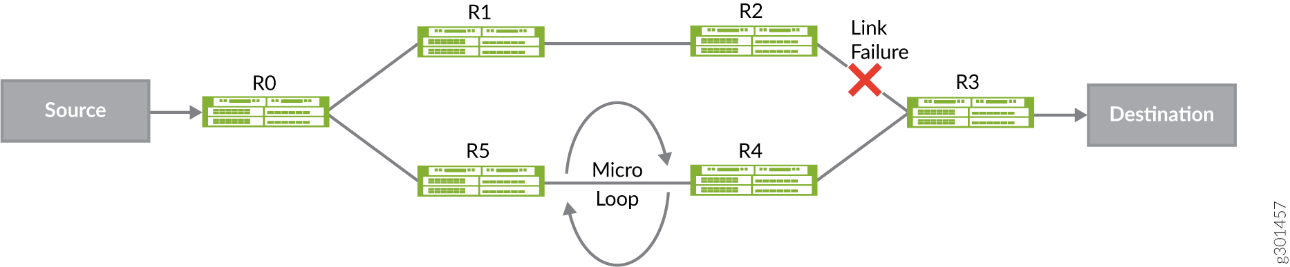
In the Figure 1, the primary path from Source to Destination is SR0R1R2R3D. When the link between R2 and R3 fails, traffic sent from S to D, is subject to transient forwarding loops while routers update their forwarding state for destination D.
• If R0 updates its forwarding state before R5, packets loop between R0 and R5
• If both R0 and R5, have updated their forwarding states, and R4 has not, packets loop between R4 and R5.
• R0 detects the link failure between R2 and R3, and temporarily steers traffic destined to Destination over SR path [NodeSID(R4), AdjSID(R4->R3), D].
• When the configured timeout elapses, R0 just uses the node-SID to D to reach the destination.
Microloop Avoidance in OSPFv2 Networks with Segment Routing
Enable
a post convergence path calculation on a device to avoid microloops if a link or metric
change occurs in an OSPFv2 segment routed network. To configure microloop avoidance in an
OSPFv2 segment routing network for both local and remote network events including link down,
link-up, and metric-change, include the maximum-labelsdelay
milliseconds statement at the [edit protocols ospf
spf-options microloop avoidance post-convergence-path] hierarchy level. For
effective microloop avoidance, configure this feature on all the nodes in the network.
Micro-loop avoidance is not a replacement for local repair mechanisms like TI-LFA which detects local failure very fast and activates a pre-computed loop-free-alternative path.
Routers that implement micro-loop avoidance compute the micro-loop avoiding path only after receiving the link state update for the event. So, micro-loop avoidance mechanism is not a replacement for local repair mechanisms like TI-LFA which detects local failure very fast and activates a pre-computed loop-free-alternative path at PFE level. In the above example, if local repair mechanism is not present for the R2R3 failure, there will be a lot of traffic loss before R0 can detect the failure (through global convergence) and program a micro-loop avoiding path. Micro-loop avoidance cannot avoid traffic loss due to delayed detection of the failure. Microloop avoidance avoids traffic loss due to micro-loops only. Both local-repair mechanisms like TI-LFA and micro-loop avoidance, have to be enabled on all the nodes in the network to ensure that traffic loss is in milli-seconds range.
To avoid micro-loops, the following process is used:
1. After computing the new path to D, for a predetermined time, R installs an entry for D that steers packets to D through a loop-free segment routed path. This time should be greater than worst case delay of any router in the network.
2. After the configured time delay, R installs the post-convergence route entry for D, which is without any SIDs.
Supported and Unsupported Features
Junos OS supports microloop avoidance in the following scenarios:
-
Microloop avoidance is supported on all the Junos OS platforms that support OSPF routing protocol.
-
Microloop avoidance is supported for IPv4 networks only.
-
Microloop avoidance is supported for flexible algorithm topologies.
Junos OS does not support the following features in conjunction with microloop avoidance:
- Microloop avoidance path that needs more than 8 labels is not supported. The maximum number of labels installed for microloop avoidance path is 8. For the microloop avoidance ECMP path to be usable, the number of labels must be less than or equal to maximum labels.
- Cannot prevent traffic loss because of slow control plane convergence.
- OSPFv2 multi-topology is not supported with microloop avoidance.
- Adjacency SIDs are not supported with microloop avoidance.
- If shortcuts are available OSPFv2 does not provide a microloop avoidance path.
Configuring Segment Routing Microloop Avoidance in OSPFv2 Networks
Overview
Microloops are packet forwarding loops that occur in the network following network change events such as link down, link up, or metric change. When a network change event occurs, different routers update their forwarding states at different times. This can lead to packets getting looped between upstream and downstream routers for a transient period, resulting in packet loss, jitter, and out-of-order packets. Microloops can consume the available bandwidth of the links, which impacts the efficient transmission of useful packets.
Microloop avoidance can prevent forwarding of looping packets. The segment routing microloop avoidance detects if microloops are possible following a topology change. When a network change event is detected, the routes are programmed to take the post-convergence path, that uses a combination of node and adjacency SIDs. This ensures the routers that might not yet have converged do not loop the packets causing microloops. This behavior lasts for a configurable delay. Once the delay timer expires, routes are programmed normally by using node-SID of the destinations.
Requirements
This example uses the following hardware and software components:
-
Eight MX Series routers.
-
Junos OS Release 22.1R1 or later.
Topology
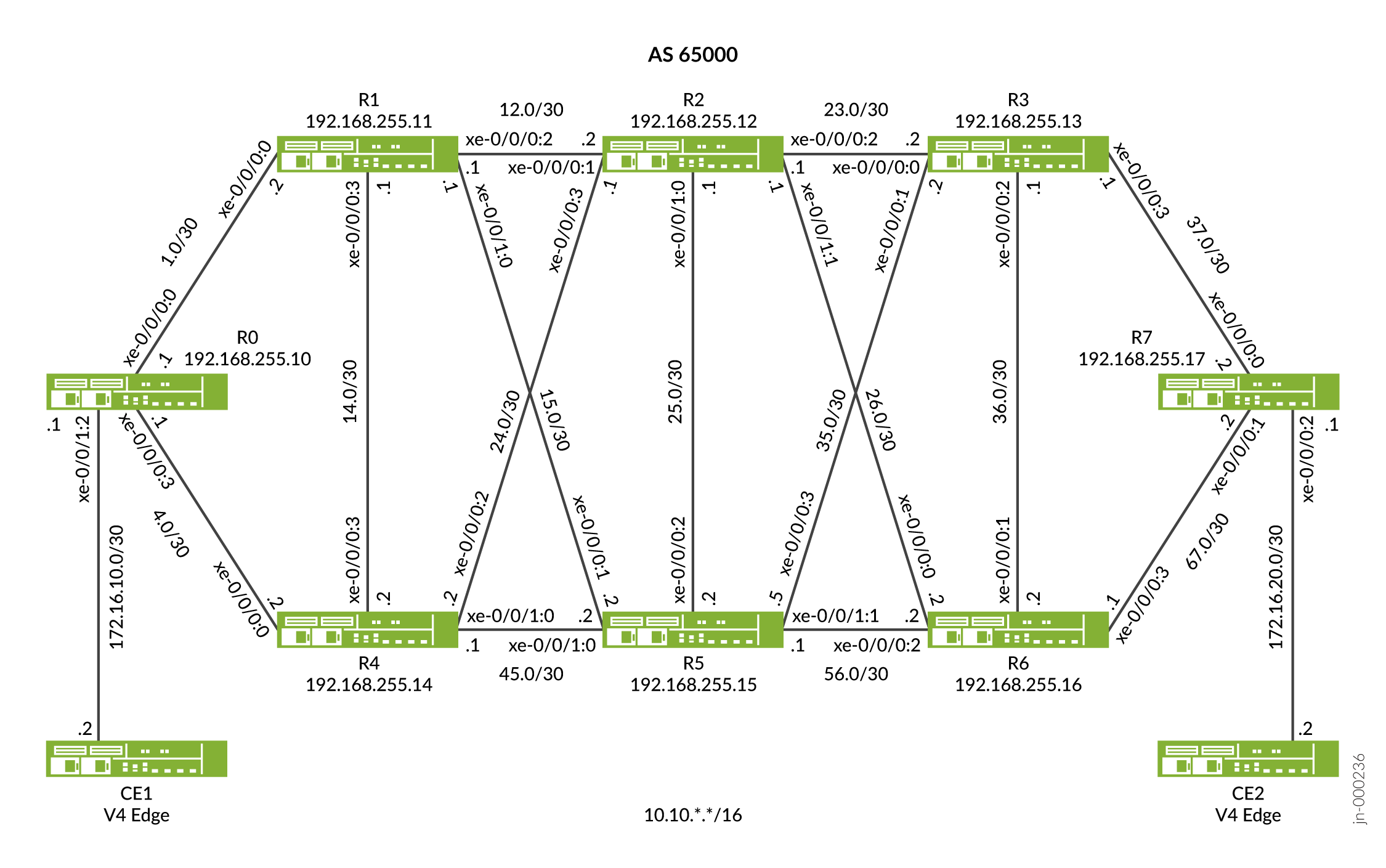
In Figure 2 device R0 and device R7 are the ingress and egress routers that support devices CE1 and CE2. The devices R1, R2, R3, R4, R5, and R6 comprise an IPv4 only provider core network. All the devices belong to the same autonomous system. OSPFv2 is the interior gateway protocol in the core configured to support microloop avoidance. In this example the device R2 is configured as an IPv4 route reflector with IBGP peering sessions to both R0 and R7. No other routers speak BGP in this example. The Device R6 has the firewall filter configured to detect packets with microloops if any following a link down event.
Configuration
CLI Quick Configuration
To quickly configure this example, copy the following commands, paste them into a text file, remove any line breaks, change any details necessary to match your network configuration, and then copy and paste the commands into the CLI at the [edit] hierarchy level.
Device R0
set interfaces xe-0/0/0:0 description To_R1
set interfaces xe-0/0/0:0 unit 0 family inet address 10.10.1.1/30
set interfaces xe-0/0/0:0 unit 0 family mpls
set interfaces xe-0/0/0:3 description To_R4
set interfaces xe-0/0/0:3 unit 0 family inet address 10.10.4.1/30
set interfaces xe-0/0/0:3 unit 0 family mpls
set interfaces xe-0/0/1:2 description to_CE1
set interfaces xe-0/0/1:2 unit 1 family inet address 172.16.10.2/30
set interfaces xe-0/0/1:2 unit 1 family mpls
set interfaces xe-0/0/1:2 unit 4 family inet address 172.16.11.2/30
set interfaces xe-0/0/1:2 unit 4 family mpls
set interfaces lo0 unit 0 family inet address 192.168.255.10/32
set interfaces lo0 unit 0 family mpls
set policy-options policy-statement pplb then load-balance per-packet
set policy-options policy-statement prefix-sid term 1 from route-filter 192.168.255.10/32 exact
set policy-options policy-statement prefix-sid term 1 then prefix-segment index 1000
set policy-options policy-statement prefix-sid term 1 then prefix-segment node-segment
set policy-options policy-statement prefix-sid term 1 then accept
set routing-options router-id 192.168.255.10
set routing-options autonomous-system 65000
set routing-options forwarding-table export pplb
set protocols bgp group to-RR type internal
set protocols bgp group to-RR local-address 192.168.255.10
set protocols bgp group to-RR neighbor 192.168.255.12 family inet unicast
set protocols bgp group to-RR neighbor 192.168.255.12 family inet-vpn unicast per-prefix-label
set protocols mpls traffic-engineering
set protocols mpls label-range static-label-range 60001 100000
set protocols mpls interface all
set protocols mpls interface fxp0.0 disable
set protocols ospf spf-options microloop-avoidance post-convergence-path delay 60000
set protocols ospf backup-spf-options use-post-convergence-lfa maximum-labels 5
set protocols ospf backup-spf-options use-post-convergence-lfa maximum-backup-paths 8
set protocols ospf backup-spf-options use-source-packet-routing
set protocols ospf source-packet-routing prefix-segment prefix-sid
set protocols ospf source-packet-routing node-segment ipv4-index 0
set protocols ospf source-packet-routing srgb start-label 800000
set protocols ospf source-packet-routing srgb index-range 80000
set protocols ospf area 0.0.0.0 interface lo0.0 passive
set protocols ospf area 0.0.0.0 interface xe-0/0/0:0.0 interface-type p2p
set protocols ospf area 0.0.0.0 interface xe-0/0/0:0.0 metric 10
set protocols ospf area 0.0.0.0 interface xe-0/0/0:0.0 post-convergence-lfa node-protection
set protocols ospf area 0.0.0.0 interface xe-0/0/0:3.0 interface-type p2p
set protocols ospf area 0.0.0.0 interface xe-0/0/0:3.0 metric 10
set protocols ospf area 0.0.0.0 interface xe-0/0/0:3.0 post-convergence-lfa node-protection
Device R1
set interfaces xe-0/0/0:0 description To_R0
set interfaces xe-0/0/0:0 unit 0 family inet address 10.10.1.2/30
set interfaces xe-0/0/0:0 unit 0 family mpls
set interfaces xe-0/0/0:2 description To_R2
set interfaces xe-0/0/0:2 unit 0 family inet address 10.10.12.1/30
set interfaces xe-0/0/0:2 unit 0 family mpls
set interfaces xe-0/0/0:2 unit 1 family inet address 10.11.12.1/30
set interfaces xe-0/0/0:2 unit 1 family mpls
set interfaces xe-0/0/0:3 description to_R4
set interfaces xe-0/0/0:3 unit 0 family inet address 10.10.14.1/30
set interfaces xe-0/0/0:3 unit 0 family mpls
set interfaces xe-0/0/1:0 description to_R5
set interfaces xe-0/0/1:0 unit 0 family inet address 10.10.15.1/30
set interfaces xe-0/0/1:0 unit 0 family mpls
set interfaces lo0 unit 0 family inet address 192.168.255.11/32
set interfaces lo0 unit 0 family mpls
set policy-options policy-statement pplb then load-balance per-packet
set policy-options policy-statement prefix-sid term 1 from route-filter 192.168.255.11/32 exact
set policy-options policy-statement prefix-sid term 1 then prefix-segment index 1001
set policy-options policy-statement prefix-sid term 1 then prefix-segment node-segment
set policy-options policy-statement prefix-sid term 1 then accept
set routing-options router-id 192.168.255.11
set routing-options autonomous-system 65000
set routing-options forwarding-table export pplb
set protocols mpls traffic-engineering
set protocols mpls label-range static-label-range 60001 100000
set protocols mpls interface all
set protocols mpls interface fxp0.0 disable
set protocols ospf spf-options microloop-avoidance post-convergence-path delay 60000
set protocols ospf backup-spf-options use-post-convergence-lfa maximum-labels 5
set protocols ospf backup-spf-options use-post-convergence-lfa maximum-backup-paths 8
set protocols ospf backup-spf-options use-source-packet-routing
set protocols ospf source-packet-routing prefix-segment prefix-sid
set protocols ospf source-packet-routing node-segment ipv4-index 2
set protocols ospf source-packet-routing srgb start-label 800000
set protocols ospf source-packet-routing srgb index-range 80000
set protocols ospf area 0.0.0.0 interface lo0.0 passive
set protocols ospf area 0.0.0.0 interface xe-0/0/0:3.0 interface-type p2p
set protocols ospf area 0.0.0.0 interface xe-0/0/0:3.0 metric 110
set protocols ospf area 0.0.0.0 interface xe-0/0/0:3.0 post-convergence-lfa
set protocols ospf area 0.0.0.0 interface xe-0/0/1:0.0 interface-type p2p
set protocols ospf area 0.0.0.0 interface xe-0/0/1:0.0 metric 110
set protocols ospf area 0.0.0.0 interface xe-0/0/1:0.0 post-convergence-lfa
set protocols ospf area 0.0.0.0 interface xe-0/0/0:0.0 interface-type p2p
set protocols ospf area 0.0.0.0 interface xe-0/0/0:0.0 metric 10
set protocols ospf area 0.0.0.0 interface xe-0/0/0:0.0 post-convergence-lfa
set protocols ospf area 0.0.0.0 interface xe-0/0/0:0.1 interface-type p2p
set protocols ospf area 0.0.0.0 interface xe-0/0/0:0.1 metric 10
set protocols ospf area 0.0.0.0 interface xe-0/0/0:2.0 interface-type p2p
set protocols ospf area 0.0.0.0 interface xe-0/0/0:2.0 metric 10
set protocols ospf area 0.0.0.0 interface xe-0/0/0:2.0 post-convergence-lfa
set protocols ospf area 0.0.0.0 interface xe-0/0/0:2.1 interface-type p2p
set protocols ospf area 0.0.0.0 interface xe-0/0/0:2.1 metric 10
Device R2
set interfaces xe-0/0/0:1 description To_R1
set interfaces xe-0/0/0:1 unit 0 family inet address 10.10.12.2/30
set interfaces xe-0/0/0:1 unit 0 family mpls
set interfaces xe-0/0/0:1 unit 1 family inet address 10.11.12.2/30
set interfaces xe-0/0/0:1 unit 1 family inet6
set interfaces xe-0/0/0:1 unit 1 family mpls
set interfaces xe-0/0/0:2 description To_R3
set interfaces xe-0/0/0:2 unit 0 family inet address 10.10.23.1/30
set interfaces xe-0/0/0:2 unit 0 family mpls
set interfaces xe-0/0/0:3 description To_R4
set interfaces xe-0/0/0:3 unit 0 family inet address 10.10.24.1/30
set interfaces xe-0/0/0:3 unit 0 family mpls
set interfaces xe-0/0/1:0 description To_R5
set interfaces xe-0/0/1:0 unit 0 family inet address 10.10.25.1/30
set interfaces xe-0/0/1:0 unit 0 family mpls
set interfaces xe-0/0/1:1 description To_R6
set interfaces xe-0/0/1:1 unit 0 family inet address 10.10.26.1/30
set interfaces xe-0/0/1:1 unit 0 family mpls
set interfaces lo0 unit 0 family inet address 192.168.255.12/32
set interfaces lo0 unit 0 family mpls
set policy-options policy-statement pplb then load-balance per-packet
set policy-options policy-statement prefix-sid term 1 from route-filter 192.168.255.12/32 exact
set policy-options policy-statement prefix-sid term 1 then prefix-segment index 1002
set policy-options policy-statement prefix-sid term 1 then prefix-segment node-segment
set policy-options policy-statement prefix-sid term 1 then accept
set routing-options router-id 192.168.255.12
set routing-options autonomous-system 65000
set routing-options forwarding-table export pplb
set protocols bgp group to-RR type internal
set protocols bgp group to-RR local-address 192.168.255.12
set protocols bgp group to-RR neighbor 192.168.255.17 family inet unicast
set protocols bgp cluster 192.168.255.12
set protocols mpls traffic-engineering
set protocols mpls label-range static-label-range 60001 100000
set protocols mpls interface all
set protocols mpls interface fxp0.0 disable
set protocols ospf spf-options microloop-avoidance post-convergence-path delay 60000
set protocols ospf backup-spf-options use-post-convergence-lfa maximum-labels 5
set protocols ospf backup-spf-options use-post-convergence-lfa maximum-backup-paths 8
set protocols ospf backup-spf-options use-source-packet-routing
set protocols ospf source-packet-routing prefix-segment prefix-sid
set protocols ospf source-packet-routing node-segment ipv4-index 4
set protocols ospf source-packet-routing srgb start-label 800000
set protocols ospf source-packet-routing srgb index-range 80000
set protocols ospf area 0.0.0.0 interface lo0.0 passive
set protocols ospf area 0.0.0.0 interface xe-0/0/0:3.0 interface-type p2p
set protocols ospf area 0.0.0.0 interface xe-0/0/0:3.0 metric 110
set protocols ospf area 0.0.0.0 interface xe-0/0/0:3.0 post-convergence-lfa node-protection
set protocols ospf area 0.0.0.0 interface xe-0/0/1:0.0 interface-type p2p
set protocols ospf area 0.0.0.0 interface xe-0/0/1:0.0 metric 110
set protocols ospf area 0.0.0.0 interface xe-0/0/1:0.0 post-convergence-lfa node-protection
set protocols ospf area 0.0.0.0 interface xe-0/0/1:1.0 interface-type p2p
set protocols ospf area 0.0.0.0 interface xe-0/0/1:1.0 metric 110
set protocols ospf area 0.0.0.0 interface xe-0/0/1:1.0 post-convergence-lfa node-protection
set protocols ospf area 0.0.0.0 interface xe-0/0/0:2.0 interface-type p2p
set protocols ospf area 0.0.0.0 interface xe-0/0/0:2.0 metric 10
set protocols ospf area 0.0.0.0 interface xe-0/0/0:2.0 post-convergence-lfa node-protection
set protocols ospf area 0.0.0.0 interface xe-0/0/0:1.0 interface-type p2p
set protocols ospf area 0.0.0.0 interface xe-0/0/0:1.0 metric 10
set protocols ospf area 0.0.0.0 interface xe-0/0/0:1.0 post-convergence-lfa node-protection
set protocols ospf area 0.0.0.0 interface xe-0/0/0:1.1 interface-type p2p
set protocols ospf area 0.0.0.0 interface xe-0/0/0:1.1 metric 10
set protocols ospf area 0.0.0.0 interface xe-0/0/0:1.2 interface-type p2p
set protocols ospf area 0.0.0.0 interface xe-0/0/0:1.2 metric 10
set protocols ospf area 0.0.0.0 interface xe-0/0/0:1.3 interface-type p2p
set protocols ospf area 0.0.0.0 interface xe-0/0/0:1.3 metric 10
set protocols ospf area 0.0.0.0 interface xe-0/0/0:1.4 interface-type p2p
set protocols ospf area 0.0.0.0 interface xe-0/0/0:1.4 metric 10
Device R3
set interfaces xe-0/0/0:0 description To_R2
set interfaces xe-0/0/0:0 unit 0 family inet address 10.10.23.2/30
set interfaces xe-0/0/0:0 unit 0 family mpls
set interfaces xe-0/0/0:1 description To_R5
set interfaces xe-0/0/0:1 unit 0 family inet address 10.10.35.2/30
set interfaces xe-0/0/0:1 unit 0 family mpls
set interfaces xe-0/0/0:2 description To_R6
set interfaces xe-0/0/0:2 unit 0 family inet address 10.10.36.1/30
set interfaces xe-0/0/0:2 unit 0 family mpls
set interfaces xe-0/0/0:3 description To_R7
set interfaces xe-0/0/0:3 unit 0 family inet address 10.10.37.1/30
set interfaces xe-0/0/0:3 unit 0 family mpls
set interfaces lo0 unit 0 family inet address 192.168.255.13/32
set interfaces lo0 unit 0 family mpls
set policy-options policy-statement pplb then load-balance per-packet
set policy-options policy-statement prefix-sid term 1 from route-filter 192.168.255.13/32 exact
set policy-options policy-statement prefix-sid term 1 then prefix-segment index 1003
set policy-options policy-statement prefix-sid term 1 then prefix-segment node-segment
set policy-options policy-statement prefix-sid term 1 then accept
set routing-options router-id 192.168.255.13
set routing-options autonomous-system 65000
set routing-options forwarding-table export pplb
set protocols mpls traffic-engineering
set protocols mpls label-range static-label-range 60001 100000
set protocols mpls interface all
set protocols mpls interface fxp0.0 disable
set protocols ospf spf-options microloop-avoidance post-convergence-path delay 60000
set protocols ospf backup-spf-options use-post-convergence-lfa maximum-labels 5
set protocols ospf backup-spf-options use-post-convergence-lfa maximum-backup-paths 8
set protocols ospf backup-spf-options use-source-packet-routing
set protocols ospf source-packet-routing prefix-segment prefix-sid
set protocols ospf source-packet-routing node-segment ipv4-index 6
set protocols ospf source-packet-routing srgb start-label 800000
set protocols ospf source-packet-routing srgb index-range 80000
set protocols ospf area 0.0.0.0 interface lo0.0 passive
set protocols ospf area 0.0.0.0 interface xe-0/0/0:0.0 interface-type p2p
set protocols ospf area 0.0.0.0 interface xe-0/0/0:0.0 metric 10
set protocols ospf area 0.0.0.0 interface xe-0/0/0:0.0 post-convergence-lfa node-protection
set protocols ospf area 0.0.0.0 interface xe-0/0/0:1.0 interface-type p2p
set protocols ospf area 0.0.0.0 interface xe-0/0/0:1.0 metric 110
set protocols ospf area 0.0.0.0 interface xe-0/0/0:1.0 post-convergence-lfa node-protection
set protocols ospf area 0.0.0.0 interface xe-0/0/0:2.0 interface-type p2p
set protocols ospf area 0.0.0.0 interface xe-0/0/0:2.0 metric 110
set protocols ospf area 0.0.0.0 interface xe-0/0/0:2.0 post-convergence-lfa node-protection
set protocols ospf area 0.0.0.0 interface xe-0/0/0:3.0 interface-type p2p
set protocols ospf area 0.0.0.0 interface xe-0/0/0:3.0 metric 10
set protocols ospf area 0.0.0.0 interface xe-0/0/0:3.0 post-convergence-lfa node-protection
Device R4
set interfaces xe-0/0/0:0 description To_R0
set interfaces xe-0/0/0:0 unit 0 family inet address 10.10.4.2/30
set interfaces xe-0/0/0:0 unit 0 family mpls
set interfaces xe-0/0/0:2 description To_R2
set interfaces xe-0/0/0:2 unit 0 family inet address 10.10.24.2/30
set interfaces xe-0/0/0:2 unit 0 family mpls
set interfaces xe-0/0/0:3 description To_R1
set interfaces xe-0/0/0:3 unit 0 family inet address 10.10.14.2/30
set interfaces xe-0/0/0:3 unit 0 family mpls
set interfaces xe-0/0/1:0 description To_R5
set interfaces xe-0/0/1:0 unit 0 family inet address 10.10.45.1/30
set interfaces xe-0/0/1:0 unit 0 family mpls
set interfaces lo0 unit 0 family inet address 192.168.255.14/32
set interfaces lo0 unit 0 family mpls
set policy-options policy-statement pplb then load-balance per-packet
set policy-options policy-statement prefix-sid term 1 from route-filter 192.168.255.14/32 exact
set policy-options policy-statement prefix-sid term 1 then prefix-segment index 1004
set policy-options policy-statement prefix-sid term 1 then prefix-segment node-segment
set policy-options policy-statement prefix-sid term 1 then accept
set routing-options router-id 192.168.255.14
set routing-options forwarding-table export pplb
set routing-options autonomous-system 65000
set protocols mpls traffic-engineering
set protocols mpls label-range static-label-range 60001 100000
set protocols mpls interface all
set protocols mpls interface fxp0.0 disable
set protocols ospf spf-options microloop-avoidance post-convergence-path delay 60000
set protocols ospf backup-spf-options use-post-convergence-lfa maximum-labels 5
set protocols ospf backup-spf-options use-post-convergence-lfa maximum-backup-paths 8
set protocols ospf backup-spf-options use-source-packet-routing
set protocols ospf source-packet-routing prefix-segment prefix-sid
set protocols ospf source-packet-routing node-segment ipv4-index 8
set protocols ospf source-packet-routing srgb start-label 800000
set protocols ospf source-packet-routing srgb index-range 80000
set protocols ospf area 0.0.0.0 interface lo0.0 passive
set protocols ospf area 0.0.0.0 interface xe-0/0/0:0.0 interface-type p2p
set protocols ospf area 0.0.0.0 interface xe-0/0/0:0.0 metric 10
set protocols ospf area 0.0.0.0 interface xe-0/0/0:0.0 post-convergence-lfa node-protection
set protocols ospf area 0.0.0.0 interface xe-0/0/1:0.0 interface-type p2p
set protocols ospf area 0.0.0.0 interface xe-0/0/1:0.0 metric 10
set protocols ospf area 0.0.0.0 interface xe-0/0/1:0.0 post-convergence-lfa node-protection
set protocols ospf area 0.0.0.0 interface xe-0/0/0:2.0 interface-type p2p
set protocols ospf area 0.0.0.0 interface xe-0/0/0:2.0 metric 110
set protocols ospf area 0.0.0.0 interface xe-0/0/0:2.0 post-convergence-lfa node-protection
set protocols ospf area 0.0.0.0 interface xe-0/0/0:3.0 interface-type p2p
set protocols ospf area 0.0.0.0 interface xe-0/0/0:3.0 metric 110
set protocols ospf area 0.0.0.0 interface xe-0/0/0:3.0 post-convergence-lfa node-protection
Device R5
set interfaces xe-0/0/0:1 description To_R1
set interfaces xe-0/0/0:1 unit 0 family inet address 10.10.15.2/30
set interfaces xe-0/0/0:1 unit 0 family mpls
set interfaces xe-0/0/0:2 description To_R2
set interfaces xe-0/0/0:2 unit 0 family inet address 10.10.25.2/30
set interfaces xe-0/0/0:2 unit 0 family mpls
set interfaces xe-0/0/0:3 description To_R3
set interfaces xe-0/0/0:3 unit 0 family inet address 10.10.35.2/30
set interfaces xe-0/0/0:3 unit 0 family mpls
set interfaces xe-0/0/1:0 description To_R4
set interfaces xe-0/0/1:0 unit 0 family inet address 10.10.45.2/30
set interfaces xe-0/0/1:0 unit 0 family mpls
set interfaces xe-0/0/1:1 description To_R6
set interfaces xe-0/0/1:1 unit 0 family inet address 10.10.56.1/30
set interfaces xe-0/0/1:1 unit 0 family mpls
set interfaces lo0 unit 0 family inet address 192.168.255.15/32
set interfaces lo0 unit 0 family mpls
set policy-options policy-statement pplb then load-balance per-packet
set policy-options policy-statement prefix-sid term 1 from route-filter 192.168.255.15/32 exact
set policy-options policy-statement prefix-sid term 1 then prefix-segment index 1005
set policy-options policy-statement prefix-sid term 1 then prefix-segment node-segment
set policy-options policy-statement prefix-sid term 1 then accept
set routing-options router-id 192.168.255.15
set routing-options autonomous-system 65000
set routing-options forwarding-table export pplb
set protocols mpls traffic-engineering
set protocols mpls label-range static-label-range 60001 100000
set protocols mpls interface all
set protocols mpls interface fxp0.0 disable
set protocols ospf spf-options microloop-avoidance post-convergence-path delay 60000
set protocols ospf backup-spf-options use-post-convergence-lfa maximum-labels 5
set protocols ospf backup-spf-options use-post-convergence-lfa maximum-backup-paths 8
set protocols ospf backup-spf-options use-source-packet-routing
set protocols ospf source-packet-routing node-segment ipv4-index 10
set protocols ospf source-packet-routing srgb start-label 800000
set protocols ospf source-packet-routing srgb index-range 80000
set protocols ospf area 0.0.0.0 interface lo0.0 passive
set protocols ospf area 0.0.0.0 interface xe-0/0/1:0.0 interface-type p2p
set protocols ospf area 0.0.0.0 interface xe-0/0/1:0.0 metric 10
set protocols ospf area 0.0.0.0 interface xe-0/0/1:0.0 post-convergence-lfa node-protection
set protocols ospf area 0.0.0.0 interface xe-0/0/0:1.0 interface-type p2p
set protocols ospf area 0.0.0.0 interface xe-0/0/0:1.0 metric 110
set protocols ospf area 0.0.0.0 interface xe-0/0/0:1.0 post-convergence-lfa node-protection
set protocols ospf area 0.0.0.0 interface xe-0/0/0:2.0 interface-type p2p
set protocols ospf area 0.0.0.0 interface xe-0/0/0:2.0 metric 110
set protocols ospf area 0.0.0.0 interface xe-0/0/0:2.0 post-convergence-lfa node-protection
set protocols ospf area 0.0.0.0 interface xe-0/0/0:3.0 interface-type p2p
set protocols ospf area 0.0.0.0 interface xe-0/0/0:3.0 metric 110
set protocols ospf area 0.0.0.0 interface xe-0/0/0:3.0 post-convergence-lfa node-protection
set protocols ospf area 0.0.0.0 interface xe-0/0/1:1.0 interface-type p2p
set protocols ospf area 0.0.0.0 interface xe-0/0/1:1.0 metric 10
set protocols ospf area 0.0.0.0 interface xe-0/0/1:1.0 post-convergence-lfa node-protection
Device R6
set interfaces xe-0/0/0:0 description To_R2
set interfaces xe-0/0/0:0 unit 0 family inet address 10.10.26.2/30
set interfaces xe-0/0/0:0 unit 0 family mpls
set interfaces xe-0/0/0:1 description To_R3
set interfaces xe-0/0/0:1 unit 0 family inet address 10.10.36.2/30
set interfaces xe-0/0/0:1 unit 0 family mpls
set interfaces xe-0/0/0:2 description To_R5
set interfaces xe-0/0/0:2 unit 0 family inet filter output v4filter
set interfaces xe-0/0/0:2 unit 0 family inet address 10.10.56.2/30
set interfaces xe-0/0/0:2 unit 0 family mpls filter output mplsfilter
set interfaces xe-0/0/0:3 description To_R7
set interfaces xe-0/0/0:3 unit 0 family inet address 10.10.67.1/30
set interfaces xe-0/0/0:3 unit 0 family mpls
set interfaces lo0 unit 0 family inet address 192.168.255.16/32
set interfaces lo0 unit 0 family inet address 192.168.255.61/32
set interfaces lo0 unit 0 family mpls
set policy-options policy-statement pplb then load-balance per-packet
set policy-options policy-statement prefix-sid term 1 from route-filter 192.168.255.16/32 exact
set policy-options policy-statement prefix-sid term 1 then prefix-segment index 1006
set policy-options policy-statement prefix-sid term 1 then prefix-segment node-segment
set policy-options policy-statement prefix-sid term 1 then accept
set policy-options policy-statement prefix-sid term 2 from route-filter 192.168.255.61/32 exact
set policy-options policy-statement prefix-sid term 2 then prefix-segment index 1106
set policy-options policy-statement prefix-sid term 2 then accept
set firewall family inet filter v4filter term t1 from destination-address 8.3.0.0/16
set firewall family inet filter v4filter term t1 then accept
set firewall family inet filter v4filter term t6 then accept
set firewall family mpls filter mplsfilter term t1 from ip-version ipv4 destination-address 10.8.0.1/16
set firewall family mpls filter mplsfilter term t1 then count v4sr-nsid-cnt
set firewall family mpls filter mplsfilter term t1 then accept
set firewall family mpls filter mplsfilter term t2 from ip-version ipv4 destination-address 10.9.0.1/16
set firewall family mpls filter mplsfilter term t2 then count v4sr-psid-cnt
set firewall family mpls filter mplsfilter term t2 then accept
set firewall family mpls filter mplsfilter term t3 then accept
set firewall family mpls filter mplsfilter term t4 then accept
set firewall family mpls filter mplsfilter term t6 then accept
set routing-options router-id 192.168.255.16
set routing-options autonomous-system 65000
set routing-options forwarding-table export pplb
set protocols mpls traffic-engineering
set protocols mpls label-range static-label-range 60001 100000
set protocols mpls interface all
set protocols mpls interface fxp0.0 disable
set protocols ospf spf-options microloop-avoidance post-convergence-path delay 60000
set protocols ospf backup-spf-options use-post-convergence-lfa maximum-labels 5
set protocols ospf backup-spf-options use-post-convergence-lfa maximum-backup-paths 8
set protocols ospf backup-spf-options use-source-packet-routing
set protocols ospf source-packet-routing prefix-segment prefix-sid
set protocols ospf source-packet-routing node-segment ipv4-index 12
set protocols ospf source-packet-routing srgb start-label 800000
set protocols ospf source-packet-routing srgb index-range 80000
set protocols ospf area 0.0.0.0 interface lo0.0 passive
set protocols ospf area 0.0.0.0 interface xe-0/0/0:2.0 interface-type p2p
set protocols ospf area 0.0.0.0 interface xe-0/0/0:2.0 metric 10
set protocols ospf area 0.0.0.0 interface xe-0/0/0:2.0 post-convergence-lfa node-protection
set protocols ospf area 0.0.0.0 interface xe-0/0/0:0.0 interface-type p2p
set protocols ospf area 0.0.0.0 interface xe-0/0/0:0.0 metric 110
set protocols ospf area 0.0.0.0 interface xe-0/0/0:0.0 post-convergence-lfa node-protection
set protocols ospf area 0.0.0.0 interface xe-0/0/0:1.0 interface-type p2p
set protocols ospf area 0.0.0.0 interface xe-0/0/0:1.0 metric 110
set protocols ospf area 0.0.0.0 interface xe-0/0/0:1.0 post-convergence-lfa node-protection
set protocols ospf area 0.0.0.0 interface xe-0/0/0:3.0 interface-type p2p
set protocols ospf area 0.0.0.0 interface xe-0/0/0:3.0 metric 100
set protocols ospf area 0.0.0.0 interface xe-0/0/0:3.0 post-convergence-lfa node-protection
Device R7
set interfaces xe-0/0/0:0 description To_R3
set interfaces xe-0/0/0:0 unit 0 family inet address 10.10.37.2/24
set interfaces xe-0/0/0:0 unit 0 family mpls
set interfaces xe-0/0/0:1 description To_R6
set interfaces xe-0/0/0:1 unit 0 family inet address 10.10.67.2/30
set interfaces xe-0/0/0:1 unit 0 family mpls
set interfaces xe-0/0/0:2 description to_CE2
set interfaces xe-0/0/0:2 unit 4 family inet address 172.16.20.1/30
set interfaces xe-0/0/0:2 unit 4 family mpls
set interfaces lo0 unit 0 family inet address 192.168.255.17/32
set interfaces lo0 unit 0 family inet address 192.168.255.71/32
set interfaces lo0 unit 0 family mpls
set policy-options policy-statement payload_9 term 1 from route-filter 10.7.0.1/16 orlonger
set policy-options policy-statement payload_9 term 1 then next-hop 192.168.255.17
set policy-options policy-statement payload_9 term 1 then accept
set policy-options policy-statement payload_9 term 2 from route-filter 10.8.0.1/16 orlonger
set policy-options policy-statement payload_9 term 2 then next-hop 192.168.255.17
set policy-options policy-statement payload_9 term 2 then accept
set policy-options policy-statement payload_9 term 3 from route-filter 8.2.0.0/16 orlonger
set policy-options policy-statement payload_9 term 3 then next-hop 192.168.255.71
set policy-options policy-statement payload_9 term 4 then reject
set policy-options policy-statement pplb then load-balance per-packet
set policy-options policy-statement prefix-sid term 1 from route-filter 192.168.255.17/32 exact
set policy-options policy-statement prefix-sid term 1 then prefix-segment index 1007
set policy-options policy-statement prefix-sid term 1 then prefix-segment node-segment
set policy-options policy-statement prefix-sid term 1 then accept
set policy-options policy-statement prefix-sid term 2 from route-filter 192.168.255.71/32 exact
set policy-options policy-statement prefix-sid term 2 then prefix-segment index 1107
set policy-options policy-statement prefix-sid term 2 then accept
set policy-options policy-statement v4stat term 1 from protocol static
set policy-options policy-statement v4stat term 1 from route-filter 100.100.100.1/32 orlonger
set policy-options policy-statement v4stat term 1 then accept
set policy-options policy-statement v4_prefixes term 1 from route-filter 8.3.0.0/16 orlonger
set policy-options policy-statement v4_prefixes term 1 then accept
set policy-options policy-statement v4_prefixes term 3 then reject
set routing-options rib inet.0 static route 100.100.100.1/32 receive
set routing-options router-id 192.168.255.17
set routing-options autonomous-system 65000
set routing-options forwarding-table export pplb
set protocols bgp group to-RR type internal
set protocols bgp group to-RR local-address 192.168.255.17
set protocols bgp group to-RR neighbor 192.168.255.12 family inet unicast
set protocols bgp group to-RR neighbor 192.168.255.12 export payload_9
set protocols bgp group to-CE1 type external
set protocols bgp group to-CE1 local-address 172.16.20.1
set protocols bgp group to-CE1 neighbor 172.16.20.2 family inet unicast
set protocols bgp group to-CE1 neighbor 172.16.20.2 peer-as 700
set protocols bgp group to-CE1 neighbor 172.16.20.2 local-as 100
set protocols mpls traffic-engineering
set protocols mpls label-range static-label-range 60001 100000
set protocols mpls interface all
set protocols mpls interface fxp0.0 disable
set protocols ospf backup-spf-options use-post-convergence-lfa maximum-labels 5
set protocols ospf backup-spf-options use-post-convergence-lfa maximum-backup-paths 8
set protocols ospf backup-spf-options use-source-packet-routing
set protocols ospf source-packet-routing prefix-segment prefix-sid
set protocols ospf source-packet-routing node-segment ipv4-index 14
set protocols ospf source-packet-routing srgb start-label 800000
set protocols ospf source-packet-routing srgb index-range 80000
set protocols ospf area 0.0.0.0 interface lo0.0 passive
set protocols ospf area 0.0.0.0 interface xe-0/0/0:0.0 interface-type p2p
set protocols ospf area 0.0.0.0 interface xe-0/0/0:0.0 metric 10
set protocols ospf area 0.0.0.0 interface xe-0/0/0:0.0 post-convergence-lfa node-protection
set protocols ospf area 0.0.0.0 interface xe-0/0/0:1.0 interface-type p2p
set protocols ospf area 0.0.0.0 interface xe-0/0/0:1.0 metric 10
set protocols ospf area 0.0.0.0 interface xe-0/0/0:1.0 post-convergence-lfa node-protection
Configuring Device R0
Step-by-Step Procedure
To configure segment routing microloop avoidance path in an OSPFv2 network, perform the following steps on the R0 device:
-
Configure the device interfaces to enable IP and MPLS transport.
[edit]
user@R0#set interfaces xe-0/0/0:0 description To_R1
user@R0#set interfaces xe-0/0/0:0 unit 0 family inet address 10.10.1.1/30
uesr@R0#set interfaces xe-0/0/0:0 unit 0 family mpls
user@R0#set interfaces xe-0/0/0:3 description To_R4
user@R0#set interfaces xe-0/0/0:3 unit 0 family inet address 10.10.4.1/30
uesr@R0#set interfaces xe-0/0/0:3 unit 0 family mpls
user@R0#set interfaces xe-0/0/1:2 description to_CE1
user@R0#set interfaces xe-0/0/1:2 unit 1 family inet address 172.16.10.2/30
user@R0#set interfaces xe-0/0/1:2 unit 1 family mpls
-
Configure the loopback interface (lo0) addresses that is used as router ID for OSPF sessions.
[edit]
user@R0#set interfaces lo0 unit 0 family inet address 192.168.255.10/32
user@R0#set interfaces lo0 unit 0 family inet address 192.168.255.18/32
-
Configure the router ID and autonomous system (AS) number to propagate routing information within a set of routing devices that belong to the same AS.
[edit]
user@R0#set routing-options router-id 192.168.255.10
user@R0#set routing-options autonomous-system 65000
-
Define a policy to load balance packets and apply the per-packet policy to enable load balancing of traffic.
[edit]
user@R0#set policy-options policy-statement pplb then load-balance per-packet
user@R0#set routing-options forwarding-table export pplb
-
Configure R0 to advertise the loopback address. The
prefix-segment indexoption sets the base label for each router's loopback. In this example the base index is set to reflect| the router number. As a result, R0 uses 1000.[edit] user@R0#set policy-options policy-statement prefix-sid term 1 from route-filter 192.168.255.10/32 exact user@R0#set policy-options policy-statement prefix-sid term 1 then prefix-segment index 1000 user@R0#set policy-options policy-statement prefix-sid term 1 then prefix-segment node-segment user@R0#set policy-options policy-statement prefix-sid term 1 then accept
-
Configure MPLS on all interfaces excluding the management interface. Also enable traffic engineering.
[edit]
user@R0#set protocols mpls interface all
user@R0#set protocols mpls interface fxp0.0 disable
user@R0#set protocols mpls traffic-engineering
-
Configure the MPLS label range to assign static labels for the links.
[edit]
user@R0#set protocols mpls label-range static-label-range 60001 100000
-
Configure BGP peering between R0 and the route reflector R2. Configure the unicast network layer reachability information (NRLI) to allocate a unique label for each prefix on the devices.
[edit]
user@R0#set protocols bgp group to-RR type internal
user@R0#set protocols bgp group to-RR local-address 192.168.255.10
user@R0#set protocols bgp group to-RR neighbor 192.168.255.12 family inet unicast
user@R0#set protocols bgp group to-RR neighbor 192.168.255.12 family inet-vpn unicast per-prefix-label
-
Configure TI-LFA to enable protection against link and node failures. SR using TI-LFA provides faster restoration of network connectivity by routing the traffic instantly to a backup or an alternate path if the primary path fails or becomes unavailable.
[edit]
user@host#set protocols ospf backup-spf-options use-source-packet-routing
-
Configure backup shortest path first (SPF) attributes such as maximum equal-cost multipath (ECMP) as 8 and maximum number of labels as 5 for TI-LFA for the OSPFv2 protocol.
[edit]
user@host#set protocols ospf backup-spf-options use-post-convergence-lfa maximum-labels 5
user@host#set protocols ospf backup-spf-options use-post-convergence-lfa maximum-backup-paths 8
-
Configure prefix segment attributes, the start label and the index range for segment routing global blocks (SRGBs) in SPRING for the OSPFv2 protocol.
[edit]
user@host#set protocols ospf source-packet-routing prefix-segment prefix-sid
user@host#set protocols ospf source-packet-routing node-segment ipv4-index 0
user@host#set protocols ospf source-packet-routing srgb start-label 800000
user@host#set protocols ospf source-packet-routing srgb index-range 80000
-
Configure the loopback interface as passive to ensure the protocols do not run over the loopback interface and that the loopback interface is advertised correctly throughout the network.
[edit]
user@host#set protocols ospf area 0.0.0.0 interface lo0.0 passive
-
Configure OSPF area 0 on the point-to-point interface of the device R0.
[edit]
user@host#set protocols ospf area 0.0.0.0 interface xe-0/0/0:0.0 interface-type p2p
user@host#set protocols ospf area 0.0.0.0 interface xe-0/0/0:0.0 metric 10
user@host#set protocols ospf area 0.0.0.0 interface xe-0/0/0:3.0 interface-type p2p
user@host#set protocols ospf area 0.0.0.0 interface xe-0/0/0:3.0 metric 10
-
Configure the computation and installation of a backup path that follows the post-convergence path on the given area and interface for the OSPFv2 protocol. Also enable node-link protection on the these interfaces that follow post-convergence path.
[edit]
user@host#set protocols ospf area 0.0.0.0 interface xe-0/0/0:0.0 post-convergence-lfa node-protection
user@host#set protocols ospf area 0.0.0.0 interface xe-0/0/0:3.0 post-convergence-lfa node-protection
-
Configure microloop avoidance that temporarily installs a post-convergence path for routes potentially affected by microloops and specify a delay time period of 60000 milliseconds for the OSPFv2 protocol. The temporary path reverts to the node SIDs of the destination after the delay timer expires.
[edit]
user@host#set protocols ospf spf-options microloop-avoidance post-convergence-path delay 60000
Results
Check the results of the configuration:
interfaces {
    xe-0/0/0:0 {
        description To_R1;
        unit 0 {
            family inet {
                address 10.10.1.1/30;
            }
            family mpls;
        }
    }
    xe-0/0/0:3 {
        description To_R4;
        unit 0 {
            family inet {
                address 10.10.4.1/30;
            }
            family mpls;
        }
    }
    xe-0/0/1:2 {
        description to_CE1;
        unit 1 {
            family inet {
                address 172.16.10.2/30;
            }
            family mpls;
            }
        }
  }
    lo0 {
        unit 0 {
            family inet {
                address 192.168.255.10/32;
                address 192.168.255.18/32;
            }
            family mpls;
        }
    }
}
policy-options {
    policy-statement pplb {
        then {
            load-balance per-packet;
        }
    }
    policy-statement prefix-sid {
        term 1 {
            from {
                route-filter 192.168.255.10/32 exact;
            }
            then {
                prefix-segment {
                    index 1000;
                    node-segment;
                }
                accept;
            }
        }
        term 2 {
            from {
                route-filter 192.168.255.18/32 exact;
            }
            then {
                prefix-segment {
                    index 1100;
                }
                accept;
            }
        }
    }
}
routing-options {
    router-id 192.168.255.10;
    autonomous-system 100;
    forwarding-table {
        export pplb;
    }
}
protocols {
    bgp {
        group to-RR {
            type internal;
            local-address 192.168.255.10;
            neighbor 192.168.255.12 {
                family inet {
                    unicast;
                }
                family inet-vpn {
                    unicast {
                        per-prefix-label;
                    }
                }
            }
        }
    }
    mpls {
        traffic-engineering;
        label-range {
            static-label-range 60001 100000;
        }
        interface all;
        interface fxp0.0 {
            disable;
        }
    }
    ospf {
        spf-options {
            microloop-avoidance {
                post-convergence-path {
                    delay 60000;
                }
            }
        }
        backup-spf-options {
            use-post-convergence-lfa {
                maximum-labels 5;
                maximum-backup-paths 8;
            }
            use-source-packet-routing;
        }
        source-packet-routing {
            prefix-segment prefix-sid;
            node-segment ipv4-index 0;
            srgb start-label 800000 index-range 80000;
        }
        area 0.0.0.0 {
            interface lo0.0 {
                passive;
            }
            interface xe-0/0/0:0.0 {
                interface-type p2p;
                metric 10;
                post-convergence-lfa;
            }
            interface xe-0/0/0:3.0 {
                interface-type p2p;
                metric 10;
                post-convergence-lfa;
            }
        }
    }
}
Verification
Confirm that the configuration is working properly.
The following section explains microloop avoidance for a link down event.
- Verify Connectivity Between R0 and R7 Before the Link is Disabled Between R0 and R1
- Verify Disabling the Link Between R0 and R1
- Verify Microloop-avoidance Path Installed for the Destination After the Link is Disabled
- Verify Packets With Microloops
- Verify Microloop-avoidance Path Changes to Post-convergence- path After the Delay Timer Expires
- Verify Connectivity Between R0 and R7
- Verify the Path Changes to Microloop-avoidance Path After the Link is Enabled
Verify Connectivity Between R0 and R7 Before the Link is Disabled Between R0 and R1
Purpose
Verify that the Device R0 can reach the destinations on Device R7.
Action
From operational mode, run the ping command on the device R0.
user@R0>ping 192.168.255.17
PING 192.168.255.17 (192.168.255.17): 56 data bytes
64 bytes from 192.168.255.17: icmp_seq=0 ttl=61 time=41.493 ms
64 bytes from 192.168.255.17: icmp_seq=1 ttl=61 time=57.242 ms
64 bytes from 192.168.255.17: icmp_seq=2 ttl=61 time=44.977 ms
64 bytes from 192.168.255.17: icmp_seq=3 ttl=61 time=202.092 ms
64 bytes from 192.168.255.17: icmp_seq=4 ttl=61 time=60.495 ms
64 bytes from 192.168.255.17: icmp_seq=5 ttl=61 time=39.396 ms
64 bytes from 192.168.255.17: icmp_seq=6 ttl=61 time=79.993 ms
64 bytes from 192.168.255.17: icmp_seq=7 ttl=61 time=78.741 ms
8 packets transmitted, 8 received, 0% packet loss, time 7007ms
rtt min/avg/max/mdev = 38.194/47.998/60.879/8.727 ms
Meaning
These results confirm that the device R0 can reach device R7 in the OSPFv2 network.
Verify Disabling the Link Between R0 and R1
Purpose
To verify disabling the link between R0 and R1 on the device R0
Action
From configuration mode, run the disable interface command on the device R0
user@R0#disble interface xe-0/0/0:0
To verify the link is disabled, from operational mode, run the show interfaces command on the device R0
user@R0>show interfaces xe-0/0/0:0
Physical interface: xe-0/0/0:0, Administratively down, Physical link is Down
  Interface index: 149, SNMP ifIndex: 527
  Description: To_R1_1
  Link-level type: Ethernet, MTU: 1518, MRU: 1526, LAN-PHY mode, Speed: 10Gbps, BPDU Error: None, Loop Detect PDU Error: None, MAC-REWRITE Error: None, Loopback: None, Source filtering: Disabled, Flow control: Enabled, Speed Configuration: Auto
  Pad to minimum frame size: Disabled
  Device flags   : Present Running Down
  Interface flags: Hardware-Down Down SNMP-Traps Internal: 0x4000
  CoS queues     : 8 supported, 8 maximum usable queues
  Schedulers     : 0
  Current address: 2c:6b:f5:42:fe:00, Hardware address: 2c:6b:f5:42:fe:00
  Last flapped   : 2022-02-15 09:53:51 PST (00:00:10 ago)
  Input rate     : 0 bps (0 pps)
  Output rate    : 0 bps (0 pps)
  Active alarms  : None
  Active defects : None
  PCS statistics                      Seconds
    Bit errors                             0
    Errored blocks                         0
  Link Degrade :
    Link Monitoring                   :  Disable
  Interface transmit statistics: Disabled
Meaning
The output indicates the physical link between R0 and R1 is disabled and is administratively down.
Verify Microloop-avoidance Path Installed for the Destination After the Link is Disabled
Purpose
Verify microloop-avoidance path installed for the destination routes R7 from R0 when the link is disabled between R0 and R1 by verifying routes in the inet.3 table and route label details in the mpls.0 table.
Action
From operational mode, run the show route table inet.3 command on the device R0.
user@R0>show route table inet.3 192.168.255.17/32
inet.3: 25 destinations, 26 routes (25 active, 0 holddown, 0 hidden)
+ = Active Route, - = Last Active, * = Both

192.168.255.17/32         *[L-OSPF/10/5] 00:00:31, metric 130
                    >  to 192.168.255.14 via xe-0/0/0:3, Push 16, Push 801006(top)
From operational mode, run the show route label label value protocol ospf extensive command on the device R0.
user@R0>show route label 801007 protocol ospf extensive
mpls.0: 23 destinations, 23 routes (23 active, 0 holddown, 0 hidden)
801007 (1 entry, 1 announced)
TSI:
KRT in-kernel 801007 /52 -> {Swap 16, Push 801006 (top)}
        *L-OSPF Preference: 10/5
                Next hop type: Router, Next hop index: 649
                Address: 0x7a1ed58
                Next-hop reference count: 4, key opaque handle: 0x0
                Next hop: 10.10.4.2 via xe-0/0/0:3.0 weight 0x1, selected
                Label operation: Swap 16, Push 801006(top)
                Load balance label: Label 16: None; Label 801006: None
                Label element ptr: 0x8fd6ed0
                Label parent element ptr: 0x0
                Label element references: 1
                Label element child references: 0
                Label element lsp id: 0
                Session Id: 321
                State: <Active Int>
                Local AS:   100
                Age: 2:55:13    Metric: 130
                Validation State: unverified
                Area: 0.0.0.0
                Task: OSPF
                Announcement bits (1): 1-KRT
                AS path: I
                Thread: junos-main
Meaning
The output indicates that when the link between R0 and R1 goes down, the microloop-avoidance path is installed for R7 from R0 through R4 until the delay timer expires.
Verify Packets With Microloops
Purpose
Verify packets with microloops by using firewall counter information
Action
From operational mode, run the show firewall command on the device R6.
user@R6>show firewall
Filter: mplsfilter
Counters:
Name                                                Bytes              Packets
v4sr-nsid-cnt                                           0                    0
v4sr-psid-cnt                                           0                    0
Meaning
The output displays the mplsfilter configured on the device R6 to display microloops if there are any. The value 0 indicates there are no packets with microloops.
Verify Microloop-avoidance Path Changes to Post-convergence- path After the Delay Timer Expires
Purpose
Verify microloop-avoidance path installed for the destination routes R7 from R0 changes to post-convergence-path after the delay timer 60000 ms expires.
Action
From operational mode, run the show route table inet.3 command on the device R0.
user@R0>show route table inet.3 192.168.255.17/32
inet.3: 25 destinations, 26 routes (25 active, 0 holddown, 0 hidden)
+ = Active Route, - = Last Active, * = Both

192.168.255.17/32         *[L-OSPF/10/5] 00:00:31, metric 130
                    >  to 192.168.255.14 via xe-0/0/0:3, Push 801007
From operational mode, run the show route label label value protocol ospf extensive command on the device R0.
user@R0>show route label 801007 protocol ospf extensive
mpls.0: 23 destinations, 23 routes (23 active, 0 holddown, 0 hidden)
801007 (1 entry, 1 announced)
TSI:
KRT in-kernel 801007 /52 -> {Swap 801007}
        *L-OSPF Preference: 10/5
                Next hop type: Router, Next hop index: 615
                Address: 0x7a1c400
                Next-hop reference count: 4, key opaque handle: 0x0
                Next hop: 10.10.4.2 via xe-0/0/0:3.0 weight 0x1, selected
                Label operation: Swap 801007
                Load balance label: Label 801007: None;
                Label element ptr: 0x8fd6458
                Label parent element ptr: 0x0
                Label element references: 1
                Label element child references: 0
                Label element lsp id: 0
                Session Id: 321
                State: <Active Int>
                Local AS:   100
                Age: 2:55:13    Metric: 130
                Validation State: unverified
                Area: 0.0.0.0
                Task: OSPF
                Announcement bits (1): 1-KRT
                AS path: I
                Thread: junos-main
Meaning
The output indicates that the microloop-avoidance path is changed to post-convergence-path after the delay timer expires.
Verify Connectivity Between R0 and R7
Purpose
Verify that the Device R0 can reach the destinations on Device R7.
Action
From operational mode, run the ping command on the device R0.
user@R0>ping 192.168.255.17
PING 192.168.255.17 (192.168.255.17): 56 data bytes
64 bytes from 192.168.255.17: icmp_seq=0 ttl=61 time=41.493 ms
64 bytes from 192.168.255.17: icmp_seq=1 ttl=61 time=57.242 ms
64 bytes from 192.168.255.17: icmp_seq=2 ttl=61 time=44.977 ms
64 bytes from 192.168.255.17: icmp_seq=3 ttl=61 time=202.092 ms
64 bytes from 192.168.255.17: icmp_seq=4 ttl=61 time=60.495 ms
64 bytes from 192.168.255.17: icmp_seq=5 ttl=61 time=39.396 ms
64 bytes from 192.168.255.17: icmp_seq=6 ttl=61 time=79.993 ms
64 bytes from 192.168.255.17: icmp_seq=7 ttl=61 time=78.741 ms
8 packets transmitted, 8 received, 0% packet loss, time 7007ms
rtt min/avg/max/mdev = 38.194/47.998/60.879/8.727 ms
Meaning
These results confirm that the device R0 can reach device R7 in the OSPFv2 network and that the traffic flows with 0% packet loss in case of link down because of the microloop-avoidance path configured.
Verify the Path Changes to Microloop-avoidance Path After the Link is Enabled
Purpose
Verify the path changes to microloop-avoidance path for the destination when the link is enabled between R0 and R1.
Action
From operational mode, run the show route table inet.3 command on the device R0.
user@R0>show route table inet.3 192.168.255.17/32
inet.3: 26 destinations, 27 routes (26 active, 0 holddown, 0 hidden)
+ = Active Route, - = Last Active, * = Both

192.168.255.17/32         *[L-OSPF/10/5] 00:02:05, metric 40
                    >  to 192.168.255.11 via xe-0/0/0:0, Push 801007
                       to 192.168.255.14 via xe-0/0/0:3, Push 16, Push 801006(top)
From operational mode, run the show route label label value protocol ospf extensive command on the device R0.
user@R0>show route label 801007 protocol ospf extensive
mpls.0: 23 destinations, 23 routes (23 active, 0 holddown, 0 hidden)
801007 (1 entry, 1 announced)
TSI:
KRT in-kernel 801007 /52 -> {list:Swap 801007, Swap 16, Push 801006(top)}
        *L-OSPF Preference: 10/5
                Next hop type: Router, Next hop index: 615
                Address: 0x79329ac
                Next-hop reference count: 3, key opaque handle: 0x0
                Next hop: 10.10.4.2 via xe-0/0/0:3.0 weight 0x1, selected
                Label operation: Push 801007
                Load balance label: Label 801007: None;
                Label element ptr: 0x8fd6458
                Label parent element ptr: 0x0
                Label element references: 1
                Label element child references: 0
                Label element lsp id: 0
                Session Id: 0
                Next hop: 10.10.1.2 via xe-0/0/0:0.0 weight 0xf000, selected
                Label operation: Swap 16, Push 801006(top)
                Load balance label: Label 16: None; Label 801006: None;
                Label element ptr: 0x8fd8e60
                Label parent element ptr: 0x0
                Label element references: 1
                Label element child references: 0
                Label element lsp id: 0
                Session Id: 0
                State: <Active Int>
                Local AS:   100
                Age: 2:55:13    Metric: 40
                Validation State: unverified
                Area: 0.0.0.0
                Task: OSPF
                Announcement bits (1): 1-KRT
                AS path: I
                Thread: junos-main
Meaning
The output displays the routes to the destination R7 from R0 which includes microloop-avoidance path and the post-convergence path after the link is enabled between R0 and R7.