


- play_arrow IPsec Fundamentals
- play_arrow IPsec VPN in Junos OS
- play_arrow VPN Configuration Overview
- play_arrow Policy Based VPN
- play_arrow Route Based VPN
- play_arrow NAT-T
- play_arrow Group VPN
- play_arrow ADVPN
- play_arrow AutoVPN
- play_arrow Remote Access VPN
- play_arrow Monitoring VPN
- play_arrow Performance Tuning
- play_arrow Troubleshooting
- play_arrow Configuration Statements and Operational Commands
CoS-Based IPsec VPNs
Read this topic to understand CoS-based IPsec VPNs and how you can configure the feature in Junos OS devices.
We support Junos class of service (CoS) feature that can provide multiple classes of service for VPNs. On the device, you can configure multiple forwarding classes for transmitting packets, define which packets are placed into each output queue, schedule the transmission service level for each queue, and manage congestion. IKE negotiates an IPsec tunnel for every Forwarding Class (FC) and each FC is mapped to a set of Differentiated Services Code Point (DSCP) values.
Understand CoS-Based IPsec VPNs with Multiple IPsec SAs
In this topic, you'll learn about concepts that are related to class of service (CoS) based IPsec VPNs.
- Overview
- Benefits
- Map FCs to IPsec SAs
- IPsec SA Negotiation
- Rekey
- Add or Delete FCs from a VPN
- Dead Peer Detection (DPD)
- Commands
- Supported VPN Features
Overview
The CoS forwarding classes (FCs) that are configured on the Junos OS device can be mapped to IPsec security associations (SAs). Packets for each FC are mapped to a different IPsec SA, thus providing for CoS treatment on the local device and on intermediate routers. This feature is proprietary to Juniper Networks and works with supported Junos OS devices and Junos OS releases. The VPN peer device must be a Junos OS device that supports this feature or any other product that supports the same functionality in the same way as the Junos OS device.
Benefits
Helps you ensure different data streams, with each tunnel using a separate set of security associations.
Helps you to facilitate the IPsec VPN deployments where differentiated traffic is required, such as voice-over-IP.
Map FCs to IPsec SAs
You can
configure
up
to 8 forwarding classes (FC)
for
a VPN with the multi-sa forwarding-classes
configuration
statement at the [edit security ipsec vpn
vpn-name] hierarchy level. The number of IPsec SAs
negotiated with a peer gateway is based on the number of FCs configured for the VPN. The
mapping of FCs to IPsec SAs applies to all traffic selectors
that are
configured
for the VPN.
All IPsec SAs created for the FCs of a specific VPN are represented by the same tunnel ID. Tunnel-related events consider the state and statistics of all IPsec SAs. All IPsec SAs related to a tunnel are anchored to the same SPU or the same thread ID on the Junos OS device.
The order of FC configuration need not be same in both the peers. So Junos OS doesn't guarantee the same IPsec SA pair for the same FC on both ends of the VPN tunnel.
IPsec SA Negotiation
When you configure multiple FCs for a VPN, a unique IPsec SA is negotiated with the peer for each FC. In addition, a default IPsec SA is negotiated to send packets that do not match a configured FC. The default IPsec is negotiated even if the VPN peer device is not configured for FCs or does not support FC to IPsec SA mapping. The default IPsec SA is the first IPsec SA to be negotiated and the last SA to be torn down.
Depending on the number of FCs configured, when IPsec SAs are in the process of negotiating, packets might arrive with an FC for which an IPsec SA has yet to be negotiated. Until an IPsec SA for a given FC is negotiated, the traffic is sent to the default IPsec SA. A packet with an FC that does not match any of the IPsec SAs is sent on the default IPsec SA.
Mapping of FCs to IPsec SAs is done on the local VPN gateway. The local and peer gateways might have FCs configured in a different order. Each peer gateway maps FCs in the order in which IPsec SA negotiations are completed. Thus, the local and peer gateways might have different FC to IPsec SA mappings. A gateway stops negotiating new IPsec SAs once the configured number of FCs is reached. A peer gateway might initiate more IPsec SAs than the number of FCs configured on the local gateway. In this case, the local gateway accepts the additional IPsec SA requests—up to 18 IPsec SAs. The local gateway uses the other IPsec SAs only for decrypting incoming IPsec traffic. If a packet is received with an FC that does not match any configured FC, the packet is sent on the default FC IPsec SA.
If a delete notification is received for the default IPsec SA from the peer device, only the default IPsec SA is deleted and the default IPsec SA is negotiated newly. During this time, traffic which might go on default IPsec SA is be dropped. The VPN tunnel is brought down only if the default IPsec SA is the last SA.
If the establish-tunnels immediately option is configured and committed
for the VPN, the
Junos
OS device negotiates IPsec SA without waiting for traffic to arrive. If
negotiations do not complete for an IPsec SA for a configured FC, negotiations are retried
every 60 seconds.
If the establish-tunnels on-traffic option is configured for the VPN, the
Junos
OS device negotiates IPsec SAs when the first data packet arrives; the FC
for the first packet does not matter. With either option, the default IPsec SA is negotiated
first, then each IPsec SA is negotiated one by one in the order in which the FCs are
configured on the device.
Rekey
When using multiple SAs with Differentiated Services Code Point (DSCP) traffic steering with traffic selectors, the following behavior occurs during rekey—When the traffic selectors perform rekeying, if one or more of the traffic selectors are unable to rekey for any reason, the specific SA is brought down when the lifetime expires. In this case, traffic that use to match the specific SA is sent through the default traffic selector instead.
Add or Delete FCs from a VPN
When FCs are added or deleted from a VPN, the IKE and IPsec SAs for the VPN are brought up
or down and restarts the negotiations. The clear security ipsec
security-associations command clears all IPsec SAs.
Dead Peer Detection (DPD)
When DPD is configured with this feature, the optimized mode sends probes
only when there is outgoing traffic and no incoming traffic on any of the IPsec SA. While
the probe-idle mode sends probes only when there is no outgoing and no
incoming traffic on any of the IPsec SAs. VPN monitoring is not supported with DPD
feature.
Commands
The show security ipsec sa details index tunnel-id
command displays all IPsec SA details including the FC name.
The show security ipsec stats index
tunnel-id command displays statistics for each FC.
Supported VPN Features
The following VPN features are supported with CoS-based IPsec VPNs:
Route-based site-to-site VPNs. Policy-based VPNs are not supported.
Traffic selectors.
AutoVPN.
Auto Discovery VPNs (ADVPNs).
IKEv2. IKEv1 is not supported.
Dead peer detection (DPD). VPN monitoring is not supported.
PMI is not supported.
Understand Traffic Selectors and CoS-Based IPsec VPNs
A traffic selector is an agreement between the IKE peers to permit traffic through a VPN tunnel if the traffic matches a specified pair of local and remote addresses. Only traffic that conforms to a traffic selector is permitted through the associated security association (SA).
The CoS-based IPsec VPN feature supports the following scenarios
One or multiple traffic selectors in a route-based site-to-site VPN with the same FCs.
Multiple traffic selectors, with different FCs for each traffic selector. This scenario requires separate VPN configurations.
This topic describes the VPN configurations and the IPsec SA that are negotiated for each scenario.
In the following scenarios, three FCs are configured on the Junos OS device:
forwarding-classes {
    queue 7 voip-data;
    queue 6 web-data;
    queue 5 control-data;
                    }
In the first scenario, VPN vpn1 is configured with a single traffic selector ts1 and the three FCs. In this configuration, four IPsec SAs are negotiated for traffic selector ts1—one for the default IPsec SA and three for the IPsec SAs that are mapped to FCs.
ipsec {
    vpn vpn1 {
       ts1 {
           local-ip 192.168.3.0/24;
           remote-ip 192.168.4.0/24;
          	}multi-sa {
	    forwarding-class web-data;
           forwarding-class voip-data
           forwarding-class control-data;
          }
       }
   }
In the second scenario, VPN vpn1 is configured with two traffic selectors ts1 and ts2 and the three FCs. In this configuration, four IPsec SAs are negotiated for traffic selector ts1 and four IPsec SAs are negotiated for traffic selector ts2. For each traffic selector, there is one IPsec SA negotiated for the default IPsec SA and three IPsec SAs negotiated for the IPsec SAs that are mapped to FCs.
ipsec {
    vpn vpn1 {
       ts1 {
           local-ip 192.168.3.0/24;
           remote-ip 192.168.4.0/24;
          	}
       ts2 {
           local-ip 192.168.6.0/24;
           remote-ip 192.168.7.0/24;
     	}

	multi-sa {
	    forwarding-class web-data;
           forwarding-class voip-data
           forwarding-class control-data;
          }
       }
   }
In the third scenario, traffic selectors ts1 and ts2 support different sets of FCs. The traffic selectors need to be configured for different VPNs. In this configuration, four IPsec SAs are negotiated for traffic selector ts1 in VPN vpn1—one for the default IPsec SA and three for the IPsec SAs that are mapped to FCs.
ipsec {
    vpn vpn1 {
        bind-interface st0.0;
        ts1 {
            local-ip 192.168.3.0/24;
            remote-ip 192.168.4.0/24;
            }
        multi-sa {
	     forwarding-class web-data;
    	 forwarding-class voip-data;
            forwarding-class control-data;
                 }
     vpn vpn2 {
         bind-interface st0.0;
         ts2 {
             local-ip 192.168.6.0/24;
             remote-ip 192.168.7.0/24;
             }
	   multi-sa {
	     forwarding-class web-data;
            forwarding-class voip-data;
             }
         }
See Also
Example: Configure CoS-Based IPsec VPNs
This example shows how to configure a CoS-based IPsec VPNs with multiple IPsec SAs to allow packets mapping for each forwarding class to a different IPsec SA, thus providing for CoS treatment on the local device and on intermediate routers.
This feature is proprietary to Juniper Networks and only works with supported Junos OS devices and Junos OS releases. The VPN peer device must be an Junos OS device that supports this feature.
Requirements
This example uses the following hardware:
Junos OS device such as the SRX Series Firewall
Before you begin:
Understand how Class of service (CoS) forwarding classes (FCs) configured on the SRX Series Firewall can be mapped to IPsec security associations (SAs). See Understanding CoS-Based IPsec VPNs with Multiple IPsec SAs.
Understand Traffic Selectors and CoS-Based IPsec VPNs. See Understanding Traffic Selectors and CoS-Based IPsec VPNs.
Overview
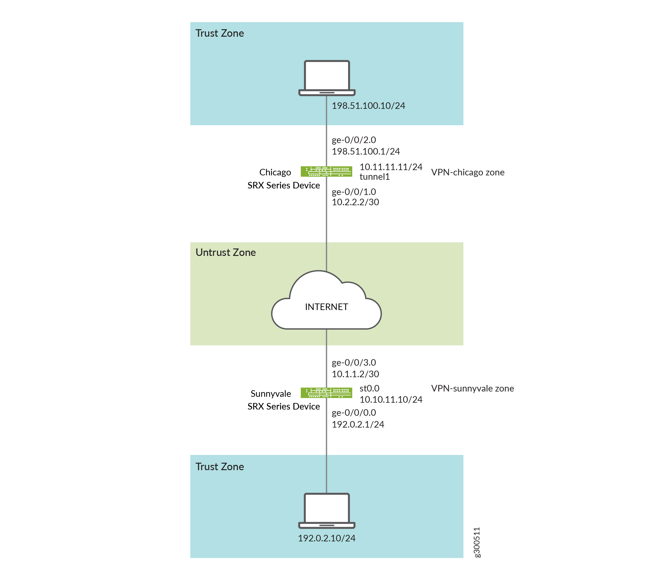
In this example, you configure an IPsec route-based VPN for a branch office in Chicago, because you do not need to conserve tunnel resources or configure many security policies to filter traffic through the tunnel. Users in the Chicago office will use the VPN to connect to their corporate headquarters in Sunnyvale.
Figure 1 shows an example of an IPsec route-based VPN topology. In this topology, one SRX Series Firewall is located in Sunnyvale, and one SRX Series Firewall is located in Chicago.
In this example, you configure interfaces, an IPv4 default route and security zones. Then you configure IKE, IPsec, a security policy, and CoS parameters. See Table 1 through Table 4.
Feature | Name | Configuration Parameters |
|---|---|---|
Interfaces | ge-0/0/0.0 | 192.0.2.1/24 |
ge-0/0/3.0 | 10.1.1.2/30 | |
st0.0 (tunnel interface) | 10.10.11.10/24 | |
Static routes | 0.0.0.0/0 (default route) | The next hop is st0.0. |
Security zones | trust |
|
untrust |
| |
vpn | The st0.0 interface is bound to this zone. |
Feature | Name | Configuration Parameters |
|---|---|---|
Proposal | ike-proposal |
|
Policy | ike-policy |
|
Gateway | gw-sunnyvale |
|
Feature | Name | Configuration Parameters |
|---|---|---|
Proposal | ipsec_prop |
|
Policy | ipsec_pol |
|
VPN | ipsec_vpn1 |
|
Purpose | Name | Configuration Parameters |
|---|---|---|
The security policy permits traffic from the trust zone to the vpn zone. | vpn |
|
The security policy permits traffic from the vpn zone to the trust zone. | vpn |
|
Configuration
- Configuring Basic Network and Security Zone Information
- Configuring CoS
- Configuring IKE
- Configuring IPsec
- Configuring Security Policies
Configuring Basic Network and Security Zone Information
CLI Quick Configuration
To quickly configure this example, copy the
following commands, paste them into a text file, remove any line breaks,
change any details necessary to match your network configuration,
copy and paste the commands into the CLI at the [edit] hierarchy
level, and then enter commit from configuration mode.
set interfaces ge-0/0/0 unit 0 family inet address 192.0.2.1/24
set interfaces ge-0/0/3 unit 0 family inet address 10.1.1.2/30
set interfaces st0 unit 0 family inet address 10.10.11.10/24
set routing-options static route 0.0.0.0/0 next-hop st0.0
set security zones security-zone untrust interfaces ge-0/0/3.0
set security zones security-zone untrust host-inbound-traffic system-services ike
set security zones security-zone trust interfaces ge-0/0/0.0
set security zones security-zone trust host-inbound-traffic system-services all
set security zones security-zone vpn-chicago interfaces st0.0
set security zones security-zone vpn-chicago host-inbound-traffic protocols all
set security zones security-zone vpn-chicago host-inbound-traffic system-services all
set security zones security-zone trust host-inbound-traffic protocols all
set security zones security-zone untrust host-inbound-traffic protocols all
Step-by-Step Procedure
The following example requires you to navigate various levels in the configuration hierarchy. For instructions on how to do that, see Using the CLI Editor in Configuration Mode in the CLI User Guide.
To configure interface, static route, and security zone information:
Configure Ethernet interface information.
content_copy zoom_out_map[edit] user@host# set interfaces ge-0/0/0 unit 0 family inet address 192.0.2.1/24 user@host# set interfaces ge-0/0/3 unit 0 family inet address 10.1.1.2/30 user@host# set interfaces st0 unit 0 family inet address 10.10.11.10/24
Configure static route information.
content_copy zoom_out_map[edit] user@host# set routing-options static route 0.0.0.0/0 next-hop st0.0
Configure the untrust security zone.
content_copy zoom_out_map[edit ] user@host# edit security zones security-zone untrust
Specify allowed system services for the untrust security zone.
content_copy zoom_out_map[edit security zones security-zone untrust] user@host# set host-inbound-traffic protocols all
Assign an interface to the security zone.
content_copy zoom_out_map[edit security zones security-zone untrust] user@host# set interfaces ge-0/0/3.0
Specify allowed system services for the security zone.
content_copy zoom_out_map[edit security zones security-zone untrust] user@host# set host-inbound-traffic system-services ike
Configure the trust security zone.
content_copy zoom_out_map[edit] user@host# edit security zones security-zone trust
Assign an interface to the trust security zone.
content_copy zoom_out_map[edit security zones security-zone trust] user@host# set interfaces ge-0/0/0.0
Specify allowed system services for the trust security zone.
content_copy zoom_out_map[edit security zones security-zone trust] user@host# set host-inbound-traffic system-services all user@host# set host-inbound-traffic protocols all
Configure the vpn security zone.
content_copy zoom_out_map[edit] user@host# edit security zones security-zone vpn
Assign an interface to the security zone.
content_copy zoom_out_map[edit security zones security-zone vpn-chicago] user@host# set interfaces st0.0 user@host# set host-inbound-traffic protocols all user@host# set host-inbound-traffic system-services all
Results
From configuration mode, confirm your configuration
by entering the show interfaces, show routing-options, and show security zones commands. If the output does
not display the intended configuration, repeat the configuration instructions
in this example to correct it.
[edit]
user@host# show interfaces
ge-0/0/0 {
    unit 0 {
        family inet {
            address 192.0.2.1/24;
        }
    }
}
ge-0/0/3 {
    unit 0 {
        family inet {
            address 10.1.1.2/30;
        }
    }
}
st0 {
    unit 0 {
        family inet {
        address 10.10.11.10/24;
        }
    }
}
[edit]
user@host# show routing-options
static {
    route 0.0.0.0/0 next-hop st0.0;
}
[edit]
user@host# show security zones
security-zone untrust {
    host-inbound-traffic {
        system-services {
            ike;
        }
        protocols {
            all;
        }
    }
    interfaces {
        ge-0/0/3.0;
    }
}
security-zone trust {
    host-inbound-traffic {
        system-services {
            all;
        }
        protocols {
            all;
        }
    }
    interfaces {
        ge-0/0/0.0;
    }
}
security-zone vpn-chicago {
    host-inbound-traffic {
        system-services {
            all;
        }
        protocols {
            all;
        }
    }
    interfaces {
        st0.0;
    }
}
If you are done configuring the device, enter commit from configuration mode.
Configuring CoS
CLI Quick Configuration
To quickly configure this example, copy the
following commands, paste them into a text file, remove any line breaks,
change any details necessary to match your network configuration,
copy and paste the commands into the CLI at the [edit] hierarchy
level, and then enter commit from configuration mode.
set class-of-service classifiers dscp ba-classifier import default
set class-of-service classifiers dscp ba-classifier forwarding-class best-effort loss-priority high code-points 000000
set class-of-service classifiers dscp ba-classifier forwarding-class ef-class loss-priority high code-points 000001
set class-of-service classifiers dscp ba-classifier forwarding-class af-class loss-priority high code-points 001010
set class-of-service classifiers dscp ba-classifier forwarding-class network-control loss-priority high code-points 000011
set class-of-service classifiers dscp ba-classifier forwarding-class res-class loss-priority high code-points 000100
set class-of-service classifiers dscp ba-classifier forwarding-class web-data loss-priority high code-points 000101
set class-of-service classifiers dscp ba-classifier forwarding-class control-data loss-priority high code-points 000111
set class-of-service classifiers dscp ba-classifier forwarding-class voip-data loss-priority high code-points 000110
set class-of-service forwarding-classes queue 7 voip-data
set class-of-service forwarding-classes queue 6 control-data
set class-of-service forwarding-classes queue 5 web-data
set class-of-service forwarding-classes queue 4 res-class
set class-of-service forwarding-classes queue 2 af-class
set class-of-service forwarding-classes queue 1 ef-class
set class-of-service forwarding-classes queue 0 best-effort
set class-of-service forwarding-classes queue 3 network-control
set class-of-service interfaces ge-0/0/3 unit 0 classifiers dscp ba-classifier
set class-of-service interfaces ge-0/0/3 unit 0 scheduler-map sched_1
set class-of-service scheduler-maps sched_1 forwarding-class voip-data scheduler Q7
set class-of-service scheduler-maps sched_1 forwarding-class control-data scheduler Q6
set class-of-service scheduler-maps sched_1 forwarding-class web-data scheduler Q5
set class-of-service scheduler-maps sched_1 forwarding-class res-class scheduler Q4
set class-of-service scheduler-maps sched_1 forwarding-class af-class scheduler Q2
set class-of-service scheduler-maps sched_1 forwarding-class ef-class scheduler Q1
set class-of-service scheduler-maps sched_1 forwarding-class best-effort scheduler Q0
set class-of-service scheduler-maps sched_1 forwarding-class network-control scheduler Q3
set class-of-service schedulers Q7 transmit-rate percent 5
set class-of-service schedulers Q7 priority strict-high
set class-of-service schedulers Q6 transmit-rate percent 25
set class-of-service schedulers Q6 priority high
set class-of-service schedulers Q5 transmit-rate remainder
set class-of-service schedulers Q5 priority high
set class-of-service schedulers Q4 transmit-rate percent 25
set class-of-service schedulers Q4 priority medium-high
set class-of-service schedulers Q3 transmit-rate remainder
set class-of-service schedulers Q3 priority medium-high
set class-of-service schedulers Q2 transmit-rate percent 10
set class-of-service schedulers Q2 priority medium-low
set class-of-service schedulers Q1 transmit-rate percent 10
set class-of-service schedulers Q1 priority medium-low
set class-of-service schedulers Q0 transmit-rate remainder
set class-of-service schedulers Q0 priority low
Step-by-Step Procedure
The following example requires you to navigate various levels in the configuration hierarchy. For instructions on how to do that, see Using the CLI Editor in Configuration Mode in the CLI User Guide.
To configure CoS:
Configure behavior aggregate classifiers for DiffServ CoS.
content_copy zoom_out_map[edit class-of-service] user@host# edit classifiers dscp ba-classifier user@host# set import default
Configure a best-effort forwarding class classifier.
content_copy zoom_out_map[edit class-of-service classifiers dscp ba-classifier] user@host# set forwarding-class best-effort loss-priority high code-points 000000
Define the DSCP value to be assigned to the forwarding class.
content_copy zoom_out_map[edit class-of-service classifiers dscp ba-classifier] user@host# set forwarding-class ef-class loss-priority high code-points 000001 user@host# set forwarding-class af-class loss-priority high code-points 001010 user@host# set forwarding-class network-control loss-priority high code-points 000011 user@host# set forwarding-class res-class loss-priority high code-points 000100 user@host# set forwarding-class web-data loss-priority high code-points 000101 user@host# set forwarding-class control-data loss-priority high code-points 000111 user@host# set forwarding-class voip-data loss-priority high code-points 000110
Define eight forwarding classes (queue names) for the eight queues.
content_copy zoom_out_map[edit class-of-service forwarding-classes] user@host# set queue 7 voip-data user@host# set queue 6 control-data user@host# set queue 5 web-data user@host# set queue 4 res-class user@host# set queue 2 af-class user@host# set queue 1 ef-class user@host# set queue 0 best-effort user@host# set queue 3 network-control
Configure classifiers on the ingress (ge) interfaces.
content_copy zoom_out_map[edit class-of-service] user@host# set interfaces ge-0/0/3 unit 0 classifiers dscp ba-classifier
Apply the scheduler map to the ge interface.
content_copy zoom_out_map[edit class-of-service] user@host# set interfaces ge-0/0/3 unit 0 scheduler-map sched_1
Configure the scheduler map to associate schedulers with defined forwarding classes.
content_copy zoom_out_map[edit class-of-service] user@host# set scheduler-maps sched_1 forwarding-class voip-data scheduler Q7 user@host# set scheduler-maps sched_1 forwarding-class control-data scheduler Q6 user@host# set scheduler-maps sched_1 forwarding-class web-data scheduler Q5 user@host# set scheduler-maps sched_1 forwarding-class res-class scheduler Q4 user@host# set scheduler-maps sched_1 forwarding-class af-class scheduler Q2 user@host# set scheduler-maps sched_1 forwarding-class ef-class scheduler Q1 user@host# set scheduler-maps sched_1 forwarding-class best-effort scheduler Q0 user@host# set scheduler-maps sched_1 forwarding-class network-control scheduler Q3
Define the schedulers with priority and transmit rates.
content_copy zoom_out_map[edit set class-of-service] user@host# set schedulers Q7 transmit-rate percent 5 user@host# set schedulers Q7 priority strict-high user@host# set schedulers Q6 transmit-rate percent 25 user@host# set schedulers Q6 priority high user@host# set schedulers Q5 transmit-rate remainder user@host# set schedulers Q5 priority high user@host# set schedulers Q4 transmit-rate percent 25 user@host# set schedulers Q4 priority medium-high user@host# set schedulers Q3 transmit-rate remainder user@host# set schedulers Q3 priority medium-high user@host# set schedulers Q2 transmit-rate percent 10 user@host# set schedulers Q2 priority medium-low user@host# set schedulers Q1 transmit-rate percent 10 user@host# set schedulers Q1 priority medium-low user@host# set schedulers Q0 transmit-rate remainder user@host# set schedulers Q0 priority low
Results
From configuration mode, confirm your configuration
by entering the show class-of-service command. If the output
does not display the intended configuration, repeat the configuration
instructions in this example to correct it.
[edit]
user@host# show class-of-service
classifiers {
    dscp ba-classifier {
        import default;
        forwarding-class best-effort {
            loss-priority high code-points 000000;
        }
        forwarding-class ef-class {
            loss-priority high code-points 000001;
        }
        forwarding-class af-class {
            loss-priority high code-points 001010;
        }
        forwarding-class network-control {
            loss-priority high code-points 000011;
        }
        forwarding-class res-class {
            loss-priority high code-points 000100;
        }
        forwarding-class web-data {
            loss-priority high code-points 000101;
        }
        forwarding-class control-data {
            loss-priority high code-points 000111;
        }
        forwarding-class voip-data {
            loss-priority high code-points 000110;
        }
    }
}
forwarding-classes {
    queue 7 voip-data;
    queue 6 control-data;
    queue 5 web-data;
    queue 4 res-class;
    queue 2 af-class;
    queue 1 ef-class;
    queue 0 best-effort;
    queue 3 network-control;
}
interfaces {
    ge-0/0/3 {
        unit 0 {
            classifiers {
                dscp ba-classifier;
            }
        }
    }
    ge-0/0/3 {
        unit 0 {
            scheduler-map sched_1;
        }
    }
}
scheduler-maps {
    sched_1 {
        forwarding-class voip-data scheduler Q7;
        forwarding-class control-data scheduler Q6;
        forwarding-class web-data scheduler Q5;
        forwarding-class res-class scheduler Q4;
        forwarding-class af-class scheduler Q2;
        forwarding-class ef-class scheduler Q1;
        forwarding-class best-effort scheduler Q0;
        forwarding-class network-control scheduler Q3;
    }
}
schedulers {
    Q7 {
        transmit-rate percent 5;
        priority strict-high;
    }
    Q6 {
        transmit-rate percent 25;
        priority high;
    }
    Q5 {
        transmit-rate {
            remainder;
        }
        priority high;
    }
    Q4 {
        transmit-rate percent 25;
        priority medium-high;
    }
    Q3 {
        transmit-rate {
            remainder;
        }
        priority medium-high;
    }
    Q2 {
        transmit-rate percent 10;
        priority medium-low;
    }
    Q1 {
        transmit-rate percent 10;
        priority medium-low;
    }
    Q0 {
        transmit-rate {
            remainder;
        }
        priority low;
    }
}
If you are done configuring the device, enter commit from configuration mode.
Configuring IKE
CLI Quick Configuration
To quickly configure this example, copy the
following commands, paste them into a text file, remove any line breaks,
change any details necessary to match your network configuration,
copy and paste the commands into the CLI at the [edit] hierarchy
level, and then enter commit from configuration mode.
set security ike proposal ike-proposal authentication-method pre-shared-keys
set security ike proposal ike-proposal dh-group group14
set security ike proposal ike-proposal authentication-algorithm sha-256
set security ike proposal ike-proposal encryption-algorithm aes-256-cbc
set security ike policy ike-policy mode main
set security ike policy ike-policy proposals ike-proposal
set security ike policy ike-policy pre-shared-key ascii-text $ABC123
set security ike gateway gw-sunnyvale external-interface ge-0/0/3.0
set security ike gateway gw-sunnyvale ike policy ike-policy
set security ike gateway gw-sunnyvale address 10.2.2.2
set security ike gateway gw-sunnyvale version v2-only
Step-by-Step Procedure
The following example requires you to navigate various levels in the configuration hierarchy. For instructions on how to do that, see Using the CLI Editor in Configuration Mode in the CLI User Guide.
To configure IKE:
Create the IKE proposal.
content_copy zoom_out_map[edit security ike] user@host# set proposal ike-proposal
Define the IKE proposal authentication method.
content_copy zoom_out_map[edit security ike proposal ike-proposal] user@host# set authentication-method pre-shared-keys
Define the IKE proposal Diffie-Hellman group.
content_copy zoom_out_map[edit security ike proposal ike-proposal] user@host# set dh-group group14
Define the IKE proposal authentication algorithm.
content_copy zoom_out_map[edit security ike proposal ike-proposal] user@host# set authentication-algorithm sha-256
Define the IKE proposal encryption algorithm.
content_copy zoom_out_map[edit security ike proposal ike-proposal] user@host# set encryption-algorithm aes-256-cbc
Create an IKE policy.
content_copy zoom_out_map[edit security ike] user@host# set policy ike-policy
Set the IKE policy mode.
content_copy zoom_out_map[edit security ike policy ike-policy] user@host# set mode main
Specify a reference to the IKE proposal.
content_copy zoom_out_map[edit security ike policy ike-policy] user@host# set proposals ike-proposal
Define the IKE policy authentication method.
content_copy zoom_out_map[edit security ike policy ike-policy] user@host# set pre-shared-key ascii-text $ABC123
Create an IKE gateway and define its external interface.
content_copy zoom_out_map[edit security ike] user@host# set gateway gw-sunnyvale external-interface ge-0/0/3.0
Define the IKE policy reference.
content_copy zoom_out_map[edit security ike gateway gw-sunnyvale] user@host# set ike policy ike-policy
Define the IKE gateway address.
content_copy zoom_out_map[edit security ike gateway gw-sunnyvale] user@host# set address 10.2.2.2
Define the IKE gateway version.
content_copy zoom_out_map[edit security ike gateway gw-sunnyvale] user@host# set version v2-only
Results
From configuration mode, confirm your configuration
by entering the show security ike command. If the output
does not display the intended configuration, repeat the configuration
instructions in this example to correct it.
[edit]
user@host# show security ike
proposal ike-proposal {
    authentication-method pre-shared-keys;
    dh-group group14;
    authentication-algorithm sha-256;
    encryption-algorithm aes-256-cbc;
}
policy ike-policy {
    mode main;
    proposals ike-proposal;
    pre-shared-key ascii-text "$ABC123";
}
gateway gw-sunnyvale {
    ike policy ike-policy;
    address 10.2.2.2;
    external-interface ge-0/0/3.0;
    version v2-only;
}
If you are done configuring the device, enter commit from configuration mode.
Configuring IPsec
CLI Quick Configuration
To quickly configure this example, copy the
following commands, paste them into a text file, remove any line breaks,
change any details necessary to match your network configuration,
copy and paste the commands into the CLI at the [edit] hierarchy
level, and then enter commit from configuration mode.
set security ipsec traceoptions flag all
set security ipsec proposal ipsec_prop protocol esp
set security ipsec proposal ipsec_prop authentication-algorithm hmac-sha-256
set security ipsec proposal ipsec_prop encryption-algorithm aes256-cbc
set security ipsec proposal ipsec_prop lifetime-seconds 3600
set security ipsec policy ipsec_pol proposals ipsec_prop
set security ipsec vpn ipsec_vpn1 bind-interface st0.0
set security ipsec vpn ipsec_vpn1 multi-sa forwarding-class ef-class
set security ipsec vpn ipsec_vpn1 multi-sa forwarding-class af-class
set security ipsec vpn ipsec_vpn1 multi-sa forwarding-class res-class
set security ipsec vpn ipsec_vpn1 multi-sa forwarding-class web-data
set security ipsec vpn ipsec_vpn1 multi-sa forwarding-class control-data
set security ipsec vpn ipsec_vpn1 multi-sa forwarding-class voip-data
set security ipsec vpn ipsec_vpn1 multi-sa forwarding-class network-control
set security ipsec vpn ipsec_vpn1 multi-sa forwarding-class best-effort
set security ipsec vpn ipsec_vpn1 ike gateway gw_sunnyvale
set security ipsec vpn ipsec_vpn1 ike ipsec-policy ipsec_pol
set security ipsec vpn ipsec_vpn1 establish-tunnels immediately
set security ipsec vpn ipsec_vpn1 traffic-selector ipsec_vpn1_TS1 local-ip 203.0.113.2/25
set security ipsec vpn ipsec_vpn1 traffic-selector ipsec_vpn1_TS1 remote-ip 192.0.2.30/24
Step-by-Step Procedure
The following example requires you to navigate various levels in the configuration hierarchy. For instructions on how to do that, see Using the CLI Editor in Configuration Mode in the CLI User Guide.
To configure IPsec:
Enable IPsec trace options.
content_copy zoom_out_map[edit] user@host# set security ipsec traceoptions flag all
Create an IPsec proposal.
content_copy zoom_out_map[edit] user@host# set security ipsec proposal ipsec_prop
Specify the IPsec proposal protocol.
content_copy zoom_out_map[edit security ipsec proposal ipsec_prop] user@host# set protocol esp
Specify the IPsec proposal authentication algorithm.
content_copy zoom_out_map[edit security ipsec proposal ipsec_prop] user@host# set authentication-algorithm hmac-sha-256
Specify the IPsec proposal encryption algorithm.
content_copy zoom_out_map[edit security ipsec proposal ipsec_prop] user@host# set encryption-algorithm aes256-cbc
Specify the lifetime (in seconds) of an IPsec security association (SA).
content_copy zoom_out_map[set security ipsec proposal ipsec_prop] user@host# set lifetime-seconds 3600
Create the IPsec policy.
content_copy zoom_out_map[edit security ipsec] user@host# set policy ipsec_pol
Specify the IPsec proposal reference.
content_copy zoom_out_map[edit security ipsec policy ipsec_pol] user@host# set proposals ipsec_prop
Specify the interface to bind.
content_copy zoom_out_map[edit security ipsec] user@host# set vpn ipsec_vpn1 bind-interface st0.0
Configure the forwarding class to the multiple IPsec SA.
content_copy zoom_out_map[edit security ipsec] user@host# set vpn ipsec_vpn1 multi-sa forwarding-class ef-class user@host# set vpn ipsec_vpn1 multi-sa forwarding-class af-class user@host# set vpn ipsec_vpn1 multi-sa forwarding-class res-class user@host# set vpn ipsec_vpn1 multi-sa forwarding-class web-data user@host# set vpn ipsec_vpn1 multi-sa forwarding-class control-data user@host# set vpn ipsec_vpn1 multi-sa forwarding-class voip-data user@host# set vpn ipsec_vpn1 multi-sa forwarding-class network-control user@host# set vpn ipsec_vpn1 multi-sa forwarding-class best-effort
Specify the IKE gateway.
content_copy zoom_out_map[edit security ipsec] user@host# set vpn ipsec_vpn1 ike gateway gw_sunnyvale
Specify the IPsec policies.
content_copy zoom_out_map[edit security ipsec] user@host# set vpn ipsec_vpn1 ike ipsec-policy ipsec_pol
Specify that the tunnel be brought up immediately to negotiate IPsec SA when the first data packet arrives to be sent.
content_copy zoom_out_map[edit security ipsec] user@host# set vpn ipsec_vpn1 establish-tunnels immediately
Configure local IP addresses for a traffic selector.
content_copy zoom_out_map[edit security ipsec] user@host# set vpn ipsec_vpn1 traffic-selector ipsec_vpn1_TS1 local-ip 203.0.113.2/25
Configure remote IP addresses for a traffic selector.
content_copy zoom_out_map[edit security ipsec] user@host# set vpn ipsec_vpn1 traffic-selector ipsec_vpn1_TS1 remote-ip 192.0.2.30/24
Results
From configuration mode, confirm your configuration
by entering the show security ipsec command. If the output
does not display the intended configuration, repeat the configuration
instructions in this example to correct it.
[edit]
user@host# show security ipsec
traceoptions {
    flag all;
}
proposal ipsec_prop {
    protocol esp;
    authentication-algorithm hmac-sha-256;
    encryption-algorithm aes256-cbc;
}
proposal ipsec_prop {
    lifetime-seconds 3600;
}
policy ipsec_pol {
    proposals ipsec_prop;
}
vpn ipsec_vpn1 {
    bind-interface st0.0;
    multi-sa {
        forwarding-class ef-class;
        forwarding-class af-class;
        forwarding-class res-class;
        forwarding-class web-data;
        forwarding-class control-data;
        forwarding-class voip-data;
        forwarding-class network-control;
        forwarding-class best-effort;
    }
    ike {
        gateway gw_sunnyvale;
        ipsec-policy ipsec_pol;
    }
    traffic-selector ipsec_vpn1_TS1 {
        local-ip 203.0.113.2/25;
        remote-ip 192.0.2.30/24;
    }
    establish-tunnels immediately;
}
If you are done configuring the device, enter commit from configuration mode.
Configuring Security Policies
CLI Quick Configuration
To quickly configure this example, copy the
following commands, paste them into a text file, remove any line breaks,
change any details necessary to match your network configuration,
copy and paste the commands into the CLI at the [edit] hierarchy
level, and then enter commit from configuration mode.
set security policies from-zone trust to-zone vpn policy vpn match source-address sunnyvale
set security policies from-zone trust to-zone vpn policy vpn match destination-address chicago
set security policies from-zone trust to-zone vpn policy vpn match application any
set security policies from-zone trust to-zone vpn policy vpn then permit
set security policies from-zone vpn to-zone trust policy vpn match source-address chicago
set security policies from-zone vpn to-zone trust policy vpn match destination-address sunnyvale
set security policies from-zone vpn to-zone trust policy vpn match application any
set security policies from-zone vpn to-zone trust policy vpn then permit
Enable security policies trace options for troubleshooting the policy-related issues.
Step-by-Step Procedure
The following example requires you to navigate various levels in the configuration hierarchy. For instructions on how to do that, see Using the CLI Editor in Configuration Mode in the CLI User Guide.
To configure security policies:
Create the security policy to permit traffic from the trust zone to the vpn zone.
content_copy zoom_out_map[edit security policies from-zone trust to-zone vpn] user@host# set policy vpn match source-address sunnyvale user@host# set policy vpn match destination-address chicago user@host# set policy vpn match application any user@host# set policy vpn then permit
Create the security policy to permit traffic from the vpn zone to the trust zone.
content_copy zoom_out_map[edit security policies from-zone vpn to-zone trust] user@host# set policy vpn match source-address chicago user@host# set policy vpn match destination-address sunnyvale user@host# set policy vpn match application any user@host# set policy vpn then permit
Results
From configuration mode, confirm your configuration
by entering the show security policies command. If the
output does not display the intended configuration, repeat the configuration
instructions in this example to correct it.
[edit]
user@host# show security policies
from-zone trust to-zone vpn {
    policy vpn {
        match {
            source-address sunnyvale;
            destination-address chicago;
            application any;
        }
        then {
            permit;
        }
    }
}
from-zone vpn to-zone trust {
    policy vpn {
        match {
            source-address chicago;
            destination-address sunnyvale;
            application any;
        }
        then {
            permit;
        }
    }
}
If you are done configuring the device, enter commit from configuration mode.
Verification
Confirm that the configuration is working properly.
Verifying IPsec Security Associations
Purpose
Verify the IPsec status.
Action
From operational mode, enter the show security
ipsec security-associations command. After obtaining an index
number from the command, use the show security ipsec security-associations
index 131073 detail and show security
ipsec statistics index 131073 commands.
For brevity, the show command outputs does not display all the values of the configuration. Only a subset of the configuration is displayed. Rest of the configuration on the system has been replaced with ellipses (...).
user@host> show security ipsec security-associations
Total active tunnels: 2     Total Ipsec sas: 18
  ID    Algorithm       SPI      Life:sec/kb  Mon lsys Port  Gateway
  <131073 ESP:aes256/sha256 2d8e710b 1949/ unlim   -   root 500   5.0.0.1
  >131073 ESP:aes256/sha256 5f3a3239 1949/ unlim   -   root 500   5.0.0.1
  <131073 ESP:aes256/sha256 5d227e19 1949/ unlim   -   root 500   5.0.0.1
  >131073 ESP:aes256/sha256 5490da   1949/ unlim   -   root 500   5.0.0.1
  <131073 ESP:aes256/sha256 211fb8bc 1949/ unlim   -   root 500   5.0.0.1
  >131073 ESP:aes256/sha256 dde29cd0 1949/ unlim   -   root 500   5.0.0.1
  <131073 ESP:aes256/sha256 49b64080 1949/ unlim   -   root 500   5.0.0.1
  >131073 ESP:aes256/sha256 314afea0 1949/ unlim   -   root 500   5.0.0.1
  <131073 ESP:aes256/sha256 fec6f6ea 1949/ unlim   -   root 500   5.0.0.1
  >131073 ESP:aes256/sha256 428a3a0d 1949/ unlim   -   root 500   5.0.0.1
...
user@host> show security ipsec security-associations index 131073 detail

ID: 131073 Virtual-system: root, VPN Name: IPSEC_VPN1
  Local Gateway: 4.0.0.1, Remote Gateway: 5.0.0.1
  Local Identity: ipv4_subnet(any:0,[0..7]=0.0.0.0/0)
  Remote Identity: ipv4_subnet(any:0,[0..7]=0.0.0.0/0)
  Version: IKEv2
  DF-bit: clear, Copy-Outer-DSCP Disabled, Bind-interface: st0.0
  Port: 500, Nego#: 18, Fail#: 0, Def-Del#: 0 Flag: 0x600a39
  Multi-sa, Configured SAs# 9, Negotiated SAs#: 9
  Tunnel events:
    Mon Apr 23 2018 22:20:54 -0700: IPSec SA negotiation successfully completed (1 times)
    Mon Apr 23 2018 22:20:54 -0700: IKE SA negotiation successfully completed (2 times)
    Mon Apr 23 2018 22:20:18 -0700: User cleared IKE SA from CLI, corresponding IPSec SAs cleared (1 times)
    Mon Apr 23 2018 22:19:55 -0700: IPSec SA negotiation successfully completed (2 times)
    Mon Apr 23 2018 22:19:23 -0700: Tunnel is ready. Waiting for trigger event or peer to trigger negotiation (1 times)
    Mon Apr 23 2018 22:19:23 -0700: Bind-interface's zone received. Information updated (1 times)
    Mon Apr 23 2018 22:19:23 -0700: External interface's zone received. Information updated (1 times)
  Direction: inbound, SPI: 2d8e710b, AUX-SPI: 0
                              , VPN Monitoring: -
    Hard lifetime: Expires in 1930 seconds
    Lifesize Remaining:  Unlimited
    Soft lifetime: Expires in 1563 seconds
    Mode: Tunnel(0 0), Type: dynamic, State: installed
    Protocol: ESP, Authentication: hmac-sha-256, Encryption: aes-256-cbc
    Anti-replay service: counter-based enabled, Replay window size: 64
    Multi-sa FC Name: default
  Direction: outbound, SPI: 5f3a3239, AUX-SPI: 0
                              , VPN Monitoring: -
    Hard lifetime: Expires in 1930 seconds
    Lifesize Remaining:  Unlimited
    Soft lifetime: Expires in 1563 seconds
    Mode: Tunnel(0 0), Type: dynamic, State: installed
    Protocol: ESP, Authentication: hmac-sha-256, Encryption: aes-256-cbc
    Anti-replay service: counter-based enabled, Replay window size: 64
    Multi-sa FC Name: default
  Direction: inbound, SPI: 5d227e19, AUX-SPI: 0
                              , VPN Monitoring: -
    Hard lifetime: Expires in 1930 seconds
    Lifesize Remaining:  Unlimited
    Soft lifetime: Expires in 1551 seconds
    Mode: Tunnel(0 0), Type: dynamic, State: installed
    Protocol: ESP, Authentication: hmac-sha-256, Encryption: aes-256-cbc
    Anti-replay service: counter-based enabled, Replay window size: 64
    Multi-sa FC Name: best-effort
  Direction: outbound, SPI: 5490da, AUX-SPI: 0
                              , VPN Monitoring: -
    Hard lifetime: Expires in 1930 seconds
    Lifesize Remaining:  Unlimited
    Soft lifetime: Expires in 1551 seconds
    Mode: Tunnel(0 0), Type: dynamic, State: installed
    Protocol: ESP, Authentication: hmac-sha-256, Encryption: aes-256-cbc
    Anti-replay service: counter-based enabled, Replay window size: 64
...user@host> show security ipsec statistics index 131073 ESP Statistics: Encrypted bytes: 952 Decrypted bytes: 588 Encrypted packets: 7 Decrypted packets: 7 AH Statistics: Input bytes: 0 Output bytes: 0 Input packets: 0 Output packets: 0 Errors: AH authentication failures: 0, Replay errors: 0 ESP authentication failures: 0, ESP decryption failures: 0 Bad headers: 0, Bad trailers: 0 FC Name Encrypted Pkts Decrypted Pkts Encrypted bytes Decrypted bytes best-effort 7 7 952 588 custom_q1 0 0 0 0 custom_q2 0 0 0 0 network-control 0 0 0 0 custom_q4 0 0 0 0 custom_q5 0 0 0 0 custom_q6 0 0 0 0 custom_q7 0 0 0 0 default 0 0 0 0
Meaning
The output from the show security ipsec security-associations command lists the following information:
The ID number is 131073. Use this value with the show security ipsec security-associations index command to get more information about this particular SA.
There is one IPsec SA pair using port 500.
The SPIs, lifetime (in seconds), and usage limits (or lifesize in KB) are shown for both directions. The 1949/ unlim value indicates that the Phase lifetime expires in 1949 seconds, and that no lifesize has been specified, which indicates that it is unlimited.
VPN monitoring is not enabled for this SA, as indicated by a hyphen in the Mon column. If VPN monitoring is enabled, U indicates that monitoring is up, and D indicates that monitoring is down.
The show security ike security-associations index 131073
detail command lists additional information about the SA with
an index number of 131073:
The local identity and remote identity make up the proxy ID for the SA. A proxy ID mismatch is one of the most common causes for a Phase failure. If no IPsec SA is listed, confirm that Phase proposals, including the proxy ID settings, are correct for both peers.
Displays all the child SA details including forwarding class name.
The show security ipsec statistics index 131073 command
lists statistics for each forwarding class name.
An error value of zero in the output indicates a normal condition.
We recommend running this command multiple times to observe any packet loss issues across a VPN. Output from this command also displays the statistics for encrypted and decrypted packet counters, error counters, and so on.
You must enable security flow trace options to investigate which ESP packets are experiencing errors and why.
Understand CoS Support on st0 Interfaces
Starting with Junos OS Release 15.1X49-D60 and Junos OS Release 17.3R1, class of service (CoS) features such as classifier, policer, queuing, scheduling, shaping, rewriting markers, and virtual channels can now be configured on the secure tunnel interface (st0) for point-to-point VPNs.
The st0 tunnel interface is an internal interface that can be used by route-based VPNs to route cleartext traffics to an IPsec VPN tunnel. The following CoS features are supported on the st0 interface on all available SRX Series Firewalls and vSRX2.0:
Classifiers
Policers
Queuing, scheduling, and shaping
Rewrite markers
Virtual channels
Starting with Junos OS Release 15.1X49-D70 and Junos OS Release 17.3R1, support for queuing, scheduling, shaping, and virtual channels is added to the st0 interface for SRX5400, SRX5600, and SRX5800 devices. Support for all the listed CoS features is added for the st0 interface for SRX1500, SRX4100, and SRX4200 devices. Starting with Junos OS Release 17.4R1, support for listed CoS features is added for the st0 interface for SRX4600 devices.
Limitations of CoS support on VPN st0 interfaces
The following limitations apply to CoS support on VPN st0 interfaces:
The maximum number for software queues is 2048. If the number of st0 interfaces exceeds 2048, not enough software queues can be created for all the st0 interfaces.
Only route-based VPNs can apply CoS features on st0 interfaces. Table 5 describes the st0 CoS feature support for different types of VPNs.
Table 5: CoS Feature Support for VPN Classifier Features Site-to-Site VPN (P2P) AutoVPN (P2P) Site-to-Site/Auto VPN /AD-VPN (P2MP) Classifiers, policers, and rewriting markers
Supported
Supported
Supported
Queueing, scheduling, and shaping based on st0 logical interfaces
Supported
Not supported
Not supported
Queueing, scheduling, and shaping based on virtual channels
Supported
Supported
Supported
On SRX300, SRX320, SRX340, SRX345, and SRX550HM devices, one st0 logical interface can bind to multiple VPN tunnels. The eight queues for the st0 logical interface cannot reroute the traffic to different tunnels, so pre-tunneling is not supported.
The virtual channel feature can be used as a workaround on SRX300, SRX320, SRX340, SRX345, and SRX550HM devices.
When defining a CoS shaping rate on an st0 tunnel interface, consider the following restrictions:
The shaping rate on the tunnel interface must be less than that of the physical egress interface.
The shaping rate only measures the packet size that includes the inner Layer 3 cleartext packet with an ESP/AH header and an outer IP header encapsulation. The outer Layer 2 encapsulation added by the physical interface is not factored into the shaping rate measurement.
The CoS behavior works as expected when the physical interface carries the shaped GRE or IP-IP tunnel traffic only. If the physical interface carries other traffic, thereby lowering the available bandwidth for tunnel interface traffic, the CoS features do not work as expected.
On SRX550M, SRX5400, SRX5600, and SRX5800 devices, bandwidth limit and burst size limit values in a policer configuration are a per-SPU, not per-system limitation. This is the same policer behavior as on the physical interface.
See Also
Change History Table
Feature support is determined by the platform and release you are using. Use Feature Explorer to determine if a feature is supported on your platform.
