IPsec VPN Tunnels with Chassis Clusters
Juniper Networks supports IPsec VPN tunnels in a chassis cluster setup. In an active/passive chassis cluster on the firewalls, all VPN tunnels terminate on the same node. In an active/active chassis cluster, VPN tunnels can terminate on either node.
Understanding Dual Active-Backup IPsec VPN Chassis Clusters
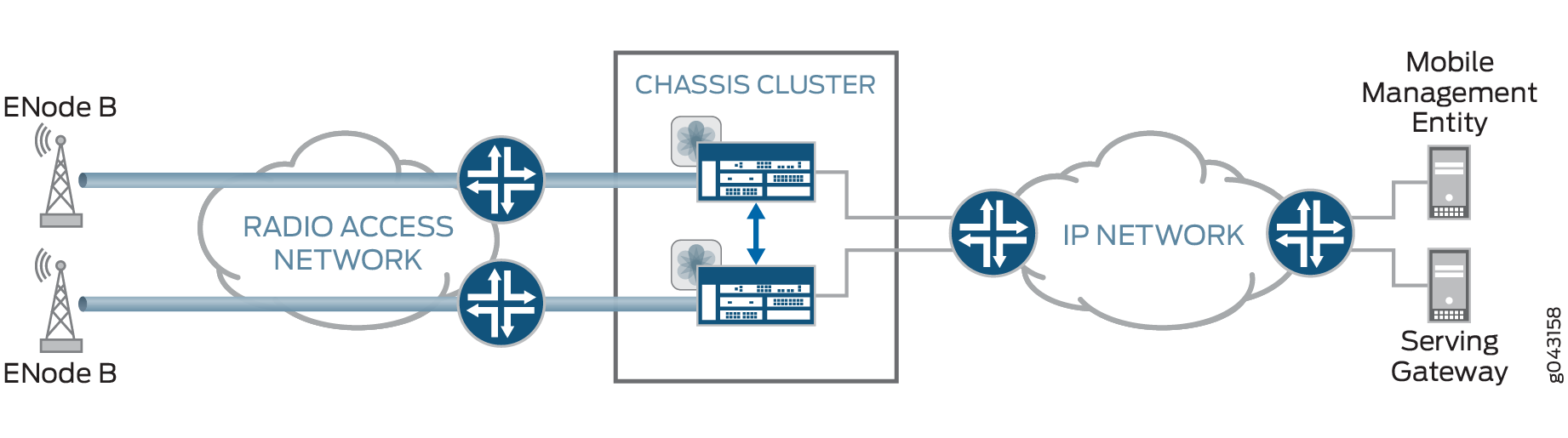
In an active/passive chassis cluster, all VPN tunnels terminate on the same node, as shown in Figure 1.
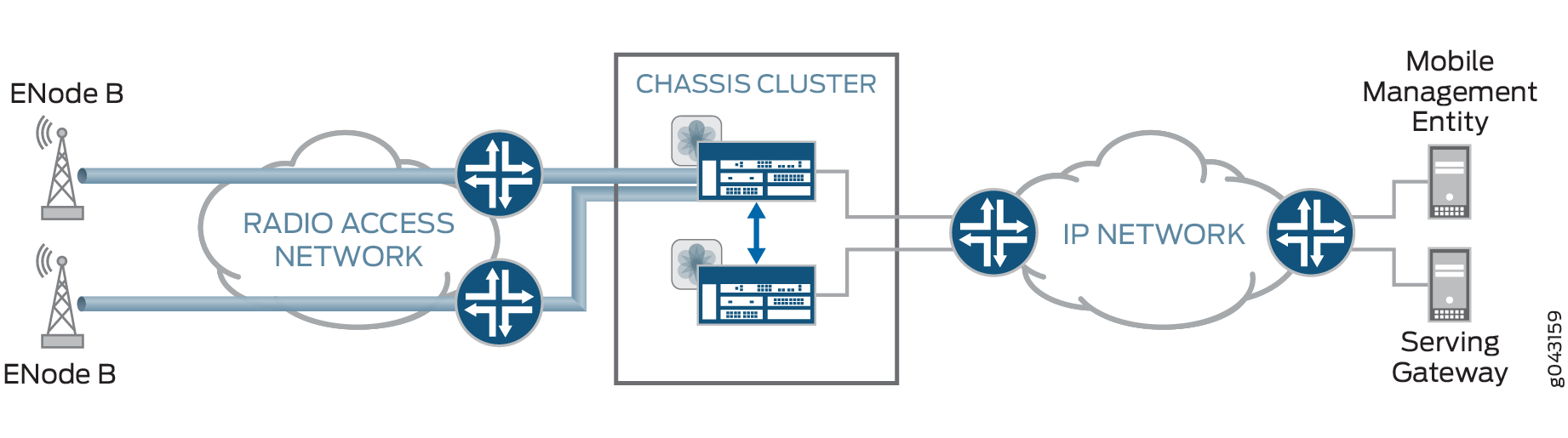
In an active/active chassis cluster, VPN tunnels can terminate on either node. Both nodes in the chassis cluster can actively pass traffic through VPN tunnels on both nodes at the same time, as shown in Figure 2. This deployment is known as dual active-backup IPsec VPN chassis clusters.
The following features are supported with dual active-backup IPsec VPN chassis clusters:
-
Route-based VPNs only. Policy-based VPNs are not supported.
-
IKEv1 and IKEv2.
-
Digital certificate or preshared key authentication.
-
IKE and secure tunnel interfaces (st0) in virtual routers.
-
Network Address Translation-Traversal (NAT-T).
-
VPN monitoring.
-
Dead peer detection.
-
In-service software upgrade (ISSU).
-
Insertion of Services Processing Cards (SPCs) on a chassis cluster device without disrupting the traffic on the existing VPN tunnels. See VPN Support for Inserting Services Processing Cards.
-
Dynamic routing protocols.
-
Secure tunnel interfaces (st0) configured in point-to-multipoint mode.
-
AutoVPN with st0 interfaces in point-to-point mode with traffic selectors.
-
IPv4-in-IPv4, IPv6-in-IPv4, IPv6-in-IPv6 and IPv4-in-IPv6 tunnel modes.
-
Fragmented traffic.
-
The loopback interface can be configured as the external interface for the VPN.
Dual active-backup IPsec VPN chassis clusters cannot be configured with Z-mode flows. Z-mode flows occur when traffic enters an interface on a chassis cluster node, passes through the fabric link, and exits through an interface on the other cluster node.
See Also
Example: Configuring Redundancy Groups for Loopback Interfaces
This example shows how to configure a redundancy group (RG) for a loopback interface in order to prevent VPN failure. Redundancy groups are used to bundle interfaces into a group for failover purpose in a chassis cluster setup.
Requirements
This example uses the following hardware and software:
A pair of firewalls that support chassis cluster
An SSG140 device or equivalent
Two switches
Supported Junos OS Release for the firewalls
Before you begin:
Understand chassis cluster redundant Ethernet interfaces. See Chassis Cluster User Guide for Firewalls.
Overview
An Internet Key Exchange (IKE) gateway needs an external interface to communicate with a peer device. In a chassis cluster setup, the node on which the external interface is active selects a Services Processing Unit (SPU) to support the VPN tunnel. IKE and IPsec packets are processed on that SPU. Therefore, the active external interface decides the anchor SPU.
In a chassis cluster setup, the external interface is a redundant Ethernet interface. A redundant Ethernet interface can go down when its physical (child) interfaces are down. You can configure a loopback interface as an alternative physical interface to reach the peer gateway. Loopback interfaces can be configured on any redundancy group. This redundancy group configuration is only checked for VPN packets, because only VPN packets must find the anchor SPU through the active interface.
You must configure lo0.x in a custom virtual router, since lo0.0 is in the default virtual router and only one loopback interface is allowed in a virtual router.
Figure 3 shows an example of a loopback chassis cluster VPN topology. In this topology, the firewall chassis cluster device is located in Sunnyvale, California. The chassis cluster device works as a single gateway in this setup. The SSG Series device (or a third-party device) is located in Chicago, Illinois. This device acts as a peer device to the firewall chassis cluster and it helps to build a VPN tunnel.
Configuration
Procedure
CLI Quick Configuration
To quickly configure this section of the example,
copy the following commands, paste them into a text file, remove any
line breaks, change any details necessary to match your network configuration,
copy and paste the commands into the CLI at the [edit] hierarchy
level, and then enter commit from configuration
mode.
set interfaces lo0 redundant-pseudo-interface-options redundancy-group 1
set interfaces lo0 unit 1 family inet address 10.3.3.3/30
set routing-instances vr1 instance-type virtual-router
set routing-instances vr1 interface lo0.1
set routing-instances vr1 interface reth0.0
set routing-instances vr1 interface reth1.0
set routing-instances vr1 interface st0.0
set routing-instances vr1 routing-options static route 192.168.168.1/24 next-hop st0.0
set security ike policy ike-policy1 mode main
set security ike policy ike-policy1 proposal-set standard
set security ike policy ike-policy1 pre-shared-key ascii-text "$ABC123"
set security ike gateway t-ike-gate ike-policy ike-policy1
set security ike gateway t-ike-gate address 10.2.2.2
set security ike gateway t-ike-gate external-interface lo0.1
set security ipsec proposal p2-std-p1 authentication-algorithm hmac-sha1-96
set security ipsec proposal p2-std-p1 encryption-algorithm 3des-cbc
set security ipsec proposal p2-std-p1 lifetime-seconds 180
set security ipsec proposal p2-std-p2 authentication-algorithm hmac-sha1-96
set security ipsec proposal p2-std-p2 encryption-algorithm aes-128-cbc
set security ipsec proposal p2-std-p2 lifetime-seconds 180
set security ipsec policy vpn-policy1 perfect-forward-secrecy keys group2
set security ipsec policy vpn-policy1 proposals p2-std-p1
set security ipsec policy vpn-policy1 proposals p2-std-p2
set security ipsec vpn t-ike-vpn bind-interface st0.0
set security ipsec vpn t-ike-vpn ike gateway t-ike-gate
set security ipsec vpn t-ike-vpn ike proxy-identity local 10.10.10.1/24
set security ipsec vpn t-ike-vpn ike proxy-identity remote 192.168.168.1/24
set security ipsec vpn t-ike-vpn ike ipsec-policy vpn-policy1
Step-by-Step Procedure
To configure a redundancy group for a loopback interface:
Configure the loopback interface in one redundancy group.
[edit interfaces]
user@host# set lo0 redundant-pseudo-interface-options redundancy-group 1
Configure the IP address for the loopback interface.
[edit interfaces]
user@host# set lo0 unit 1 family inet address 10.3.3.3/30
Configure routing options.
[edit routing-instances]
user@host# set vr1 instance-type virtual-router
user@host# set vr1 interface lo0.1
user@host# set vr1 interface reth0.0
user@host# set vr1 interface reth1.0
user@host# set vr1 interface st0.0
user@host# set vr1 routing-options static route 192.168.168.1/24 next-hop st0.0
Configure the loopback interface as an external interface for the IKE gateway.
[edit security ike]
user@host# set policy ike-policy1 mode main
user@host# set policy ike-policy1 proposal-set standard
user@host# set policy ike-policy1 pre-shared-key ascii-text "$ABC123"
user@host# set gateway t-ike-gate ike-policy ike-policy1
user@host# set gateway t-ike-gate address 10.2.2.2
user@host# set gateway t-ike-gate external-interface lo0.1
Configure an IPsec proposal.
[edit security ipsec]
user@host# set proposal p2-std-p1 authentication-algorithm hmac-sha1-96
user@host# set proposal p2-std-p1 encryption-algorithm 3des-cbc
user@host# set proposal p2-std-p1 lifetime-seconds 180
user@host# set proposal p2-std-p2 authentication-algorithm hmac-sha1-96
user@host# set proposal p2-std-p2 encryption-algorithm aes-128-cbc
user@host# set proposal p2-std-p2 lifetime-seconds 180
user@host# set policy vpn-policy1 perfect-forward-secrecy keys group2
user@host# set policy vpn-policy1 proposals p2-std-p1
user@host# set policy vpn-policy1 proposals p2-std-p2
user@host# set vpn t-ike-vpn bind-interface st0.0
user@host# set vpn t-ike-vpn ike gateway t-ike-gate
user@host# set vpn t-ike-vpn ike proxy-identity local 10.10.10.1/24
user@host# set vpn t-ike-vpn ike proxy-identity remote 192.168.168.1/24
user@host# set vpn t-ike-vpn ike ipsec-policy vpn-policy1
Results
From configuration mode, confirm your configuration
by entering the show interfaces lo0, show routing-instances, show security ike, and show security ipsec commands. If the output does not display the intended configuration,
repeat the instructions in this example to correct the configuration.
[edit]
user@host# show interfaces lo0
        unit 1 {
            family inet {
                address 10.3.3.3/30;
            }
        }
        redundant-pseudo-interface-options {
            redundancy-group 1;
        }
[edit]
user@host# show routing-instances
    vr1 {
        instance-type virtual-router;
        interface lo0.1;
        interface reth0.0;
        interface reth1.0;
        interface st0.0;
        routing-options {
            static {
                route 192.168.168.1/24 next-hop st0.0;
            }
        }
    }
[edit]
user@host# show security ike
    policy ike-policy1 {
        mode main;
        proposal-set standard;
        pre-shared-key ascii-text "$ABC123";
    }
        gateway t-ike-gate {
            ike-policy ike-policy1;
            address 10.2.2.2;
            external-interface lo0.1;
        }
[edit]
user@host# show security ipsec
    proposal p2-std-p1 {
        authentication-algorithm hmac-sha1-96;
        encryption-algorithm 3des-cbc;
        lifetime-seconds 180;
    }
        proposal p2-std-p2 {
            authentication-algorithm hmac-sha1-96;
            encryption-algorithm aes-128-cbc;
            lifetime-seconds 180;
        }
        policy vpn-policy1 {
            perfect-forward-secrecy {
                keys group2;
            }
            proposals [ p2-std-p1 p2-std-p2 ];
        }
    policy vpn-policy2 {
        perfect-forward-secrecy {
            keys group2;
        }
        proposals [ p2-std-p1 p2-std-p2 ];
    }
        vpn t-ike-vpn {
            bind-interface st0.0;
            ike {
                gateway t-ike-gate;
                proxy-identity {
                    local 10.10.10.1/24;
                    remote 192.168.168.1/24;
                }
                ipsec-policy vpn-policy1;
            }
        }
If you are done configuring the device, enter commit from configuration mode.
Verification
Verifying the Configuration
Purpose
Verify that the configuration for redundancy groups for loopback interfaces is correct.
Action
From operational mode, enter the show chassis cluster interfaces command.
user@host> show chassis cluster interfaces
Control link status: Up
    Control interfaces:
     Index  Interface   Status
     0       em0              Up
     1       em1             Down
    Fabric link status: Up
    Fabric interfaces:
    Name    Child-interface    Status
     fab0    ge-0/0/7           Up   / Up
     fab0
     fab1    ge-13/0/7          Up   / Up
     fab1
    Redundant-ethernet Information:
    Name      Status    Redundancy-group
     reth0        Up          1
     reth1        Up          1
     reth2        Up          1
     reth3        Down      Not configured
     reth4        Down      Not configured
    Redundant-pseudo-interface Information:
    Name    Status      Redundancy-group
     lo0          Up          1
Meaning
The show chassis cluster interfaces command displays the chassis cluster interfaces information. If the status of the Redundant-pseudo-interface Information field shows the lo0 interface as Up and the status of the Redundant-ethernet Information field shows reth0, reth1, and reth2 fields as Up then your configuration is correct.