Route-Based VPN with IKEv2
Internet Key Exchange version 2 (IKEv2) is an IPsec based tunneling protocol that provides a secure VPN communication channel between peer VPN devices and defines negotiation and authentication for IPsec security associations (SAs) in a protected manner.
Table 1 describes the IPsec Radius xAuth or CP values.
| Radius Attribute | Attribute ID | Attribute Name | Vendor ID (Dictionary) | Vendor Attribute ID | Attribute Value | Type |
|---|---|---|---|---|---|---|
| Standard | 8 | Framed IP address | NA | NA | IP address | IPv4 address |
| Standard | 9 | Framed IP netmask | NA | NA | IP address | IPv4 address |
| Standard | 88 | Framed pool | NA | NA | Name | Text |
| Standard | 100 | Framed IPv6 pool | NA | NA | Name | Text |
| Vendor | 26 | Primary DNS | 4874 (Juniper ERX) | 4 | IP address | IPv4 address |
| Vendor | 26 | Secondary DNS | 4874 (Juniper ERX) | 5 | IP address | IPv4 address |
| Vendor | 26 | Primary WINS (NBNS) | 4874 (Juniper ERX) | 6 | IP address | IPv4 address |
| Vendor | 26 | Secondary WINS (NBNS) | 4874 (Juniper ERX) | 7 | IP address | IPv4 address |
| Vendor | 26 | IPv6 primary DNS | 4874 (Juniper ERX) | 47 | IP address | hex-string or octets |
| Vendor | 26 | IPv6 secondary DNS | 4874 (Juniper ERX) | 48 | IP address | hex-string or octets |
Example: Configuring a Route-Based VPN for IKEv2
This example shows how to configure a route-based IPsec VPN to allow data to be securely transferred between a branch office and a corporate office.
Requirements
This example uses the following hardware:
SRX240 device
SSG140 device
Before you begin, read IPsec Overview.
Overview
In this example, you configure a route-based VPN for a branch office in Chicago, Illinois, because you want to conserve tunnel resources but still get granular restrictions on VPN traffic. Users in the Chicago office will use the VPN to connect to their corporate headquarters in Sunnyvale, California.
In this example, you configure interfaces, an IPv4 default route, security zones, and address books. Then you configure IKE Phase 1, IPsec Phase 2, a security policy, and TCP-MSS parameters. See Table 2 through Table 6 for specific configuration parameters used in this example.
Feature |
Name |
Configuration Parameters |
|---|---|---|
Interfaces |
ge-0/0/0.0 |
192.168.10.1/24 |
ge-0/0/3.0 |
10.1.1.2/30 |
|
st0.0 (tunnel interface) |
10.11.11.10/24 |
|
Static routes |
0.0.0.0/0 (default route) |
The next hop is 10.1.1.1. |
192.168.168.0/24 |
The next hop is st0.0. |
|
Security zones |
trust |
|
untrust |
|
|
vpn-chicago |
The st0.0 interface is bound to this zone. |
|
Address book entries |
sunnyvale |
|
chicago |
|
Feature |
Name |
Configuration Parameters |
|---|---|---|
Proposal |
ike-phase1-proposal |
|
Policy |
ike-phase1-policy |
|
Gateway |
gw-chicago |
|
Feature |
Name |
Configuration Parameters |
|---|---|---|
Proposal |
ipsec-phase2-proposal |
|
Policy |
ipsec-phase2-policy |
|
VPN |
ipsec-vpn-chicago |
|
Purpose |
Name |
Configuration Parameters |
|---|---|---|
The security policy permits traffic from the trust zone to the vpn-chicago zone. |
vpn-tr-chi |
|
The security policy permits traffic from the vpn-chicago zone to the trust zone. |
vpn-chi-tr |
|
Purpose |
Configuration Parameters |
|---|---|
TCP-MSS is negotiated as part of the TCP three-way handshake and limits the maximum size of a TCP segment to better fit the MTU limits on a network. For VPN traffic, the IPsec encapsulation overhead, along with the IP and frame overhead, can cause the resulting ESP packet to exceed the MTU of the physical interface, which causes fragmentation. Fragmentation increases bandwidth and device resources. We recommend a value of 1350 as the starting point for most Ethernet-based networks with an MTU of 1500 or greater. You might need to experiment with different TCP-MSS values to obtain optimal performance. For example, you might need to change the value if any device in the path has a lower MTU, or if there is any additional overhead such as PPP or Frame Relay. |
MSS value: 1350 |
Configuration
- Configuring Interface, Static Route, Security Zone, and Address Book Information
- Configuring IKE
- Configuring IPsec
- Configuring Security Policies
- Configuring TCP-MSS
- Configuring the SSG Series Device
Configuring Interface, Static Route, Security Zone, and Address Book Information
CLI Quick Configuration
To quickly configure this example, copy the
following commands, paste them into a text file, remove any line breaks,
change any details necessary to match your network configuration,
copy and paste the commands into the CLI at the [edit] hierarchy
level, and then enter commit from configuration mode.
set interfaces ge-0/0/0 unit 0 family inet address 192.168.10.1/24
set interfaces ge-0/0/3 unit 0 family inet address 10.1.1.2/30
set interfaces st0 unit 0 family inet address 10.11.11.10/24
set routing-options static route 0.0.0.0/0 next-hop 10.1.1.1
set routing-options static route 192.168.168.0/24 next-hop st0.0
set security zones security-zone untrust interfaces ge-0/0/3.0
set security zones security-zone untrust host-inbound-traffic system-services ike
set security zones security-zone trust interfaces ge-0/0/0.0
set security zones security-zone trust host-inbound-traffic system-services all
set security zones security-zone trust address-book address sunnyvale 192.168.10.0/24
set security zones security-zone vpn-chicago interfaces st0.0
set security zones security-zone vpn-chicago address-book address chicago 192.168.168.0/24
Step-by-Step Procedure
The following example requires you to navigate various levels in the configuration hierarchy. For instructions on how to do that, see Using the CLI Editor in Configuration Mode in the CLI User Guide.
To configure interface, static route, security zone, and address book information:
Configure Ethernet interface information.
[edit]
user@host# set interfaces ge-0/0/0 unit 0 family inet address 192.168.10.1/24
user@host# set interfaces ge-0/0/3 unit 0 family inet address 10.1.1.2/30
user@host# set interfaces st0 unit 0 family inet address 10.11.11.10/24
Configure static route information.
[edit]
user@host# set routing-options static route 0.0.0.0/0 next-hop 10.1.1.1
user@host# set routing-options static route 192.168.168.0/24 next-hop st0.0
Configure the untrust security zone.
[edit ]
user@host# edit security zones security-zone untrust
Assign an interface to the security zone.
[edit security zones security-zone untrust]
user@host# set interfaces ge-0/0/3.0
Specify allowed system services for the security zone.
[edit security zones security-zone untrust]
user@host# set host-inbound-traffic system-services ike
Configure the trust security zone.
[edit]
user@host# edit security zones security-zone trust
Assign an interface to the trust security zone.
[edit security zones security-zone trust]
user@host# set interfaces ge-0/0/0.0
Specify allowed system services for the trust security zone.
[edit security zones security-zone trust]
user@host# set host-inbound-traffic system-services all
Configure the address book entry for the trust security zone.
[edit security zones security-zone trust]
user@host# set address-book address sunnyvale 192.168.10.0/24
Configure the vpn-chicago security zone.
[edit]
user@host# edit security zones security-zone vpn-chicago
Assign an interface to the security zone.
[edit security zones security-zone vpn-chicago]
user@host# set interfaces st0.0
Configure the address book entry for the vpn-chicago zone.
[edit security zones security-zone vpn-chicago]
user@host# set address-book address chicago 192.168.168.0/24
Results
From configuration mode, confirm your configuration
by entering the show interfaces, show routing-options, and show security zones commands. If the output does
not display the intended configuration, repeat the configuration instructions
in this example to correct it.
[edit]
user@host# show interfaces
ge-0/0/0 {
    unit 0 {
        family inet {
            address 192.168.10.1/24;
        }
    }
}
ge-0/0/3 {
    unit 0 {
        family inet {
            address 10.1.1.2/30
        }
    }
}
st0{
    unit 0 {
        family inet {
            address 10.11.11.10/24
        }
    }
}
[edit]
user@host# show routing-options
static {
    route 0.0.0.0/0 next-hop 10.1.1.1;
    route 192.168.168.0/24 next-hop st0.0;
}
[edit]
user@host# show security zones
security-zone untrust {
    host-inbound-traffic {
        system-services {
            ike;
        }
    }
    interfaces {
        ge-0/0/3.0;
    }
}
security-zone trust {
    address-book {
        address sunnyvale 192.168.10.0/24;
    }
    host-inbound-traffic {
        system-services {
            all;
        }
    }
    interfaces {
        ge-0/0/0.0;
    }
}
security-zone vpn-chicago {
    address-book {
        address chicago 192.168.168.0/24;
    }
    interfaces {
        st0.0;
    }
}
If you are done configuring the device, enter commit from configuration mode.
Configuring IKE
CLI Quick Configuration
To quickly configure this example, copy the
following commands, paste them into a text file, remove any line breaks,
change any details necessary to match your network configuration,
copy and paste the commands into the CLI at the [edit] hierarchy
level, and then enter commit from configuration mode.
set security ike proposal ike-phase1-proposal authentication-method pre-shared-keys
set security ike proposal ike-phase1-proposal dh-group group2
set security ike proposal ike-phase1-proposal authentication-algorithm sha1
set security ike proposal ike-phase1-proposal encryption-algorithm aes-128-cbc
set security ike policy ike-phase1-policy proposals ike-phase1-proposal
set security ike policy ike-phase1-policy pre-shared-key ascii-text “$ABC123”
set security ike gateway gw-chicago external-interface ge-0/0/3.0
set security ike gateway gw-chicago ike-policy ike-phase1-policy
set security ike gateway gw-chicago address 10.2.2.2
set security ike gateway gw-chicago version v2-only
Step-by-Step Procedure
The following example requires you to navigate various levels in the configuration hierarchy. For instructions on how to do that, see Using the CLI Editor in Configuration Mode in the CLI User Guide.
To configure IKE:
Create the IKE Phase 1 proposal.
[edit security ike]
user@host# set proposal ike-phase1-proposal
Define the IKE proposal authentication method.
[edit security ike proposal ike-phase1-proposal]
user@host# set authentication-method pre-shared-keys
Define the IKE proposal Diffie-Hellman group.
[edit security ike proposal ike-phase1-proposal]
user@host# set dh-group group2
Define the IKE proposal authentication algorithm.
[edit security ike proposal ike-phase1-proposal]
user@host# set authentication-algorithm sha1
Define the IKE proposal encryption algorithm.
[edit security ike proposal ike-phase1-proposal]
user@host# set encryption-algorithm aes-128-cbc
Create an IKE Phase 1 policy.
[edit security ike]
user@host# set policy ike-phase1-policy
Specify a reference to the IKE proposal.
[edit security ike policy ike-phase1-policy]
user@host# set proposals ike-phase1-proposal
Define the IKE Phase 1 policy authentication method.
[edit security ike policy ike-phase1-policy]
user@host# set pre-shared-key ascii-text “$ABC123”
Create an IKE Phase 1 gateway and define its external interface.
[edit security ike]
user@host# set gateway gw-chicago external-interface ge-0/0/3.0
Define the IKE Phase 1 policy reference.
[edit security ike gateway gw-chicago]
user@host# set ike-policy ike-phase1-policy
Define the IKE Phase 1 gateway address.
[edit security ike gateway gw-chicago]
user@host# set address 10.2.2.2
Define the IKE Phase 1 gateway version.
[edit security ike gateway gw-chicago]
user@host# set version v2-only
Results
From configuration mode, confirm your configuration
by entering the show security ike command. If the output
does not display the intended configuration, repeat the configuration
instructions in this example to correct it.
[edit]
user@host# show security ike
proposal ike-phase1-proposal {
    authentication-method pre-shared-keys;
    dh-group group2;
    authentication-algorithm sha1;
    encryption-algorithm aes-128-cbc;
}
policy ike-phase1-policy {
    proposals ike-phase1-proposal;
    pre-shared-key ascii-text "$ABC123"; ## SECRET-DATA
}
gateway gw-chicago {
    ike-policy ike-phase1-policy;
    address 10.2.2.2;
    external-interface ge-0/0/3.0;
    version v2-only;
}
If you are done configuring the device, enter commit from configuration mode.
Configuring IPsec
CLI Quick Configuration
To quickly configure this example, copy the
following commands, paste them into a text file, remove any line breaks,
change any details necessary to match your network configuration,
copy and paste the commands into the CLI at the [edit] hierarchy
level, and then enter commit from configuration mode.
set security ipsec proposal ipsec-phase2-proposal protocol esp
set security ipsec proposal ipsec-phase2-proposal authentication-algorithm hmac-sha1-96
set security ipsec proposal ipsec-phase2-proposal encryption-algorithm aes-128-cbc
set security ipsec policy ipsec-phase2-policy proposals ipsec-phase2-proposal
set security ipsec policy ipsec-phase2-policy perfect-forward-secrecy keys group2
set security ipsec vpn ipsec-vpn-chicago ike gateway gw-chicago
set security ipsec vpn ipsec-vpn-chicago ike ipsec-policy ipsec-phase2-policy
set security ipsec vpn ipsec-vpn-chicago bind-interface st0.0
Step-by-Step Procedure
The following example requires you to navigate various levels in the configuration hierarchy. For instructions on how to do that, see Using the CLI Editor in Configuration Mode in the CLI User Guide.
To configure IPsec:
Create an IPsec Phase 2 proposal.
[edit]
user@host# set security ipsec proposal ipsec-phase2-proposal
Specify the IPsec Phase 2 proposal protocol.
[edit security ipsec proposal ipsec-phase2-proposal]
user@host# set protocol esp
Specify the IPsec Phase 2 proposal authentication algorithm.
[edit security ipsec proposal ipsec-phase2-proposal]
user@host# set authentication-algorithm hmac-sha1-96
Specify the IPsec Phase 2 proposal encryption algorithm.
[edit security ipsec proposal ipsec-phase2-proposal]
user@host# set encryption-algorithm aes-128-cbc
Create the IPsec Phase 2 policy.
[edit security ipsec]
user@host# set policy ipsec-phase2-policy
Specify the IPsec Phase 2 proposal reference.
[edit security ipsec policy ipsec-phase2-policy]
user@host# set proposals ipsec-phase2-proposal
Specify IPsec Phase 2 PFS to use Diffie-Hellman group 2.
[edit security ipsec policy ipsec-phase2-policy]
user@host# set perfect-forward-secrecy keys group2
Specify the IKE gateway.
[edit security ipsec]
user@host# set vpn ipsec-vpn-chicago ike gateway gw-chicago
Specify the IPsec Phase 2 policy.
[edit security ipsec]
user@host# set vpn ipsec-vpn-chicago ike ipsec-policy ipsec-phase2-policy
Specify the interface to bind.
[edit security ipsec]
user@host# set vpn ipsec-vpn-chicago bind-interface st0.0
Results
From configuration mode, confirm your configuration
by entering the show security ipsec command. If the output
does not display the intended configuration, repeat the configuration
instructions in this example to correct it.
[edit]
user@host# show security ipsec
proposal ipsec-phase2-proposal {
    protocol esp;
    authentication-algorithm hmac-sha1-96;
    encryption-algorithm aes-128-cbc;
}
policy ipsec-phase2-policy {
    perfect-forward-secrecy {
        keys group2;
    }
    proposals ipsec-phase2-proposal;
}
vpn ipsec-vpn-chicago {
    bind-interface st0.0;
    ike {
        gateway gw-chicago;
        ipsec-policy ipsec-phase2-policy;
    }
}
If you are done configuring the device, enter commit from configuration mode.
Configuring Security Policies
CLI Quick Configuration
To quickly configure this example, copy the
following commands, paste them into a text file, remove any line breaks,
change any details necessary to match your network configuration,
copy and paste the commands into the CLI at the [edit] hierarchy
level, and then enter commit from configuration mode.
set security policies from-zone trust to-zone vpn-chicago policy vpn-tr-chi match source-address sunnyvale
set security policies from-zone trust to-zone vpn-chicago policy vpn-tr-chi match destination-address chicago
set security policies from-zone trust to-zone vpn-chicago policy vpn-tr-chi match application any
set security policies from-zone trust to-zone vpn-chicago policy vpn-tr-chi then permit
set security policies from-zone vpn-chicago to-zone trust policy vpn-chi-tr match source-address chicago
set security policies from-zone vpn-chicago to-zone trust policy vpn-chi-tr match destination-address sunnyvale
set security policies from-zone vpn-chicago to-zone trust policy vpn-chi-tr match application any
set security policies from-zone vpn-chicago to-zone trust policy vpn-chi-tr then permit
Step-by-Step Procedure
The following example requires you to navigate various levels in the configuration hierarchy. For instructions on how to do that, see Using the CLI Editor in Configuration Mode in the CLI User Guide.
To configure security policies:
Create the security policy to permit traffic from the trust zone to the vpn-chicago zone.
[edit security policies from-zone trust to-zone vpn-chicago]
user@host# set policy vpn-tr-chi match source-address sunnyvale
user@host# set policy vpn-tr-chi match destination-address chicago
user@host# set policy vpn-tr-chi match application any
user@host# set policy vpn-tr-chi then permit
Create the security policy to permit traffic from the vpn-chicago zone to the trust zone.
[edit security policies from-zone vpn-chicago to-zone trust]
user@host# set policy vpn-chi-tr match source-address sunnyvale
user@host# set policy vpn-chi-tr match destination-address chicago
user@host# set policy vpn-chi-tr match application any
user@host# set policy vpn-chi-tr then permit
Results
From configuration mode, confirm your configuration
by entering the show security policies command. If the
output does not display the intended configuration, repeat the configuration
instructions in this example to correct it.
[edit]
user@host# show security policies
from-zone trust to-zone vpn-chicago {
    policy vpn-tr-vpn {
        match {
            source-address sunnyvale;
            destination-address chicago;
            application any;
        }
        then {
            permit;
        }
    }
}
from-zone vpn-chicago to-zone trust {
    policy vpn-tr-vpn {
        match {
            source-address chicago;
            destination-address sunnyvale;
            application any;
        }
        then {
            permit;
        }
    }
}
If you are done configuring the device, enter commit from configuration mode.
Configuring TCP-MSS
CLI Quick Configuration
To quickly configure this example, copy the
following commands, paste them into a text file, remove any line breaks,
change any details necessary to match your network configuration,
copy and paste the commands into the CLI at the [edit] hierarchy
level, and then enter commit from configuration mode.
set security flow tcp-mss ipsec-vpn mss 1350
Step-by-Step Procedure
The following example requires you to navigate various levels in the configuration hierarchy. For instructions on how to do that, see Using the CLI Editor in Configuration Mode in the CLI User Guide.
To configure TCP-MSS information:
Configure TCP-MSS information.
[edit]
user@host# set security flow tcp-mss ipsec-vpn mss 1350
Results
From configuration mode, confirm your configuration
by entering the show security flow command. If the output
does not display the intended configuration, repeat the configuration
instructions in this example to correct it.
[edit]
user@host# show security flow
tcp-mss {
    ipsec-vpn {
        mss 1350;
    }
}
If you are done configuring the device, enter commit from configuration mode.
Configuring the SSG Series Device
CLI Quick Configuration
For reference, the configuration for the SSG Series device is provided. For information about configuring SSG Series devices, see the Concepts & Examples ScreenOS Reference Guide, which is located at https://www.juniper.net/documentation.
To quickly configure this section of the example, copy the following
commands, paste them into a text file, remove any line breaks, change
any details necessary to match your network configuration, copy and
paste the commands into the CLI at the [edit] hierarchy
level, and then enter commit from configuration
mode.
set zone name vpn-chicago
set interface ethernet0/6 zone Trust
set interface ethernet0/0 zone Untrust
set interface tunnel.1 zone vpn-chicago
set interface ethernet0/6 ip 192.168.168.1/24
set interface ethernet0/6 route
set interface ethernet0/0 ip 10.2.2.2/30
set interface ethernet0/0 route
set interface tunnel.1 ip 10.11.11.11/24
set flow tcp-mss 1350
set address Trust “192.168.168-net” 192.168.168.0 255.255.255.0
set address vpn-chicago "192.168.10-net" 192.168.10.0 255.255.255.0
set ike gateway corp-ike address 10.1.1.2 IKEv2 outgoing-interface ethernet0/0 preshare 395psksecr3t sec-level standard
set vpn corp-vpn gateway corp-ike replay tunnel idletime 0 sec-level standard
set vpn corp-vpn monitor optimized rekey
set vpn corp-vpn bind interface tunnel.1
set policy from Trust to Untrust “ANY” “ANY” “ANY” nat src permit
set policy from Trust to vpn-chicago “192.168.168-net” “192.168.10-net” “ANY” permit
set policy from vpn-chicago to Trust “192.168.10-net” “192.168.168-net” “ANY” permit
set route 192.168.10.0/24 interface tunnel.1
set route 0.0.0.0/0 interface ethernet0/0 gateway 10.2.2.1
Verification
Confirm that the configuration is working properly.
- Verifying the IKE Phase 1 Status
- Verifying the IPsec Phase 2 Status
- Reviewing Statistics and Errors for an IPsec Security Association
- Testing Traffic Flow Across the VPN
Verifying the IKE Phase 1 Status
Purpose
Verify the IKE Phase 1 status.
Action
Before starting the verification process, you need to send traffic from a host in the 192.168.10/24 network to a host in the 192.168.168/24 network. For route-based VPNs, traffic can be initiated by the SRX Series Firewall through the tunnel. We recommend that when testing IPsec tunnels, test traffic be sent from a separate device on one side of the VPN to a second device on the other side of the VPN. For example, initiate a ping from 192.168.10.10 to 192.168.168.10.
From operational mode, enter the show security ike security-associations command. After obtaining an index number from the command, use the show security ike security-associations index index_number detail command.
user@host> show security ike security-associations
Index   Remote Address  State  Initiator cookie  Responder cookie  Mode
1       10.2.2.2         UP     744a594d957dd513  1e1307db82f58387  IKEv2
user@host> show security ike security-associations index 1 detail
IKE peer 10.2.2.2, Index 1,
  Role: Responder, State: UP
  Initiator cookie: 744a594d957dd513, Responder cookie: 1e1307db82f58387
  Exchange type: IKEv2, Authentication method: Pre-shared-keys
  Local: 10.1.1.2:500, Remote: 10.2.2.2:500
  Lifetime: Expires in 28570 seconds
  Algorithms:
   Authentication        : sha1
   Encryption            : aes-cbc (128 bits)
   Pseudo random function: hmac-sha1
  Traffic statistics:
   Input bytes    :                 852
   Output bytes   :                 940
   Input packets  :                   5
   Output packets :                   5
  Flags: Caller notification sent
  IPSec security associations: 1 created, 0 deleted
Meaning
The show security ike security-associations command lists all active IKE Phase 1 SAs. If no SAs are listed,
there was a problem with Phase 1 establishment. Check the IKE policy
parameters and external interface settings in your configuration.
If SAs are listed, review the following information:
Index—This value is unique for each IKE SA, which you can use in the
show security ike security-associations index
detail
command to get more information about the SA.Remote Address—Verify that the remote IP address is correct.
State
UP—The Phase 1 SA has been established.
DOWN—There was a problem establishing the Phase 1 SA.
Mode—Verify that the correct mode is being used.
Verify that the following are correct in your configuration:
External interfaces (the interface must be the one that receives IKE packets).
IKE policy parameters.
Preshared key information.
Phase 1 proposal parameters (must match on both peers).
The show security ike security-associations index 1 detail command lists additional information about the SA with an index
number of 1:
Authentication and encryption algorithms used
Phase 1 lifetime
Traffic statistics (can be used to verify that traffic is flowing properly in both directions)
Role information
Troubleshooting is best performed on the peer using the responder role.
Initiator and responder information
Number of IPsec SAs created
Verifying the IPsec Phase 2 Status
Purpose
Verify the IPsec Phase 2 status.
Action
From operational mode, enter the show security
ipsec security-associations command. After obtaining an index
number from the command, use the show security ipsec security-associations
index index_number detail command.
user@host> show security ipsec security-associations total configured sa: 2 ID Gateway Port Algorithm SPI Life:sec/kb Mon vsys <16384 10.2.2.2 500 ESP:aes-128/sha1 76d64d1d 3363/ unlim - 0 >16384 10.2.2.2 500 ESP:aes-128/sha1 a1024ee2 3363/ unlim - 0
user@host> show security ipsec security-associations index 16384 detail
Virtual-system: Root
Local Gateway: 10.1.1.2, Remote Gateway: 10.2.2.2
Local Identity: ipv4_subnet(any:0,[0..7]=192.168.10.0/24)
Remote Identity: ipv4_subnet(any:0,[0..7]=192.168.168.0/24)
Version: IKEv2
DF-bit: clear
Direction: inbound, SPI: 1993755933, AUX-SPI: 0
Hard lifetime: Expires in 3352 seconds
Lifesize Remaining: Unlimited
Soft lifetime: Expires in 2775 seconds
Mode: tunnel, Type: dynamic, State: installed, VPN Monitoring: -
Protocol: ESP, Authentication: hmac-sha1-96, Encryption: aes-cbc (128 bits)
Anti-replay service: enabled, Replay window size: 32
Direction: outbound, SPI: 2701283042, AUX-SPI: 0
Hard lifetime: Expires in 3352 seconds
Lifesize Remaining: Unlimited
Soft lifetime: Expires in 2775 seconds
Mode: tunnel, Type: dynamic, State: installed, VPN Monitoring: -
Protocol: ESP, Authentication: hmac-sha1-96, Encryption: aes-cbc
(128 bits)
Anti-replay service: enabled, Replay window size: 32
Meaning
The output from the show security ipsec security-associations command lists the following information:
The ID number is 16384. Use this value with the
show security ipsec security-associations indexcommand to get more information about this particular SA.There is one IPsec SA pair using port 500.
The SPIs, lifetime (in seconds), and usage limits (or lifesize in KB) are shown for both directions. The 3363/ unlim value indicates that the Phase 2 lifetime expires in 3363 seconds, and that no lifesize has been specified, which indicates that it is unlimited. Phase 2 lifetime can differ from Phase 1 lifetime, because Phase 2 is not dependent on Phase 1 after the VPN is up.
The vsys is the root system, and it is always listed as 0.
The IKEv2 allows connections from a version 2 peer and will initiate a version 2 negotiation.
The output from the show security ipsec security-associations
index 16384 detail command lists the following information:
The local identity and remote identity make up the proxy ID for the SA.
A proxy ID mismatch is one of the most common causes for a Phase 2 failure. If no IPsec SA is listed, confirm that Phase 2 proposals, including the proxy ID settings, are correct for both peers. For route-based VPNs, the default proxy ID is local=0.0.0.0/0, remote=0.0.0.0/0, and service=any. Issues can occur with multiple route-based VPNs from the same peer IP. In this case, a unique proxy ID for each IPsec SA must be specified. For some third-party vendors, the proxy ID must be manually entered to match.
Another common reason for Phase 2 failure is not specifying the ST interface binding. If IPsec cannot complete, check the kmd log or set trace options.
Reviewing Statistics and Errors for an IPsec Security Association
Purpose
Review ESP and authentication header counters and errors for an IPsec SA.
Action
From operational mode, enter the show security
ipsec statistics index index_number command,
using the index number of the VPN for which you want to see statistics.
user@host> show security ipsec statistics index 16384
ESP Statistics:
  Encrypted bytes:              920
  Decrypted bytes:             6208
  Encrypted packets:              5
  Decrypted packets:             87
AH Statistics:
  Input bytes:                    0
  Output bytes:                   0
  Input packets:                  0
  Output packets:                 0
Errors:
  AH authentication failures: 0, Replay errors: 0
  ESP authentication failures: 0, ESP decryption failures: 0
  Bad headers: 0, Bad trailers: 0
You can also use the show security ipsec statistics command to review statistics and errors for all SAs.
To clear all IPsec statistics, use the clear security ipsec
statistics command.
Meaning
If you see packet loss issues across a VPN, you can
run the show security ipsec statistics or show security
ipsec statistics detail command several times to confirm that
the encrypted and decrypted packet counters are incrementing. You
should also check that the other error counters are incrementing.
Testing Traffic Flow Across the VPN
Purpose
Verify the traffic flow across the VPN.
Action
You can use the ping command from the SRX Series Firewall to test traffic flow
to a remote host PC. Make sure that you specify the source interface so that
the route lookup is correct and the appropriate security zones are
referenced during policy lookup.
From operational mode, enter the ping command.
ssg-> ping 192.168.168.10 interface ge-0/0/0 count 5
PING 192.168.168.10 (192.168.168.10): 56 data bytes
64 bytes from 192.168.168.10: icmp_seq=0 ttl=127 time=8.287 ms
64 bytes from 192.168.168.10: icmp_seq=1 ttl=127 time=4.119 ms
64 bytes from 192.168.168.10: icmp_seq=2 ttl=127 time=5.399 ms
64 bytes from 192.168.168.10: icmp_seq=3 ttl=127 time=4.361 ms
64 bytes from 192.168.168.10: icmp_seq=4 ttl=127 time=5.137 ms

--- 192.168.168.10 ping statistics ---
5 packets transmitted, 5 packets received, 0% packet loss
round-trip min/avg/max/stddev = 4.119/5.461/8.287/1.490 ms
You can also use the ping command from the SSG Series
device.
user@host> ping 192.168.10.10 from ethernet0/6
Type escape sequence to abort
Sending 5, 100-byte ICMP Echos to 192.168.10.10, timeout is 1 seconds from ethernet0/6
!!!!!
Success Rate is 100 percent (5/5), round-trip time min/avg/max=4/4/5 ms
Meaning
If the ping command fails from the SRX Series
or SSG Series device, there might be a problem with the routing, security
policies, end host, or encryption and decryption of ESP packets.
Example: Configuring the SRX Series for Pico Cell Provisioning with IKEv2 Configuration Payload
In networks where many devices are being deployed, managing the network needs to be simple. The IKEv2 configuration payload feature supports the provisioning of these devices without touching either the device configuration or the SRX Series configuration. This example shows how to configure an SRX Series to support pico cell provisioning using the IKEv2 configuration payload feature.
Requirements
This example uses the following hardware and software components:
-
Two SRX Series Firewalls configured in a chassis cluster
-
One SRX Series Firewall configured as an intermediate router
-
Two pico cell clients
-
One RADIUS server configured with pico cell client provisioning information
-
Junos OS Release 12.1X46-D10 or later for IKEv2 configuration payload support
Overview
In this example, an SRX Series uses the IKEv2 configuration payload feature to propagate provisioning information to a series of pico cells. The pico cells ship from the factory with a standard configuration that allows them to connect to the SRX Series, but the pico cell provisioning information is stored on an external RADIUS server. The pico cells receive full provisioning information after establishing secure connections with provisioning servers in a protected network. IKEv2 configuration payload is supported for both IPv4 and IPV6. This example covers IKEv2 configuration payload for IPv4, however you can configure with IPv6 addresses as well.
Starting in Junos OS Release 20.3R1, we support IKEv2 IPv6 configuration payload for assigning IPv6 address on SRX5000 line running iked process. The same support is included in vSRX Virtual Firewall running iked process starting from Junos OS Release 21.1R1.
Figure 1 shows a topology in which the SRX Series supports pico cell provisioning using the IKEv2 configuration payload feature.
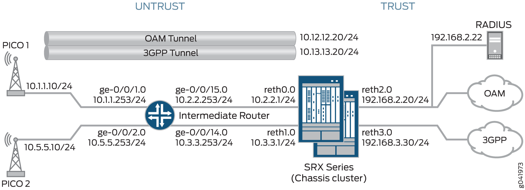
Each pico cell in this topology initiates two IPsec VPNs: one for management and one for data. In this example, management traffic uses the tunnel labeled OAM Tunnel, while the data traffic flows through the tunnel labeled 3GPP Tunnel. Each tunnel supports connections with OAM and 3GPP provisioning servers on separate, configurable networks, requiring separate routing instances and VPNs. This example provides the IKE Phase 1 and Phase 2 options for establishing the OAM and 3GPP VPNs.
In this example, the SRX Series acts as the IKEv2 configuration payload server, acquiring provisioning information from the RADIUS server and providing that information to the pico cell clients. The SRX Series returns the provisioning information for each authorized client in the IKEv2 configuration payload during tunnel negotiation. The SRX Series cannot be used as a client device.
Additionally, the SRX Series uses the IKEv2 configuration payload information to
update the Traffic Selector initiator (TSi) and Traffic Selector responder (TSr)
values exchanged with the client during tunnel negotiation. The configuration
payload uses the TSi and TSr values that are configured on the SRX Series using the
proxy-identity statement at the [edit security ipsec
vpn vpn-name ike] hierarchy level. The TSi and TSr
values define the network traffic for each VPN.
The intermediate router routes pico cell traffic to the appropriate interfaces on the SRX Series.
The following process describes the connection sequence:
-
The pico cell initiates an IPsec tunnel with the SRX Series using the factory configuration.
-
The SRX Series authenticates the client using the client certificate information and the root certificate of the CA that is enrolled in the SRX Series. After authentication, the SRX Series passes the IKE identity information from the client certificate to the RADIUS server in an authorization request.
-
After authorizing the client, the RADIUS server responds to the SRX Series with the client provisioning information:
-
IP address (TSi value)
-
IP subnet mask (optional; the default is 32 bit)
-
DNS address (optional)
-
-
The SRX Series returns the provisioning information in the IKEv2 configuration payload for each client connection, and exchanges final TSi and TSr values with the pico cells. In this example, the SRX Series provides the following TSi and TSr information for each VPN:
VPN Connection
TSi/TSr Values Provided by SRX
Pico 1 OAM
TSi: 10.12.1.201/32, TSr: 192.168.2.0/24
Pico 1 3GPP
TSi: 10.13.1.201/32, TSr: 192.168.3.0/24, TSr: 10.13.0.0/16
Pico 2 OAM
TSi: 10.12.1.205/32, TSr: 192.168.2.0/24
Pico 2 3GPP
TSi: 10.13.1.205/32, TSr: 192.168.3.0/24, TSr: 10.13.0.0/16
If the provisioning information supplied by the RADIUS server includes a subnet mask, the SRX Series returns a second TSr value for the client connection that includes the IP subnet. This enables intrapeer communication for devices on that subnet. In this example, intrapeer communication is enabled for the subnet associated with the 3GPP VPN (13.13.0.0/16).
The IKEv2 configuration payload feature is supported for both point-to-multipoint secure tunnel (st0) interfaces and point-to-point interfaces. For point-to-multipoint interfaces, the interfaces must be numbered, and the addresses provided in the configuration payload must be within the subnetwork range of the associated point-to-multipoint interface.
Starting in Junos OS Release 20.1R1, we support IKEv2 configuration payload feature with point-to-point interfaces on SRX5000 line and vSRX Virtual Firewall running iked.
Multinode High Availability supports IKEv2 configuration payload feature with point-to-point interfaces for secure tunnel (st0).
Table 7 shows the Phase 1 and Phase 2 options configured on the SRX Series, including information for establishing both OAM and 3GPP tunnels.
|
Option |
Value |
|---|---|
| IKE proposal: | |
|
Proposal name |
IKE_PROP |
|
Authentication method |
RSA digital certificates |
|
Diffie-Hellman (DH) group |
group5 |
|
Authentication algorithm |
SHA-1 |
|
Encryption algorithm |
AES 256 CBC |
| IKE policy: | |
|
IKE Policy name |
IKE_POL |
|
Local certificate |
Example_SRX |
| IKE gateway (OAM): | |
|
IKE policy |
IKE_POL |
|
Remote IP address |
dynamic |
|
IKE user type |
group-ike-id |
|
Local IKE ID |
hostname srx_series.example.net |
|
Remote IKE ID |
hostname .pico_cell.net |
|
External interface |
reth0.0 |
|
Access profile |
radius_pico |
|
IKE version |
v2-only |
| IKE gateway (3GPP): | |
|
IKE policy |
IKE_POL |
|
Remote IP address |
Dynamic |
|
IKE user type |
group-ike-id |
|
Local IKE ID |
distinguished-name wildcard OU=srx_series |
|
Remote IKE ID |
distinguished-name wildcard OU=pico_cell |
|
External interface |
reth1 |
|
Access profile |
radius_pico |
|
IKE version |
v2-only |
| IPsec proposal: | |
|
Proposal name |
IPSEC_PROP |
|
Protocol |
ESP |
|
Authentication algorithm |
HMAC SHA-1 96 |
|
Encryption algorithm |
AES 256 CBC |
| IPsec policy: | |
|
Policy name |
IPSEC_POL |
|
Perfect Forward Secrecy (PFS) keys |
group5 |
|
IPsec proposals |
IPSEC_PROP |
| IPsec VPN (OAM): | |
|
Bind interface |
st0.0 |
|
IKE gateway |
OAM_GW |
|
Local proxy-identity |
192.168.2.0/24 |
|
Remote proxy-identity |
0.0.0.0/0 |
|
IPsec policy |
IPSEC_POL |
| IPsec VPN (3GPP): | |
|
Bind interface |
st0.1 |
|
IKE gateway |
3GPP_GW |
|
Local proxy-identity |
192.168.3.0/24 |
|
Remote proxy-identity |
0.0.0.0/0 |
|
IPsec policy |
IPSEC_POL |
Certificates are stored on the pico cells and the SRX Series.
In this example, the default security policy that permits all traffic is used for all devices. More restrictive security policies should be configured for production environments. See Security Policies Overview.
Configuration
- Configuring the SRX Series
- Configuring the Intermediate Router
- Configuring the Pico Cell (Sample Configuration)
- Configuring the RADIUS Server (Sample Configuration using a FreeRADIUS)
Configuring the SRX Series
CLI Quick Configuration
To quickly configure this example, copy the following commands, paste them
into a text file, remove any line breaks, change any details necessary to
match your network configuration, copy and paste the commands into the CLI
at the [edit] hierarchy level, and then enter
commit from configuration mode.
set chassis cluster reth-count 5
set chassis cluster node 0
set chassis cluster node 1
set chassis cluster redundancy-group 0 node 0 priority 250
set chassis cluster redundancy-group 0 node 1 priority 150
set chassis cluster redundancy-group 1 node 0 priority 220
set chassis cluster redundancy-group 1 node 1 priority 149
set chassis cluster redundancy-group 1 interface-monitor ge-3/0/0 weight 255
set chassis cluster redundancy-group 1 interface-monitor ge-8/0/0 weight 255
set chassis cluster redundancy-group 1 interface-monitor ge-3/0/1 weight 255
set chassis cluster redundancy-group 1 interface-monitor ge-8/0/1 weight 255
set chassis cluster redundancy-group 1 interface-monitor ge-3/2/0 weight 255
set chassis cluster redundancy-group 1 interface-monitor ge-8/2/0 weight 255
set chassis cluster redundancy-group 1 interface-monitor ge-3/2/1 weight 255
set chassis cluster redundancy-group 1 interface-monitor ge-8/2/1 weight 255
set interfaces ge-3/0/0 gigether-options redundant-parent reth0
set interfaces ge-3/0/1 gigether-options redundant-parent reth1
set interfaces ge-3/2/0 gigether-options redundant-parent reth2
set interfaces ge-3/2/1 gigether-options redundant-parent reth3
set interfaces ge-8/0/0 gigether-options redundant-parent reth0
set interfaces ge-8/0/1 gigether-options redundant-parent reth1
set interfaces ge-8/2/0 gigether-options redundant-parent reth2
set interfaces ge-8/2/1 gigether-options redundant-parent reth3
set interfaces reth0 redundant-ether-options redundancy-group 1
set interfaces reth0 unit 0 family inet address 10.2.2.1/24
set interfaces reth1 redundant-ether-options redundancy-group 1
set interfaces reth1 unit 0 family inet address 10.3.3.1/24
set interfaces reth2 redundant-ether-options redundancy-group 1
set interfaces reth2 unit 0 family inet address 192.168.2.20/24
set interfaces reth3 redundant-ether-options redundancy-group 1
set interfaces reth3 unit 0 family inet address 192.168.3.20/24
set interfaces st0 unit 0 multipoint
set interfaces st0 unit 0 family inet address 10.12.1.20/24
set interfaces st0 unit 1 multipoint
set interfaces st0 unit 1 family inet address 10.13.1.20/24
set routing-options static route 10.1.0.0/16 next-hop 10.2.2.253
set routing-options static route 10.5.0.0/16 next-hop 10.2.2.253
set security zones security-zone untrust host-inbound-traffic system-services all
set security zones security-zone untrust host-inbound-traffic protocols all
set security zones security-zone untrust interfaces reth0.0
set security zones security-zone untrust interfaces reth1.0
set security zones security-zone oam-trust host-inbound-traffic system-services all
set security zones security-zone oam-trust host-inbound-traffic protocols all
set security zones security-zone oam-trust interfaces reth2.0
set security zones security-zone oam-trust interfaces st0.0
set security zones security-zone 3gpp-trust host-inbound-traffic system-services all
set security zones security-zone 3gpp-trust host-inbound-traffic protocols all
set security zones security-zone 3gpp-trust interfaces reth3.0
set security zones security-zone 3gpp-trust interfaces st0.1
set access profile radius_pico authentication-order radius
set access profile radius_pico radius-server 192.168.2.22 secret "$ABC123"
set access profile radius_pico radius-server 192.168.2.22 routing-instance VR-OAM
set security ike proposal IKE_PROP authentication-method rsa-signatures
set security ike proposal IKE_PROP dh-group group5
set security ike proposal IKE_PROP authentication-algorithm sha1
set security ike proposal IKE_PROP encryption-algorithm aes-256-cbc
set security ike policy IKE_POL proposals IKE_PROP
set security ike policy IKE_POL certificate local-certificate example_SRX
set security ike gateway OAM_GW ike-policy IKE_POL
set security ike gateway OAM_GW dynamic hostname .pico_cell.net
set security ike gateway OAM_GW dynamic ike-user-type group-ike-id
set security ike gateway OAM_GW local-identity hostname srx_series.example.net
set security ike gateway OAM_GW external-interface reth0.0
set security ike gateway OAM_GW aaa access-profile radius_pico
set security ike gateway OAM_GW version v2-only
set security ike gateway 3GPP_GW ike-policy IKE_POL
set security ike gateway 3GPP_GW dynamic distinguished-name wildcard OU=pico_cell
set security ike gateway 3GPP_GW dynamic ike-user-type group-ike-id
set security ike gateway 3GPP_GW local-identity distinguished-name wildcard OU=srx_series
set security ike gateway 3GPP_GW external-interface reth1.0
set security ike gateway 3GPP_GW aaa access-profile radius_pico
set security ike gateway 3GPP_GW version v2-only
set security ipsec proposal IPSEC_PROP protocol esp
set security ipsec proposal IPSEC_PROP authentication-algorithm hmac-sha1-96
set security ipsec proposal IPSEC_PROP encryption-algorithm aes-256-cbc
set security ipsec proposal IPSEC_PROP lifetime-seconds 300
set security ipsec policy IPSEC_POL perfect-forward-secrecy keys group5
set security ipsec policy IPSEC_POL proposals IPSEC_PROP
set security ipsec vpn OAM_VPN bind-interface st0.0
set security ipsec vpn OAM_VPN ike gateway OAM_GW
set security ipsec vpn OAM_VPN ike proxy-identity local 192.168.2.0/24
set security ipsec vpn OAM_VPN ike proxy-identity remote 0.0.0.0/0
set security ipsec vpn OAM_VPN ike ipsec-policy IPSEC_POL
set security ipsec vpn 3GPP_VPN bind-interface st0.1
set security ipsec vpn 3GPP_VPN ike gateway 3GPP_GW
set security ipsec vpn 3GPP_VPN ike proxy-identity local 192.168.3.0/24
set security ipsec vpn 3GPP_VPN ike proxy-identity remote 0.0.0.0/0
set security ipsec vpn 3GPP_VPN ike ipsec-policy IPSEC_POL
set routing-instances VR-OAM instance-type virtual-router
set routing-instances VR-OAM interface reth2.0
set routing-instances VR-OAM interface st0.0
set routing-instances VR-3GPP instance-type virtual-router
set routing-instances VR-3GPP interface reth3.0
set routing-instances VR-3GPP interface st0.1
set security policies default-policy permit-all
Step-by-Step Procedure
The following example requires you to navigate various levels in the configuration hierarchy. For instructions on how to do that, see Using the CLI Editor in Configuration Mode.
To configure the SRX Series:
-
Configure the chassis cluster.
[edit chassis cluster]
user@host# set reth-count 5
user@host# set node 0
user@host# set node 1
user@host#set redundancy-group 0 node 0 priority 250
user@host#set redundancy-group 0 node 1 priority 150
user@host#set redundancy-group 1 node 0 priority 220
user@host#set redundancy-group 1 node 1 priority 149
user@host# set redundancy-group 1 interface-monitor ge-3/0/0 weight 255
user@host# set redundancy-group 1 interface-monitor ge-8/0/0 weight 255
user@host# set redundancy-group 1 interface-monitor ge-3/0/1 weight 255
user@host# set redundancy-group 1 interface-monitor ge-8/0/1 weight 255
user@host# set redundancy-group 1 interface-monitor ge-3/2/0 weight 255
user@host# set redundancy-group 1 interface-monitor ge-8/2/0 weight 255
user@host# set redundancy-group 1 interface-monitor ge-3/2/1 weight 255
user@host# set redundancy-group 1 interface-monitor ge-8/2/1 weight 255
-
Configure interfaces.
[edit interfaces]
user@host# set ge-3/0/0 gigether-options redundant-parent reth0
user@host# set ge-3/0/1 gigether-options redundant-parent reth1
user@host# set ge-3/2/0 gigether-options redundant-parent reth2
user@host# set ge-3/2/1 gigether-options redundant-parent reth3
user@host# set ge-8/0/0 gigether-options redundant-parent reth0
user@host# set ge-8/0/1 gigether-options redundant-parent reth1
user@host# set ge-8/2/0 gigether-options redundant-parent reth2
user@host# set ge-8/2/1 gigether-options redundant-parent reth3
user@host# set reth0 redundant-ether-options redundancy-group 1
user@host# set reth0 unit 0 family inet address 10.2.2.1/24
user@host# set reth1 redundant-ether-options redundancy-group 1
user@host# set reth1 unit 0 family inet address 10.3.3.1/24
user@host# set reth2 redundant-ether-options redundancy-group 1
user@host# set reth2 unit 0 family inet address 192.168.2.20/24
user@host# set reth3 redundant-ether-options redundancy-group 1
user@host# set reth3 unit 0 family inet address 192.169.3.20/24
user@host# set st0 unit 0 multipoint
user@host# set st0 unit 0 family inet address 10.12.1.20/24
user@host# set st0 unit 1 multipoint
user@host# set st0 unit 1 family inet address 10.13.1.20/24
-
Configure routing options.
[edit routing-options]
user@host# set static route 10.1.0.0/16 next-hop 10.2.2.253
user@host# set static route 10.5.0.0/16 next-hop 10.2.2.253
-
Specify security zones.
[edit security zones security-zone untrust]
user@host# set host-inbound-traffic protocols all
user@host# set host-inbound-traffic system-services all
user@host# set interfaces reth0.0
user@host# set interfaces reth1.0
[edit security zones security-zone oam-trust]
user@host# set host-inbound-traffic system-services all
user@host# set host-inbound-traffic protocols all
user@host# set interfaces reth2.0
user@host# set interfaces st0.0
[edit security zones security-zone 3gpp-trust]
user@host# set host-inbound-traffic system-services all
user@host# set host-inbound-traffic protocols all
user@host# set interfaces reth3.0
user@host# set interfaces st0.1
-
Create the RADIUS profile.
[edit access profile radius_pico]
user@host# set authentication-order radius
user@host# set radius-server 192.168.2.22 secret “$ABC123”
user@host# set radius-server 192.168.2.22 routing-instance VR-OAM
-
Configure Phase 1 options.
[edit security ike proposal IKE_PROP]
user@host# set authentication-method rsa-signatures
user@host# set dh-group group5
user@host# set authentication-algorithm sha1
user@host# set encryption-algorithm aes-256-cbc
[edit security ike policy IKE_POL]
user@host# set proposals IKE_PROP
user@host# set certificate local-certificate example_SRX
[edit security ike gateway OAM_GW]
user@host# set ike-policy IKE_POL
user@host# set dynamic hostname .pico_cell.net
user@host# set dynamic ike-user-type group-ike-id
user@host# set local-identity hostname srx.example.net
user@host# set external-interface reth0.0
user@host# set aaa access-profile radius_pico
user@host# set version v2-only
[edit security ike gateway 3GPP_GW]
user@host# set ike-policy IKE_POL
user@host# set dynamic distinguished-name wildcard OU=pico_cell
user@host# set dynamic ike-user-type group-ike-id
user@host# set local-identity distinguished-name wildcard OU=srx_series
user@host# set external-interface reth1.0
user@host# set aaa access-profile radius_pico
user@host# set version v2-only
-
Specify Phase 2 options.
[edit set security ipsec proposal IPSEC_PROP]
user@host# set protocol esp
user@host# set authentication-algorithm hmac-sha1-96
user@host# set encryption-algorithm aes-256-cbc
user@host# set lifetime-seconds 300
[edit security ipsec policy IPSEC_POL]
user@host# set perfect-forward-secrecy keys group5
user@host# set proposals IPSEC_PROP
[edit security ipsec vpn OAM_VPN]
user@host# set bind-interface st0.0
user@host# set ike gateway OAM_GW
user@host# set ike proxy-identity local 192.168.2.0/24
user@host# set ike proxy-identity remote 0.0.0.0/0
user@host# set ike ipsec-policy IPSEC_POL
[edit security ipsec vpn 3GPP_VPN]
user@host# set bind-interface st0.1
user@host# set ike gateway 3GPP_GW
user@host# set ike proxy-identity local 192.168.3.0/24
user@host# set ike proxy-identity remote 0.0.0.0/0
user@host# set ike ipsec-policy IPSEC_POL
-
Specify the routing instances.
[edit routing-instances VR-OAM]
user@host# set instance-type virtual router
user@host# set interface reth2.0
user@host# set interface st0.0
[edit routing-instances VR-3GPP]
user@host# set instance-type virtual router
user@host# set interface reth3.0
user@host# set interface st0.1
-
Specify security policies to permit site-to-site traffic.
[edit security policies]
user@host# set default-policy permit-all
Results
From configuration mode, confirm your configuration by entering the
show chassis cluster, show interfaces,
show security zones, show access profile
radius_pico, show security ike, show
security ipsec, show routing-instances, and
show security policies commands. If the output does not
display the intended configuration, repeat the configuration instructions in
this example to correct it.
[edit]
user@host# show chassis cluster
reth-count 5
node 0
node 1
redundancy-group 0{
    node 0 priority 250;
    node 1 priority 150;
    redundancy-group 1 {
    node 0 priority 220;
    node 1 priority 149;
    interface-monitor {
        ge-3/0/0 weight 255;
        ge-8/0/0 weight 255;
        ge-3/0/1 weight 255;
        ge-8/0/1 weight 255;
        ge-3/2/0 weight 255;
        ge-8/2/0 weight 255;
        ge-3/2/1 weight 255;
        ge-8/2/1 weight 255;
    }
}
[edit]
user@host# show interfaces
ge-3/0/0 {
    gigether-options {
        redundant-parent reth0;
    }
}
ge-3/0/1 {
    gigether-options {
        redundant-parent reth1;
    }
}
ge-3/2/0 {
    gigether-options {
        redundant-parent reth2;
    }
}
ge-3/2/1 {
    gigether-options {
        redundant-parent reth3;
    }
}
ge-8/0/0 {
    gigether-options {
        redundant-parent reth0;
    }
}
ge-8/0/1 {
    gigether-options {
        redundant-parent reth1;
    }
}
ge-8/2/0 {
    gigether-options {
        redundant-parent reth2;
    }
}
ge-8/2/1 {
    gigether-options {
        redundant-parent reth3;
    }
}
reth0 {
    redundant-ether-options {
        redundancy-group 1;
    }
    unit 0 {
        family inet {
            address 10.2.2.1/24;
        }
    }
}
reth1 {
    redundant-ether-options {
        redundancy-group 1;
    }
    unit 0 {
        family inet {
            address 10.3.3.1/24;
        }
    }
}
reth2 {
    redundant-ether-options {
        redundancy-group 1;
    }
    unit 0 {
        family inet {
            address 192.168.2.20/24;
        }
    }
}
reth3 {
    redundant-ether-options {
        redundancy-group 1;
    }
    unit 0 {
        family inet {
            address 192.168.3.20/24;
        }
    }
}
st0 {
    unit 0{
        multipoint;
        family inet {
            address 12.12.1.20/24;
        }
    }
    unit 1{
        multipoint;
        family inet {
            address 13.13.1.20/24;
        }
    }
}
[edit]
user@host# show routing-options
static {
    route 10.1.0.0/16 next-hop 10.2.2.253;
    route 10.5.0.0/16 next-hop 10.2.2.253;
}
[edit]
user@host# show security zones
security-zone untrust {
    host-inbound-traffic {
        system-services {
            all;
        }
        protocols {
            all;
        }
    }
    interfaces {
        reth1.0;
        reth0.0;
    }
}
security-zone oam-trust {
    host-inbound-traffic {
        system-services {
            all;
        }
        protocols {
            all;
        }
    }
    interfaces {
        reth2.0;
        st0.0;
    }
}
security-zone 3gpp-trust {
    host-inbound-traffic {
        system-services {
            all;
        }
        protocols {
            all;
        }
    }
    interfaces {
        reth3.0;
        st0.1;
    }
}
[edit]
user@host# show access profile radius_pico
authentication-order radius;
radius-server {
    192.168.2.22 {
        secret "$ABC123";
        routing-instance VR-OAM;
    }
}
[edit]
user@host# show security ike
proposal IKE_PROP {
    authentication-method rsa-signatures;
    dh-group group5;
    authentication-algorithm sha1;
    encryption-algorithm aes-256-cbc;
}
policy IKE_POL {
    proposals IKE_PROP;
    certificate {
        local-certificate example_SRX;
    }
}
gateway OAM_GW {
    ike-policy IKE_POL;
    dynamic {
        hostname .pico_cell.net;
        ike-user-type group-ike-id;
    }
    local-identity hostname srx_series.example.net;
    external-interface reth0.0;
    aaa access-profile radius_pico;
    version v2-only;
}
gateway 3GPP_GW {
    ike-policy IKE_POL;
    dynamic {
        distinguished-name {
            wildcard OU=pico_cell;
        }
        ike-user-type group-ike-id;
    }
    local-identity distinguished-name;
    external-interface reth1.0;
    aaa access-profile radius_pico;
    version v2-only;
}
[edit]
user@host# show security ipsec
proposal IPSEC_PROP {
    protocol esp;
    authentication-algorithm hmac-sha1-96;
    encryption-algorithm aes-256-cbc;
    lifetime-seconds 300;
}
policy IPSEC_POL {
    perfect-forward-secrecy {
        keys group5;
    }
    proposals IPSEC_PROP;
}
vpn OAM_VPN {
    bind-interface st0.0;
    ike {
        gateway OAM_GW;
        proxy-identity {
            local 192.168.2.0/24;
            remote 0.0.0.0/0;
        }
        ipsec-policy IPSEC_POL;
    }
}
vpn 3GPP_VPN {
    bind-interface st0.1;
    ike {
        gateway 3GPP_GW;
        proxy-identity {
            local 192.168.3.0/24;
            remote 0.0.0.0/0;
        }
        ipsec-policy IPSEC_POL;
    }
}
[edit]
user@host# show routing-instances
VR-OAM {
    instance-type virtual-router;
    interface reth2.0;
    interface st0.0;
}
VR-3GPP {
    instance-type virtual-router;
    interface reth3.0;
    interface st0.1;
}
[edit]
user@host# show security policies
default-policy {
    permit-all;
}
If you are done configuring the device, enter commit from
configuration mode.
Configuring the Intermediate Router
CLI Quick Configuration
To quickly configure this example, copy the following commands, paste them
into a text file, remove any line breaks, change any details necessary to
match your network configuration, copy and paste the commands into the CLI
at the [edit] hierarchy level, and then enter
commit from configuration mode.
set interfaces ge-0/0/1 unit 0 family inet address 10.1.1.253/24
set interfaces ge-0/0/2 unit 0 family inet address 10.5.5.253/24
set interfaces ge-0/0/14 unit 0 family inet address 10.3.3.253/24
set interfaces ge-0/0/15 unit 0 family inet address 10.2.2.253/24
set routing-options static route 192.168.3.0/24 next-hop 10.2.2.1
set security zones security-zone trust host-inbound-traffic system-services all
set security zones security-zone trust host-inbound-traffic protocols all
set security zones security-zone trust interfaces ge-0/0/14.0
set security zones security-zone trust interfaces ge-0/0/15.0
set security zones security-zone untrust host-inbound-traffic system-services all
set security zones security-zone untrust host-inbound-traffic protocols all
set security zones security-zone untrust interfaces ge-0/0/1.0
set security zones security-zone untrust interfaces ge-0/0/2.0
set security policies default-policy permit-all
Step-by-Step Procedure
The following example requires you to navigate various levels in the configuration hierarchy. For instructions on how to do that, see Using the CLI Editor in Configuration Mode.
To configure the intermediate router:
-
Configure interfaces.
[edit interfaces]
user@host# set ge-0/0/1 unit 0 family inet address 10.1.1.253/24
user@host# set ge-0/0/2 unit 0 family inet address 10.5.5.253/24
user@host# set ge-0/0/14 unit 0 family inet address 10.3.3.253/24
user@host# set ge-0/0/15 unit 0 family inet address 10.2.2.253/24
-
Configure routing options.
[edit routing-options]
user@host# set static route 192.168.3.0/24  next-hop 10.2.2.1
-
Specify security zones.
[edit security zones security-zone trust]
user@host# set host-inbound-traffic protocols all
user@host# set host-inbound-traffic system-services all
user@host# set interfaces ge-0/0/14.0
user@host# set interfaces ge-0/0/15.0
[edit security zones security-zone untrust]
user@host# set host-inbound-traffic system-services all
user@host# set host-inbound-traffic protocols all
user@host# set interfaces ge-0/0/1.0
user@host# set interfaces ge-0/0/2.0
-
Specify security policies.
[edit security policies]
user@host# set default-policy permit-all
Results
From configuration mode, confirm your configuration by entering the
show interfaces, show routing-options,
show security zones, and show security
policies commands. If the output does not display the intended
configuration, repeat the configuration instructions in this example to
correct it.
[edit]
user@host# show interfaces
ge-0/0/1 {
    unit 0 {
        family inet {
            address 10.1.1.253/24;
        }
    }
}
ge-0/0/2 {
    unit 0 {
        family inet {
            address 10.5.5.253/24;
        }
    }
}
ge-0/0/14 {
    unit 0 {
        family inet {
            address 10.3.3.253/24;
        }
    }
}
ge-0/0/15 {
    unit 0 {
        family inet {
            address 10.2.2.253/24;
        }
    }
}
[edit]
user@host# show routing-options
static {
    route 192.168.3.0/24 next-hop 10.2.2.1;
}
[edit]
user@host# show security zones
security-zone trust {
    host-inbound-traffic {
        system-services {
            all;
        }
        protocols {
            all;
        }
    }
    interfaces {
        ge-0/0/14.0;
        ge-0/0/15.0;
    }
}
security-zone untrust {
    host-inbound-traffic {
        system-services {
            all;
        }
        protocols {
            all;
        }
    }
    interfaces {
        ge-0/0/1.0;
        ge-0/0/2.0;
    }
}
}
[edit]
user@host# show security policies
default-policy {
    permit-all;
}
If you are done configuring the device, enter commit from
configuration mode.
Configuring the Pico Cell (Sample Configuration)
Step-by-Step Procedure
The pico cell information in this example is provided for reference. Detailed pico cell configuration information is beyond the scope of this document. The pico cell factory configuration must include the following information:
-
Local certificate (X.509v3) and IKE identity information
-
Traffic Selector (TSi, TSr) values set to any/any (0.0.0.0/0)
-
SRX Series IKE identity information and public IP address
-
Phase 1 and Phase 2 proposals that match the SRX Series configuration
The pico cells in this example use strongSwan open source software for IPsec-based VPN connections. This information is used by the SRX Series for pico cell provisioning using the IKEv2 configuration payload feature. In networks where many devices are being deployed, the pico cell configuration can be identical except for the certificate (leftcert) and identity (leftid) information. The following sample configurations illustrate factory settings.
-
Review the Pico 1 configuration:
Pico 1: Sample Configuration
conn %default ikelifetime=8h keylife=1h rekeymargin=1m keyingtries=1 keyexchange=ikev2 authby=pubkey mobike=no conn oam left=%any leftsourceip=%config leftcert=/usr/local/etc/ipsec.d/certs/<cert_name> leftid=pico1.pico_cell.net leftfirewall=yes reauth=yes right=10.2.2.1/24 rightid=srx_series.example.net rightsubnet=0.0.0.0/0 #peer net for proxy id ike=aes256-sha-modp1536! esp=aes256-sha-modp1536! auto=add conn 3gpp left=%any leftsourceip=%config leftcert=/usr/local/etc/ipsec.d/certs/<cert_name> leftid=”C=US, ST=CA, L=Sunnyvale, O=org, OU=pico_cell, CN=pico1” leftfirewall=yes reauth=yes right=10.3.3.1/24 rightid=”OU=srx_series” rightsubnet=0.0.0.0/0 #peer net for proxy id ike=aes256-sha-modp1536! esp=aes256-sha-modp1536! auto=add -
Review the Pico 2 configuration:
Pico 2 Sample Configuration
conn %default
        ikelifetime=8h
        keylife=1h
        rekeymargin=1m
        keyingtries=1
        keyexchange=ikev2
        authby=pubkey
        mobike=no

conn oam
        left=%any
        leftsourceip=%config
        leftcert=/usr/local/etc/ipsec.d/certs/<cert_name>
        leftid=pico2.pico_cell.net
        leftfirewall=yes
        #reauth=no
        right=10.2.2.1/24
        rightid=srx_series.example.net
        rightsubnet=0.0.0.0/0 #peer net for proxy id
        ike=aes256-sha-modp1536!
        esp=aes256-sha-modp1536!
        auto=add

conn 3gpp
        left=%any
        leftsourceip=%config
        leftcert=/usr/local/etc/ipsec.d/certs/<cert_name>
        leftid=”C=US, ST=CA, L=Sunnyvale, O=org, OU=pico_cell, CN=pico2”
        leftfirewall=yes
        #reauth=no
        right=10.3.3.1/24
        rightid=”OU=srx_series”
        rightsubnet=0.0.0.0/0 #peer net for proxy id
        ike=aes256-sha-modp1536!
        esp=aes256-sha-modp1536!
        auto=add
Configuring the RADIUS Server (Sample Configuration using a FreeRADIUS)
Step-by-Step Procedure
The RADIUS server information in this example is provided for reference. Complete RADIUS server configuration information is beyond the scope of this document. The following information is returned to the SRX Series by the RADIUS server:
-
Framed-IP-Address
-
Framed-IP-Netmask (optional)
-
Primary-DNS and Secondary-DNS (optional)
In this example, the RADIUS server has separate provisioning information for the OAM and 3GPP connections. The User-Name is taken from the client certificate information provided in the SRX Series authorization request.
If the RADIUS server acquires client provisioning information from a DHCP server, the client identity information relayed to the DHCP server by the RADIUS server must be consistent with the client IKE identity information relayed to the RADIUS server by the SRX Series Firewall. This ensures the continuity of the client identity across the various protocols.
The communication channel between the SRX Series Firewall and the RADIUS server is protected by a RADIUS shared secret.
-
Review the RADIUS configuration for the Pico 1 OAM VPN. The RADIUS server has the following information:
Sample RADIUS configuration in Junos OS Releases 12.3X48 and Junos OS releases prior to 15.1X49-D160, 17.3R3, 17.4R2, 18.1R3, 18.2R2, 18.3R1, and 18.1R3-S2:
FreeRADIUS configuration example:
DEFAULT User-Name =~ "device@example.net", Cleartext-Password := "juniper"
        Service-Type = Framed-User,
        Framed-IP-Address = 10.12.1.201,
        Framed-IP-Netmask = 255.255.255.255,
        Primary-Dns = 192.168.2.104,
        Secondary-Dns = 192.168.2.106,
Sample RADIUS configuration starting from Junos OS Releases 15.X49-D161, 15.1X49-D170, 17.3R3, 17.4R2, 18.1R3, 18.2R2, 18.3R1, and 18.1R3-S2:
FreeRADIUS configuration example:
DEFAULT User-Name =~ "device@example.net", Auth-Type := "Accept"
        Service-Type = Framed-User,
        Framed-IP-Address = 10.12.1.201,
        Framed-IP-Netmask = 255.255.255.255,
        Primary-Dns = 192.168.2.104,
        Secondary-Dns = 192.168.2.106,
In this case, the RADIUS server provides the default subnet mask (255.255.255.255), which blocks intrapeer traffic.
-
Review the RADIUS configuration for the Pico 1 3GPP VPN. The RADIUS server has the following information:
Sample RADIUS configuration in Junos OS Releases 12.3X48 and Junos OS releases prior to 15.1X49-D160, 17.3R3, 17.4R2, 18.1R3, 18.2R2, 18.3R1, and 18.1R3-S2:
FreeRADIUS configuration example:
DEFAULT User-Name =~ "device@example.net", Cleartext-Password := "juniper"
       Service-Type = Framed-User,
        Framed-IP-Address = 10.13.1.201.10,
        Framed-IP-Netmask = 255.255.0.0,
        Primary-Dns = 192.168.2.104,
        Secondary-Dns = 192.168.2.106,
Sample RADIUS configuration starting from Junos OS Releases 15.X49-D161, 15.1X49-D170, 17.3R3, 17.4R2, 18.1R3, 18.2R2, 18.3R1, and 18.1R3-S2:
FreeRADIUS configuration example:
DEFAULT User-Name =~ "device@example.net", Auth-Type := "Accept"
       Service-Type = Framed-User,
        Framed-IP-Address = 10.13.1.201.10,
        Framed-IP-Netmask = 255.255.0.0,
        Primary-Dns = 192.168.2.104,
        Secondary-Dns = 192.168.2.106,
In this case, the RADIUS server provides a subnet mask value (255.255.0.0), which enables intrapeer traffic.
Starting in Junos OS Release 20.1R1, you can configure a common password for IKEv2 configuration payload requests for an IKE gateway configuration. The common password in the range of 1 to 128 characters allows the administrator to define a common password. This password is used between the SRX Series Firewall and the RADIUS server when the SRX Series Firewall requesting an IP address on behalf of a remote IPsec peer using IKEv2 configuration payload. RADIUS server validate the credentials before it provides any IP information to the SRX Series Firewall for the configuration payload request. You can configure the common password using
config-payload-password
                                        configured-password
configuration statement at[edit security ike gateway gateway-name aaa access-profile access-profile-name]hierarchy level. Additionally, this example creates two tunnels from the same client certificate by using different parts of the certificate for User-Name (IKE identity) information.
Verification
Confirm that the configuration is working properly.
- Verifying the IKE Phase 1 Status for the SRX Series
- Verifying IPsec Security Associations for the SRX Series
Verifying the IKE Phase 1 Status for the SRX Series
Purpose
Verify the IKE Phase 1 status.
Action
From operational mode on node 0, enter the show security ike security-associations command. After obtaining an index number from the command, use the show security ike security-associations detail command.
user@host# show security ike security-associations
node0:
--------------------------------------------------------------------------
Index      State  Initiator cookie  Responder cookie  Mode  Remote Address
553329718  UP     99919a471d1a5278  3be7c5a49172e6c2  IKEv2 10.1.1.1
1643848758 UP     9e31d4323195a195  4d142438106d4273  IKEv2 10.1.1.1
user@host# show security ike security-associations index 553329718 detail
node0:
--------------------------------------------------------------------------
IKE peer 10.1.1.1, Index 553329718, Gateway Name: OAM_GW
  Location: FPC 2, PIC 0, KMD-Instance 1
  Role: Responder, State: UP
  Initiator cookie: 99919a471d1a5278, Responder cookie: 3be7c5a49172e6c2
  Exchange type: IKEv2, Authentication method: RSA-signatures
  Local: 10.2.2.1:500, Remote: 10.1.1.1:500
  Lifetime: Expires in 28738 seconds
  Peer ike-id: C=US, ST=CA, L=Sunnyvale, O=org, OU=pico_cell, CN=pico1
  aaa assigned IP: 10.12.1.201
  Algorithms:
   Authentication        : hmac-sha1-96
   Encryption            : aes256-cbc
   Pseudo random function: hmac-sha1
   Diffie-Hellman group  : DH-group-5
  Traffic statistics:
   Input  bytes  :                 2104
   Output bytes  :                  425
  Input  packets:                    2
   Output packets:                    1
  IPSec security associations: 0 created, 0 deleted
  Phase 2 negotiations in progress: 1
Meaning
The show security ike security-associations command lists
all active IKE Phase 1 SAs with pico cells devices. If no SAs are listed,
there was a problem with Phase 1 establishment. Check the IKE policy
parameters and external interface settings in your configuration. This
example shows only the IKE Phase 1 SA for the OAM VPN; however, a separate
IKE Phase 1 SA will be displayed showing the IKE Phase 1 parameters for the
3GPP VPN.
If SAs are listed, review the following information:
-
Index—This value is unique for each IKE SA: you can use the
show security ike security-associations index
                                    detail
command to get more information about the SA. -
Remote address—Verify that the local IP address is correct and that port 500 is being used for peer-to-peer communication.
-
Role responder state:
-
Up—The Phase 1 SA has been established.
-
Down—There was a problem establishing the Phase 1 SA.
-
-
Peer (remote) IKE ID—Verify the certificate information is correct.
-
Local identity and remote identity—Verify these addresses are correct.
-
Mode—Verify that the correct mode is being used.
Verify that the following items are correct in your configuration:
-
External interfaces (the interface must be the one that sends IKE packets)
-
IKE policy parameters
-
Phase 1 proposal parameters (must match between peers)
The show security ike security-associations command lists
the following additional information about security associations:
-
Authentication and encryption algorithms used
-
Phase 1 lifetime
-
Traffic statistics (can be used to verify that traffic is flowing properly in both directions)
-
Role information
Troubleshooting is best performed on the peer using the responder role.
-
Initiator and responder information
-
Number of IPsec SAs created
-
Number of Phase 2 negotiations in progress
Verifying IPsec Security Associations for the SRX Series
Purpose
Verify the IPsec status.
Action
From operational mode on node 0, enter the show security ipsec security-associations command. After obtaining an index number from the command, use the show security ipsec security-associations detail command.
user@host# show security ipsec security-associations
node0:
--------------------------------------------------------------------------
  Total active tunnels: 2
  ID         Algorithm             SPI     Life:sec/kb Mon lsys Port Gateway
  <214171651 ESP:aes-cbc-256/sha1 cc2869e2 3529/        -  root 500  10.1.1.1
  >214171651 ESP:aes-cbc-256/sha1 c0a54936 3529/        -  root 500  10.1.1.1
  <205520899 ESP:aes-cbc-256/sha1 84e49026 3521/        -  root 500  10.1.1.1
  >205520899 ESP:aes-cbc-256/sha1 c4ed1849 3521/        -  root 500  10.1.1.1
user@host# show security ipsec security-associations detail
node0:
--------------------------------------------------------------------------
Port: 500, Nego#: 0, Fail#: 0, Def-Del#: 0 Flag: 0x604a29
Last Tunnel Down Reason: SA not initiated
  ID: 214171651 Virtual-system: root, VPN Name: 3GPP_VPN
  Local Gateway: 10.3.3.1, Remote Gateway: 10.1.1.1
  Local Identity: list(any:0,ipv4_subnet(any:0-65535,[0..7]=192.168.3.0/24), ipv4_subnet(any:0-65535,[0..7]=10.13.0.0/16))
  Remote Identity: ipv4(any:0,[0..3]=10.13.1.201)
    DF-bit: clear
    Bind-interface: st0.1

  Port: 500, Nego#: 0, Fail#: 0, Def-Del#: 0 Flag: 0x608a29
  Last Tunnel Down Reason: SA not initiated
    Location: FPC 6, PIC 0, KMD-Instance 2
    Direction: inbound, SPI: cc2869e2, AUX-SPI: 0
                              , VPN Monitoring: -
    Hard lifetime: Expires in 3523 seconds
    Lifesize Remaining:
    Soft lifetime: Expires in 2965 seconds
    Mode: Tunnel(0 0), Type: dynamic, State: installed
    Protocol: ESP, Authentication: hmac-sha1-96, Encryption: aes-cbc (256 bits)
    Anti-replay service: counter-based enabled, Replay window size: 64

    Location: FPC 6, PIC 0, KMD-Instance 2
    Direction: outbound, SPI: c0a54936, AUX-SPI: 0
                              , VPN Monitoring: -
    Hard lifetime: Expires in 3523 seconds
    Lifesize Remaining:
    Soft lifetime: Expires in 2965 seconds
    Mode: Tunnel(0 0), Type: dynamic, State: installed
    Protocol: ESP, Authentication: hmac-sha1-96, Encryption: aes-cbc (256 bits)
    Anti-replay service: counter-based enabled, Replay window size: 64

  ID: 205520899 Virtual-system: root, VPN Name: OAM_VPN
  Local Gateway: 10.2.2.1, Remote Gateway: 10.1.1.1
  Local Identity: ipv4_subnet(any:0-65535,[0..7]=192.168.2.0/24)
  Remote Identity: ipv4(any:0,[0..3]=10.12.1.201)
  Version: IKEv2
    DF-bit: clear
    Bind-interface: st0.0

  Port: 500, Nego#: 0, Fail#: 0, Def-Del#: 0 Flag: 0x608a29
  Last Tunnel Down Reason: SA not initiated
    Location: FPC 2, PIC 0, KMD-Instance 1
    Direction: inbound, SPI: 84e49026, AUX-SPI: 0
                              , VPN Monitoring: -
    Hard lifetime: Expires in 3515 seconds
    Lifesize Remaining:
    Soft lifetime: Expires in 2933 seconds
    Mode: Tunnel(0 0), Type: dynamic, State: installed
    Protocol: ESP, Authentication: hmac-sha1-96, Encryption: aes-cbc (256 bits)
    Anti-replay service: counter-based enabled, Replay window size: 64

    Location: FPC 2, PIC 0, KMD-Instance 1
    Direction: outbound, SPI: c4ed1849, AUX-SPI: 0
                              , VPN Monitoring: -
    Hard lifetime: Expires in 3515 seconds
    Lifesize Remaining:
    Soft lifetime: Expires in 2933 seconds
    Mode: Tunnel(0 0), Type: dynamic, State: installed
    Protocol: ESP, Authentication: hmac-sha1-96, Encryption: aes-cbc (256 bits)
    Anti-replay service: counter-based enabled, Replay window size: 64
Meaning
This examples shows the active IKE Phase 2 SAs for Pico 1. If no SAs are
listed, there was a problem with Phase 2 establishment. Check the IPsec
policy parameters in your configuration. For each Phase 2 SA (OAM and 3GPP),
information is provided in both the inbound and outboard direction. The
output from the show security ipsec security-associations
command lists the following information:
-
The remote gateway has an IP address of 10.1.1.1.
-
The SPIs, lifetime (in seconds), and usage limits (or lifesize in KB) are shown for both directions. The 3529/ value indicates that the Phase 2 lifetime expires in 3529 seconds, and that no lifesize has been specified, which indicates that it is unlimited. The Phase 2 lifetime can differ from the Phase 1 lifetime, because Phase 2 is not dependent on Phase 1 after the VPN is up.
-
VPN monitoring is not enabled for this SA, as indicated by a hyphen in the Mon column. If VPN monitoring is enabled, U indicates that monitoring is up, and D indicates that monitoring is down.
-
The virtual system (vsys) is the root system, and it always lists 0.
The above output from the show security ipsec security-associations
index index_id detail command lists the
following information:
-
The local identity and remote identity make up the proxy ID for the SA.
A proxy ID mismatch is one of the most common causes for a Phase 2 failure. If no IPsec SA is listed, confirm that Phase 2 proposals, including the proxy ID settings, are correct for both peers. For route-based VPNs, the default proxy ID is local=0.0.0.0/0, remote=0.0.0.0/0, and service=any. Issues can occur with multiple route-based VPNs from the same peer IP. In this case, a unique proxy ID for each IPsec SA must be specified. For some third-party vendors, the proxy ID must be manually entered to match.
-
Authentication and encryption algorithms used.
-
Phase 2 proposal parameters (must match between peers).
-
Secure tunnel (st0.0 and st0.1) bindings to the OAM and 3GPP gateways.
IKE Policy with a Trusted CA
This example shows how to bind a trusted CA server to an IKE policy of the peer.
Before you begin, you must have a list of all the trusted CAs you want to associate with the IKE policy of the peer.
You can associate an IKE policy to a single trusted CA profile or a trusted CA group. For establishing a secure connection, the IKE gateway uses the IKE policy to limit itself to the configured group of CAs (ca-profiles) while validating the certificate. A certificate issued by any source other than the trusted CA or trusted CA group is not validated. If there is a certificate validation request coming from an IKE policy then the associated CA profile of the IKE policy will validate the certificate. If an IKE policy is not associated with any CA then by default the certificate is validated by any one of the configured CA profiles.
In this example, a CA profile named root-ca is created
and a root-ca-identity is associated to the profile.
You can configure a maximum of 20 CA profiles that you want to add to a trusted CA group. You cannot commit your configuration if you configure more than 20 CA profiles in a trusted CA group.
To view the CA profiles and the trusted CA groups configured
on your device, run show security pki command.
user@host# show security ike
    proposal ike_prop {
    authentication-method rsa-signatures;
    dh-group group2;
    authentication-algorithm sha-256;
    encryption-algorithm aes-256-cbc;
}
policy ike_policy {
    proposals ike_prop;
    certificate {
        local-certificate SPOKE;
        trusted-ca ca-profile root-ca;
    }
}
The show security ike command displays the CA profile
group under the IKE policy named ike_policy and the certificate
associated with the IKE policy.