ON THIS PAGE
Solution Architecture
The JVD solution presents a design for the integration of traditional Metro ring architectures utilizing multi-instance ISIS with Metro fabrics. SR MPLS is the underlay technology of choice. Flex-Algo is leveraged to enable lightweight traffic engineering. Transport Classes are associated with the Flex-Algo tunnels to create slices through the network established by the lowest delay, best traffic engineering metrics, or preferred IGP metrics. Three paths are created in the topology: Gold (Delay metric), Bronze (TE metric), and Best Effort (IGP metric). Each VPN service can be selectively mapped onto specific Flex-Algos using BGP extended color community attributes to perform color-aware traffic steering. A cascade-style resolution scheme allows Gold paths to failover to Bronze, and Bronze paths to failover to Best Effort.
Carrier Ethernet services are delivered with L2Circuit, L2VPN, and VPLS traditional VPN services coexisting with modern services, including EVPN-VPWS, EVPN Flexible Cross Connect (FXC), EVPN-ELAN, and EVPN-TREE. L3 services are supported with L3VPN, EVPN-ELAN Type 5, and EVPN Anycast IRB models.
For extensive information on building this solution architecture, see Metro Ethernet Business Services JVD .
The MaaS JVD leverages the established services and infrastructure defined by Metro EBS JVD to qualify MEF 3.0 parameters. Solutions for E-Line, E-LAN, E-Tree, and Access E-Line deliver a variety of use cases critical for Metro networks. The primary service goals include the following key attributes:
- Site-to-site and multisite-to-multisite VPN services
- Communications with Edge/Cloud Computing resources
- Inter-AS stitching of disparate service domains
- Internet Access for selected Layer 2 and Layer 3 services
- Optimization of Intra-Fabric and Inter-Ring connectivity
- Integration of services with points of network attachments (i.e., SP Core)
- Seamless multi-domain color-aware services with traffic steering
Figure 1 illustrates Iometrix probes connected throughout the JVD topology to enable the execution of MEF-related test cases across all Layer 2 E-Line, E-LAN, E-Tree, and Access E-Line services featured in the solution. Test cases are developed to mirror MEF 3.0 certification requirements.
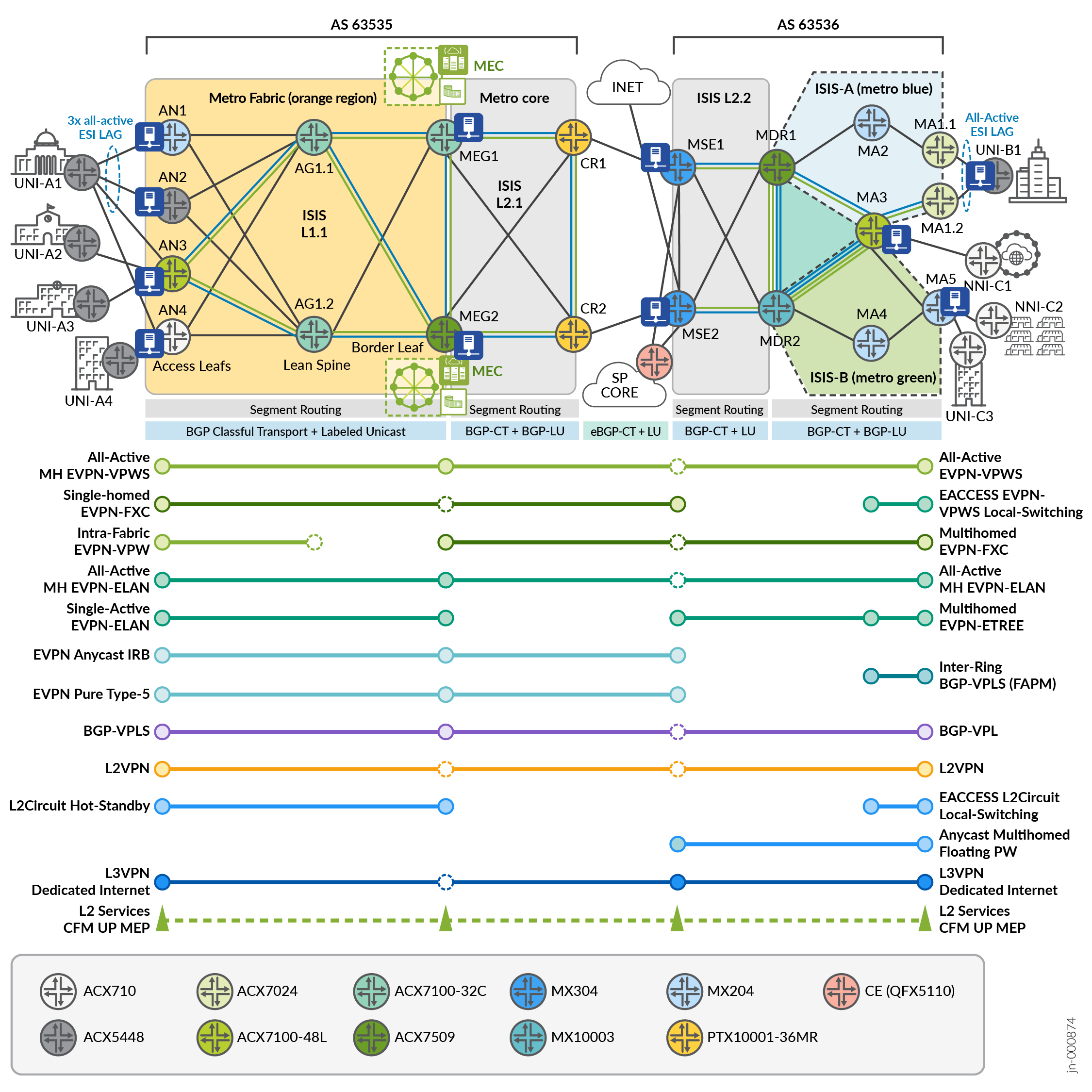
The above diagram details service instantiation points throughout the network. In the services schematic, solid circles represent points of termination, whereas empty dotted-line circles indicate passthrough or inter-AS points of the network. For more information on specific device participation, see Table 1 .
| Topology Definitions | Role | Device |
|---|---|---|
| Access Leaf | AN | ACX7100-48L (DUT), ACX710, ACX5448, MX204 |
| Lean Spine | AG1 | ACX7100-32C |
| Lean Edge Border Leaf | MEG | Metro Edge Gateway: ACX7509 (DUT), ACX7100-32C (DUT) |
| Core | CR | PTX10001-36MR |
| Multiservices Edge | MSE | MX304 (DUT) |
| Metro Distribution Router | MDR | MX10003, ACX7509 (DUT) |
| Metro Access Node | MA | ACX7024 (DUT), ACX7100-48L (DUT), MX204 (DUT) |
Service Providers are increasingly deploying or migrating to EVPN as a more capable solution under a single technology umbrella compared to fragmented traditional VPN services, such as L2Circuit, VPLS, and L2VPN. However, operators continue to require legacy support as both standalone and coexisting solutions. This JVD considers a range of modern and traditional Carrier Ethernet services, creating a comparative performance analysis and providing methodologies to modernize legacy protocols.
The validation consists of the standard service types:
- E-LINE
- E-LAN
- E-TREE
- ACCESS E-LINE (formerly E-Access)
Metro EBS JVD additionally includes Layer 3 IPVC service types, but this is outside the scope of MEF 3.0. EVPN-ELAN with Route-Type 5 is included as an L3+L2 VPN service, with the validation focusing on the L2 aspect.
This JVD offers E-Line, E-LAN, and E-Tree services with options for single-homing and active-active multi-homing nodes to maximize service availability. Service type conformance, defined by MEF, utilizes the following attributes and testing requirements for reliable and consistent Ethernet connectivity across diverse network environments.
- UNI Service Attributes define the subscriber's interface characteristics in the service provider network.
- EVC per UNI Service Attributes distinguishes how the EVC functions at each UNI.
- EVC Service Attributes define the EVC characteristics critical to service functionality.
- CE-VLAN ID and EVC map between UNIs
- EPL, EP-LAN, and EP-Tree: All CE-VLAN IDs, CoS assignments, as well as priority-tagged and untagged frames are included within a single EVC.
- EVPL, EVP-LAN, and EVP-Tree: A single CE-VLAN ID in the EVC, allowing for all CoS assignments.
- L2CP functions identify frames that are tunneled (forwarded) or discarded within the service.
- Service Operations, Administration, and Maintenance (SOAM) functions identify frames that must be tunneled (CCM, LBM, LTM, LTR at MEG levels 5 and 6) for operational continuity.
- Preservation of CE-VLAN IDs and CoS ensures that customer-defined VLAN IDs and CoS priorities are maintained across the network.
In addition, MEF compliance testing includes specific traffic and port characteristics to validate service quality, including expected disposition settings explained in the Key Service Attributes section:
- Traffic Types: Unicast, multicast, and broadcast traffic behavior
- Frame Tagging: Proper handling of tagged and untagged Ethernet frames
Metro as a Service: E-LINE
The following sections describe how MEF framework is leveraged in the JVD to deliver Metro as a Service (MaaS) solution. This section explains the E-Line portion of the MEF 3.0 validation.
The Subscriber Ethernet Services Definition 6.2/6.3 technical specification defines the E-Line service type as a point-to-point EVC connecting two User-Network Interfaces (UNIs). This service type provides dedicated, private, and reliable Ethernet communication between two endpoints.

Basic E-Line connects two UNIs to deliver a best-effort service with symmetrical bandwidth without performance guarantees.
In more advanced E-Line implementations, a more diverse service offer might include:
- Differing bandwidth rates between UNIs.
- Multiple Class of Service (CoS) profiles for tailoring service levels.
- Performance objectives measuring Frame Delay (FD), Inter-Frame Delay Variation (IFDV), and Frame Loss Ratio (FLR) to establish availability metrics.
- Service Multiplexing at one or both UNIs, enabling multiple point-to-point EVCs.
E-Line services come in two main variations:
- Ethernet Private Line (EPL) is a port-based point-to-point “all-to-one bundling” service providing a dedicated, transparent data path. Subscribers maintain full control over their network infrastructure with the flexibility to create and manage multiple point-to-point connections over a single UNI, typically using VLAN separation. CE-VLAN IDs and CE-VLAN CoS markings are preserved end-to-end. EPL is ideal for applications requiring full Ethernet frame delivery between locations. Depending on SLAs, additional performance objectives may include low-latency guarantees, high reliability, bandwidth allocation, and so forth.
- Ethernet Virtual Private Line (EVPL) is similar to EPL but supports service multiplexing (VLAN-based), allowing multiple services to share the same physical interface at a UNI. EVPL enables multiple EVCs on one or both of the UNIs, providing greater flexibility for delivering multiple point-to-point connections over a single UNI. EVPL is well-suited for organizations that need scalable, segmented connectivity with customized service levels across diverse applications.
Depending on the required CoS, these services can be tailored to meet specific performance criteria. The service attributes and their values are detailed in MEF specifications, with specific constraints outlined for E-Line services to ensure performance consistency.
E-LINE Point-to-Point Services
The protocol suite of point-to-point E-LINE services covered by the JVD includes EVPN-VPWS, EVPN Flexible Cross Connect (FXC), BGP-VPLS (as a point-to-point service), L2Circuit, Floating PW, and L2VPN. The profile implements 11 distinct E-Line use cases to deliver different connectivity options. Each use case has approximately 500 MEF-related test cases executed as part of the validation. The key service categories under the test include:
- Functional Service Attributes and Parameters
- Layer 2 Control Protocol Frame Behaviors
- Service OAM Functionalities
- Bandwidth Profile Attributes and Parameters
- Service Performance Attributes and Parameters

Multiple permutations of the following service instantiation are delivered:
- Intra-Fabric
- Inter-AS
- Inter-Ring
- Single-homing and Multihoming
- VLAN Aware and VLAN Unaware
Each VPN type can support multiple combinations of MEF service attributes. This flexibility is demonstrated, but the JVD does not attempt to include every possible combination. There are additional valid options for each VPN service type that can be leveraged, depending on the service objectives.
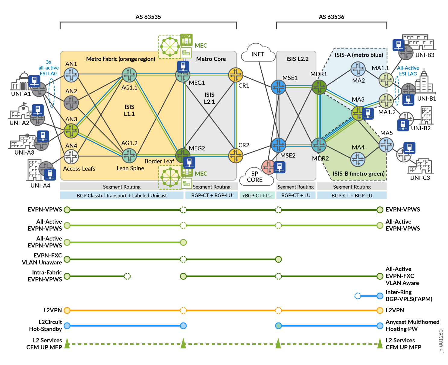
The lab topology includes service instantiation points illustrated in Figure 4 for E-Line services, covered by the corresponding MEF test cases. Iometrix test probes are placed throughout the topology for conducting the end-to-end validation.
| Index | Service Type | VPN Type | High Availability | Service Instantiation | Endpoints |
|---|---|---|---|---|---|
| 1 | E-Line | EVPN-VPWS Port Based | Single-Homed | Inter-AS Fabric to Ring | AN3, MA1.1 |
| 2 | E-Line | EVPN-VPWS VLAN-based | Active-Active Multihoming | Inter-AS Fabric to Ring | AN1, AN2, AN3, MA1.1, MA1.2 |
| 3 | E-Line | EVPN-VPWS VLAN-based | Single-Homed | Intra-Fabric | AN3, AN4 |
| 4 | E-Line | EVPN-VPWS VLAN-based | Active-Active Multihoming | Metro Fabric | AN3, MEG1, MEG2 |
| 5 | E-Line | EVPN Flexible Cross-Connect VLAN Aware | Active-Active Multihoming | Inter-AS MEG to Ring | MEG1. MEG2, MA1.1, MA1.2 |
| 6 | E-Line | EVPN Flexible Cross-Connect VLAN Unaware | Single-Homed | Inter-AS Fabric to MSE | AN3, MSE1 |
| 7 | E-Line | Layer 2 Circuit | Hot-Standby | Metro Fabric | AN3, MEG1, MEG2 |
| 8 | E-Line | L2VPN Port Based | Single-Homed | Inter-AS Fabric to Ring | AN3, MA5 |
| 9 | E-Line | L2VPN VLAN-based | Single-Homed | Inter-AS Fabric to Ring | AN3, MA5 |
| 10 | E-Line | BGP-VPLS VPWS | Single-Homed | Inter-Rings | MA5, MA1.2 |
| 11 | E-Line | EVPN Floating Pseudowire | Anycast | Metro Ring | MSE1, MSE2, MA1.2 |
Every VPN service included in the JVD is designed with the purpose of delivering crucial metro functionality and connectivity objectives. The services featured in Table 2 are further explained in Table 3 with use cases.
|
Matching Index |
E-Line EVPL | Metro Use Case |
|---|---|---|
| [ 2 ] | EVPN-VPWS | EVPN-VPWS with EVI spanning up to three PEs AN1 (MX204), AN2 (ACX5448), and AN3 (ACX7100-48L) to connect the CE (UNI-A1) Ethernet Segment (ES) with all-active ESI UNI resiliency. The E-Line EVPN service is extended end-to-end with Inter-AS support terminating into the EVPN EVI spanning two PEs MA1.1 (ACX7024) and MA1.2 (ACX7024) with an all-active ESI connecting the UNI-B1 ES. |
| [ 3 ] | EVPN-VPWS | EVPN-VPWS, as a Metro Fabric E-Line service, supports intra-fabric communications between AN3 (ACX7100-48L) and AN4 (ACX710) with traffic flows optimized to be contained within the spine nodes AG1.1/AG1.2 (ACX7100-32C). |
| [ 4 ] | EVPN-VPWS | EVPN-VPWS establishes an active-active high availability service connection between AN3 (ACX7100-48L) to MEG1 (ACX7100-32C) and MEG2 (ACX7509) to provide UNI-A3 connectivity into the Multiaccess Edge Computing complex over an all-active ESI. |
| [ 5 ] |
EVPN-FXC VLAN-Aware |
EVPN Flexible Cross Connect (FXC) as a VLAN Aware service is established between MA1.1/MA1.2 (ACX7024) with all-active ESI attachment circuits supporting multiple UNI ports and terminating on an active-active high availability connection with MEG1 (ACX7100-32C) and MEG2 (ACX7509). This Inter-AS service allows simplistic VLAN aggregation options with the ability to support one or more VLAN stacks per ESI for MEC access. |
| [ 6 ] |
EVPN-FXC VLAN-Unaware |
EVPN Flexible Cross Connect (FXC) as a VLAN Unaware service is established between AN3 (ACX7100-48L) to MSE1 (MX304), connecting UNI-A2 into a QinQ infrastructure. This Inter-AS service allows simplistic VLAN aggregation options with a shared-state ESI. |
| [ 7 ] | L2Circuit | Layer 2 Circuit (L2Circuit) establishes an active-passive (hot-standby) connection between AN3 and MEG1 (active) and MEG2 (hot-standby). This traditional service (aka Martini) is extended to support the modern requirements of the network for accessing MEC resources. |
| [ 9 ] | L2VPN | L2VPN is a traditional BGP Layer 2 service (aka Kompella), establishing the Inter-AS connection between AN3 (ACX7100-48L) and MA4 (MX204). |
| [ 10 ] | BGP-VPLS | BGP-VPLS is leveraged as a point-to-point service connecting MA5 (MX204) with MA1.2 (ACX7024) over the multi-ring topology with optimizations to traverse the service-unaware MDR nodes. |
| [ 11 ] | EVPN Floating PW | EVPN Floating Pseudowire is a reimagined Static L2Circuit service utilizing a Segment Routing Anycast-SID for active-active termination on MSE1 and MSE2 (MX304). Using an anycast service label allows traffic to be load-shared over the ring. The floating PW service allows VLAN aggregation with selective stitching into EVPN-ELAN containers on the MSEs. The virtual ESI established with the MX pseudowire interface (ps) allows for an all-active vESI facing the ring segment. |
|
Matching Index |
E-Line EPL | Metro Use Case |
|---|---|---|
| [ 1 ] | EVPN-VPWS | EVPN-VPWS port-based service supports a point-to-point multidomain Inter-AS connection between AN3 to MA1.1. This enables UNI-A3 flexible connectivity with the UNI-B3 site. |
| [ 8 ] | L2VPN | L2VPN port-based service is delivered between AN3 (ACX7100-48L) and MA5 (MX204) connecting UNI-A3 with UNI-C3. |
For E-Line configurations used in this JVD and in Metro EBS JVD , see Juniper GitHub Repository or contact your Juniper representative.
E-Line: EVPN-VPWS Example
E-Line EVPN-VPWS vlan-based services are included with several permutations in the validation (explained in Table 3 and throughout section E-LINE Point-to-Point Service E-LINE Point-to-Point Services). In the following sample configuration, MEG1 and MEG2 provide an all-active ESI termination for EVPN-VPWS services.
              MEG1 (ACX7100-32C)
interfaces {
    ae67 {
        unit 4000 {
            encapsulation vlan-ccc;
            vlan-id 4000;
            esi {
                00:40:11:11:21:22:01:00:00:01;
                all-active;
            }
            family ccc {
                filter {
                    input f_eline-evpn-vpws;
                }
            }
        }
    }
}
routing-instances {
    evpn_group_edge_4000 {
        instance-type evpn-vpws;
        protocols {
            evpn {
                interface ae67.4000 {
                    vpws-service-id {
                        local 2;
                        remote 1;
                    }
                }
            }
        }
        interface ae67.4000;
        route-distinguisher 10.0.0.6:33300;
        vrf-export evpn_group_edge_4000;
        vrf-target target:63535:33300;
    }
}
MEG2 (ACX7509)
interfaces {
    ae67 {
        unit 4000 {
            encapsulation vlan-ccc;
            vlan-id 4000;
            esi {
                00:40:11:11:21:22:01:00:00:01;
                all-active;
            }
            family ccc {
                filter {
                    input f_eline-evpn-vpws;
                }
            }
        }
    }
}
routing-instances {
    evpn_group_edge_4000 {
        instance-type evpn-vpws;
        protocols {
            evpn {
                interface ae67.4000 {
                    vpws-service-id {
                        local 2;
                        remote 1;
                    }
                }
            }
        }
        interface ae67.4000;
        route-distinguisher 10.0.0.7:33300;
        vrf-export evpn_group_edge_4000;
        vrf-target target:63535:33300;
    }
}
For more information on EVPN-VPWS E-Line configurations, see Juniper GitHub Repository .
E-Line: EVPN-FXC VLAN Aware Example
EVPN-VPWS Flexible Cross-Connect (FXC), enables multiplexing a large number of attachment circuits across multiple interfaces onto a single VPWS service tunnel. All attachment circuits bundled by the FXC instance share the same MPLS label and service tunnel. With VLAN Aware FXC, service multiplexing can support multiple Ethernet Segments with distinct high availability. Although the same service label is leveraged for all attachment circuits, an Ethernet A-D is advertised or withdrawn per EVI route for each attachment circuit.
E-Line EVPN-VPWS Flexible Cross Connect (FXC) VLAN Aware services (explained in section E-LINE Point-to-Point Services ) are established between MA1.1/MA1.2 (ACX7024) with all-active ESI attachment circuits supporting multiple UNI ports and terminating an active-active high availability connection with MEG1 (ACX7100-32C) and MEG2 (ACX7509). This Inter-AS service allows simplistic VLAN aggregation options with the ability to support one or more VLAN stacks per ESI for MEC access.
In the sample configuration below, MA1.1 and MA1.2 provide all-active ESI termination for EVPN-FXC services. FXC is commonly leveraged with Pseudowire Headend Termination (PWHT). For this example, it is point-to-point with strictly FXC at the terminating points.
              MA1.1 (ACX7024)
interfaces {
    ae12 {
        unit 4002 {
            encapsulation vlan-ccc;
            vlan-id 4002;
            input-vlan-map {
                push;
                vlan-id 3400;
            }
            output-vlan-map pop;
            esi {
                00:10:55:11:50:12:02:00:00:00;
                all-active;
            }
            family ccc {
                filter {
                    input f_eline-evpn-vpws;
                }
            }
        }
        unit 4001 {
            encapsulation vlan-ccc;
            vlan-id 4001;
            input-vlan-map {
                push;
                vlan-id 3000;
            }
            output-vlan-map pop;
            esi {
                00:10:55:11:50:12:01:00:00:00;
                all-active;
            }
            family ccc {
                filter {
                    input f_eline-evpn-vpws;
                }
            }
        }
    }
}
routing-instances {
    evpn_vpws_fxc_aware {
        instance-type evpn-vpws;
        protocols {
            evpn {
                interface ae12.4001 {
                    vpws-service-id {
                        local 2;
                        remote 1;
                    }
                }
                interface ae12.4002 {
                    vpws-service-id {
                        local 22;
                        remote 11;
                    }
                }
                flexible-cross-connect-vlan-aware;
            }
        }
        interface ae12.4001;
        interface ae12.4002;
        route-distinguisher 10.0.0.17:5501;
        vrf-export evpn_vpws_fxc_aware;
        vrf-target target:63536:55100;
    }
}
MA1.2 (ACX7024)
interfaces {
    ae12 {
        unit 4002 {
            encapsulation vlan-ccc;
            vlan-id 4002;
            input-vlan-map {
                push;
                vlan-id 3400;
            }
            output-vlan-map pop;
            esi {
                00:10:55:11:50:12:02:00:00:00;
                all-active;
            }
            family ccc {
                filter {
                    input f_eline-evpn-vpws;
                }
            }
        }
        unit 4001 {
            encapsulation vlan-ccc;
            vlan-id 4001;
            input-vlan-map {
                push;
                vlan-id 3000;
            }
            output-vlan-map pop;
            esi {
                00:10:55:11:50:12:01:00:00:00;
                all-active;
            }
            family ccc {
                filter {
                    input f_eline-evpn-vpws;
                }
            }
        }
    }
}
routing-instances {
    evpn_vpws_fxc_aware {
        instance-type evpn-vpws;
        protocols {
            evpn {
                interface ae12.4001 {
                    vpws-service-id {
                        local 2;
                        remote 1;
                    }
                }
                interface ae12.4002 {
                    vpws-service-id {
                        local 22;
                        remote 11;
                    }
                }
                flexible-cross-connect-vlan-aware;
            }
        }
        interface ae12.4001;
        interface ae12.4002;
        route-distinguisher 10.0.0.18:5501;
        vrf-export evpn_vpws_fxc_aware;
        vrf-target target:63536:55100;
    }
}
For more information on EVPN-FXC E-Line configurations, see Juniper GitHub Repository .
E-Line: EVPN-FXC VLAN Unaware Example
EVPN-VPWS Flexible Cross-Connect (FXC), enables multiplexing a large number of attachment circuits across multiple interfaces onto a single VPWS service tunnel. All attachment circuits bundled by the FXC instance share the same MPLS service label and service tunnel. With VLAN Unaware FXC, a single Ethernet A-D is advertised or withdrawn for the entire bundle of attachment circuits. The route is withdrawn only when all the attachment circuits are down.
E-Line EVPN-VPWS FXC VLAN Unaware services (explained in the E-LINE Point-to-Point Services section) are established between AN3 (ACX7100-48L) to MSE1 (MX304), connecting UNI-A2 into a QinQ infrastructure. This Inter-AS service allows simplistic VLAN aggregation options across a shared-state instance.
In the sample configuration below, AN3 presents two logical interfaces with service multiplexed Attachment Circuits (AC) bundled in a single EVI. An ESI could be extended for high availability with all ACs sharing EVI state. FXC is commonly leveraged with Pseudowire Headend Termination (PWHT). For this example, it is point-to-point with strictly FXC at the terminating points.
              AN3 (ACX7100-48L)
interfaces {
    et-0/0/13 {
        flexible-vlan-tagging;
        encapsulation flexible-ethernet-services;
        unit 4007 {
            encapsulation vlan-ccc;
            vlan-id 4007;
            family ccc {
                filter {
                    input f_eline-evpn-vpws;
                }
            }
        }
        unit 4008 {
            encapsulation vlan-ccc;
            vlan-id 4008;
            family ccc {
                filter {
                    input f_eline-evpn-vpws;
                }
            }
        }
    }
}
routing-instances {
    evpn_group_4007 {
        instance-type evpn-vpws;
        protocols {
            evpn {
                flexible-cross-connect-vlan-unaware;
                group fxc {
                    interface et-0/0/13.4007;
                    interface et-0/0/13.4008;
                    interface et-0/0/1.4007;
                    interface et-0/0/1.4008;
                    service-id {
                        local 1;
                        remote 2;
                    }
                }
            }
        }
        route-distinguisher 10.0.0.2:40001;
        vrf-target target:63535:40001;
    }
}
MSE1 (MX304)
interfaces {
    xe-0/0/13:2 {
        flexible-vlan-tagging;
        encapsulation flexible-ethernet-services;
        unit 4007 {
            encapsulation vlan-ccc;
            vlan-id 4007;
            family ccc {
                filter {
                    input f_eline-evpn-vpws;
                }
            }
        }
        unit 4008 {
            encapsulation vlan-ccc;
            vlan-id 4008;
            family ccc {
                filter {
                    input f_eline-evpn-vpws;
                }
            }
        }
    }
}
routing-instances {
    evpn_group_4007 {
        instance-type evpn-vpws;
        protocols {
            evpn {
                flexible-cross-connect-vlan-unaware;
                group fxc {
                    interface xe-0/0/13:2.4007;
                    interface xe-0/0/13:2.4008;
                    service-id {
                        local 2;
                        remote 1;
                    }
                }
            }
        }
        route-distinguisher 10.0.0.10:40001;
        vrf-target target:63535:40001;
    }
}
For more information on EVPN-FXC E-Line configurations, see Juniper GitHub Repository .
E-Line: Layer 2Circuit Example
Layer 2 Circuit (L2Circuit) establishes an active-passive (hot-standby) connection between AN3 and MEG1 (active) and MEG2 (hot-standby). This traditional service (aka Martini) is extended to support the modern requirements of the network for accessing MEC resources. Optionally, vlan normalization and Flow-Aware Transport Pseudowire (FAT-PW) label load-balancing are included. AN3 (ACX7100-48L) establishes the primary and backup remote PEs. MEG1 and MEG2 are configured with hot-standby-vc-on to enable hot-standby pseudowire upon receipt of the status-TLV. The solution is further explained in the E-LINE Point-to-Point Services section.
              AN3 (ACX7100-48L)
interfaces {
    et-0/0/13 {
        flexible-vlan-tagging;
        encapsulation flexible-ethernet-services;
        unit 4006 {
            encapsulation vlan-ccc;
            vlan-id 4006;
            input-vlan-map {
                push;
                vlan-id 1000;
            }
            output-vlan-map pop;
            family ccc {
                filter {
                    input f_eline-evpn-vpws;
                }
            }
        }
    }
}
protocols {
    l2circuit {
        neighbor 10.0.0.6 {
            interface et-0/0/13.4006 {
                virtual-circuit-id 2006;
                control-word;
                flow-label-transmit;
                flow-label-receive;
                encapsulation-type ethernet-vlan;
                ignore-mtu-mismatch;
                pseudowire-status-tlv;
                backup-neighbor 10.0.0.7 {
                    virtual-circuit-id 3333;
                    hot-standby;
                }
            }
        }
    }
}
MEG1 (ACX7100-32C) and MEG2 (ACX7509)
interfaces {
    et-2/0/4 {
        flexible-vlan-tagging;
        encapsulation flexible-ethernet-services;
        unit 4006 {
            encapsulation vlan-ccc;
            vlan-id 4006;
            input-vlan-map {
                push;
                vlan-id 1000;
            }
            output-vlan-map pop;
            family ccc {
                filter {
                    input f_eline-evpn-vpws;
                }
            }
        }
    }
}
protocols {
    l2circuit {
        neighbor 10.0.0.2 {
            interface et-2/0/4.4006 {
                virtual-circuit-id 3333;
                control-word;
                flow-label-transmit;
                flow-label-receive;
                encapsulation-type ethernet-vlan;
                ignore-encapsulation-mismatch;
                ignore-mtu-mismatch;
                pseudowire-status-tlv {
                    hot-standby-vc-on;
                }
            }
        }
    }
For more information on L2Circuit E-Line configurations, see Juniper GitHub Repository .
E-Line: Layer 2 VPN Example
Layer 2 VPN is a traditional BGP Layer 2 service (aka Kompella), establishing the Inter-AS connection between AN3 (ACX7100-48L) and MA5 (MX204). The solution is further explained in the E-LINE Point-to-Point Services section
              AN3 (ACX7100-48L)
interfaces {
    et-0/0/13 {
        flexible-vlan-tagging;
        encapsulation flexible-ethernet-services;
        unit 200 {
            encapsulation vlan-ccc;
            vlan-id 200;
            family ccc {
                filter {
                    input f_eline-evpn-vpws;
                }
            }
        }
    }
}
routing-instances {
    l2vpn_group_200 {
        instance-type l2vpn;
        protocols {
            l2vpn {
                site r2 {
                    interface et-0/0/13.200 {
                        remote-site-id 1119;
                    }
                    site-identifier 1102;
                }
                encapsulation-type ethernet-vlan;
                no-control-word;
            }
        }
        interface et-0/0/13.200;
        route-distinguisher 63535:102000;
        vrf-target target:63535:102000;
    }
}
For more information on L2VPN E-Line configurations, see Juniper GitHub Repository .
E-Line: BGP-VPLS Example
BGP-VPLS is leveraged as a point-to-point service connecting MA5 (MX204) with MA1.2 (ACX7024) over the multi-ring topology with optimizations to traverse the service-unaware MDR nodes. Although not mandatory, the label-block-size can be reduced from the default of eight for label space savings.
              MA1.2 (ACX7024)
interfaces {
    et-0/0/12 {
        vlan-tagging;
        encapsulation flexible-ethernet-services;
        unit 4005 {
            encapsulation vlan-bridge;
            vlan-id 4005;
            family ethernet-switching {
                filter {
                    input f_elan-evpn;
                }
            }
        }
    }
}
routing-instances {
    vpls_group_4005 {
        instance-type virtual-switch;
        protocols {
            vpls {
                site r18 {
                    site-identifier 2;
                }
                service-type single;
                site-range 2;
                label-block-size 2;
                no-tunnel-services;
            }
        }
        route-distinguisher 10.0.0.18:44444;
        vrf-target target:64535:44444;
        vlans {
            vlan4005 {
                interface et-0/0/12.4005;
            }
        }
    }
}
MA5 (MX204)
interfaces {
    xe-0/1/0 {
        vlan-tagging;
        encapsulation flexible-ethernet-services;
        unit 4005 {
            encapsulation vlan-bridge;
            vlan-id 4005;
            family bridge {
                filter {
                    input f_elan-evpn;
                }
            }
        }
    }
}
routing-instances {
    vpls_group_4005 {
        instance-type virtual-switch;
        protocols {
            vpls {
                site r19 {
                    site-identifier 1;
                }
                site-range 2;
                label-block-size 2;
                no-tunnel-services;
            }
        }
        bridge-domains {
            vlan4005 {
                vlan-id 4005;
                interface xe-0/1/0.4005;
                bridge-options {
                    no-normalization;
                }
            }
        }
        route-distinguisher 10.0.0.19:44444;
        vrf-target target:64535:44444;
    }
}
For more information on BGP-VPLS E-Line configurations, see Juniper GitHub Repository .
E-Line: EVPN Floating Pseudowire Example
EVPN Floating Pseudowire (PW) is a reimagined Static L2Circuit service utilizing a Segment Routing Anycast-SID for active-active termination on MSE1 and MSE2 (MX304). Using an anycast service label allows traffic to be load-shared over the Metro Ethernet ring. The floating PW service allows VLAN aggregation with selective stitching into EVPN-ELAN containers on the MSEs. The virtual ESI established with the MX pseudowire interface (ps) allows for an all-active vESI facing the ring segment.
The basic construct of the Floating PW service establishes a static L2Circuit from MA1.2 (ACX7024) towards an Anycast IP Gateway associated with an Anycast-SID terminating on both MSE1 and MSE2. The L2Circuit is terminated on the MX PS transport interface (ps22.0 in the configuration below). The associated pseudowire service interface (ps22.4004) is stitched into an EVPN instance, establishing the virtual ESI facing toward the access node. This vESI operates as all-active and signaled appropriately between MSE1/2, establishing the designated and backup forwarder based on default MOD election. EVPN signaling is separated from anycast functionalities and uses local (unique) loopbacks for MSE1/2.
An additional optimization may include a conditional route policy applied to ISIS and BGP export policies to track the state of the transport interface (ps22.0).
              MA1.2 (ACX7024)
interfaces {
    et-0/0/12 {
        flexible-vlan-tagging;
        encapsulation flexible-ethernet-services;
        unit 4004 {
            encapsulation vlan-ccc;
            vlan-id 4004;
            family ccc {
                filter {
                    input f_eline-evpn-vpws;
                }
            }
        }
    }
}
protocols {
    l2circuit {
        neighbor 1.1.10.10 {
            interface et-0/0/12.4004 {
                static {
                    incoming-label 1000022;
                    outgoing-label 1000022;
                }
                virtual-circuit-id 10120;
                encapsulation-type ethernet-vlan;
            }
        }
    }
}
MSE1 (MX304)
interfaces {
    ps22 {
        anchor-point {
            lt-0/0/0;
        }
        vlan-tagging;
        encapsulation flexible-ethernet-services;
        unit 0 {
            encapsulation ethernet-ccc;
        }
        unit 4004 {
            encapsulation vlan-bridge;
            vlan-id 4004;
            esi {
                00:11:11:11:44:11:11:30:02:0a;
                all-active;
            }
        }
    }
    ae10 {
        unit 4004 {
            encapsulation vlan-bridge;
            vlan-id 4004;
            esi {
                00:11:11:11:11:44:11:30:01:0a;
                all-active;
            }
            family bridge {
                filter {
                    input f_elan-evpn;
                }
            }
        }
    }
}
routing-instances {
    4004-evpn-floating-pw {
        instance-type evpn;
        protocols {
            evpn;
        }
        vlan-id 4004;
        interface ae10.4004;
        interface ps22.4004;
        route-distinguisher 10.0.0.10:40004;
        vrf-target target:4004:4004;
    }
}
protocols {
    l2circuit {
        neighbor 10.0.0.18 {
            interface ps22.0 {
                static {
                    incoming-label 1000022;
                    outgoing-label 1000022;
                }
                virtual-circuit-id 10120;
                encapsulation-type ethernet-vlan;
            }
        }
    }
}
policy-options {
        condition Floating-PW-Condition {
        if-route-exists {
            address-family {
                ccc {
                    ps22.0;
                    table mpls.0;
                }
            }
        }
    }
}
MSE2 (MX304)
interfaces {
    ps22 {
        anchor-point {
            lt-0/0/0;
        }
        vlan-tagging;
        encapsulation flexible-ethernet-services;
        unit 0 {
            encapsulation ethernet-ccc;
        }
        unit 4004 {
            encapsulation vlan-bridge;
            vlan-id 4004;
            esi {
                00:11:11:11:44:11:11:30:02:0a;
                all-active;
            }
        }
    }
    ae10 {
        unit 4004 {
            encapsulation vlan-bridge;
            vlan-id 4004;
            esi {
                00:11:11:11:11:44:11:30:01:0a;
                all-active;
            }
            family bridge {
                filter {
                    input f_elan-evpn;
                }
            }
        }
    }
}
routing-instances {
    4004-evpn-floating-pw {
        instance-type evpn;
        protocols {
            evpn;
        }
        vlan-id 4004;
        interface ae10.4004;
        interface ps22.4004;
        route-distinguisher 10.0.0.11:40004;
        vrf-target target:4004:4004;
    }
}
protocols {
    l2circuit {
        neighbor 10.0.0.18 {
            interface ps22.0 {
                static {
                    incoming-label 1000022;
                    outgoing-label 1000022;
                }
                virtual-circuit-id 10120;
                encapsulation-type ethernet-vlan;
            }
        }
    }
}
policy-options {
        condition Floating-PW-Condition {
        if-route-exists {
            address-family {
                ccc {
                    ps22.0;
                    table mpls.0;
                }
            }
        }
    }
}
For more information on Floating Pseudowire E-Line configurations, see Juniper GitHub Repository .
Metro as a Service: E-LAN
The following sections describe how MEF framework is leveraged in the JVD to deliver Metro as a Service (MaaS) solution. This section explains the E-LAN portion of the MEF 3.0 validation. The Subscriber Ethernet Services Definition 6.2/6.3 technical specification defines the E-LAN service type as a multipoint-to-multipoint EVC. E-LAN services allow communication between multiple locations by connecting UNIs, enabling any site to communicate directly with any other site within the network. E-LAN is designed to simulate the functionality of a traditional Local Area Network (LAN) over a Metro Ethernet Network (MEN).
Multipoint-to-multipoint offers flexible and scalable solutions for enterprises that need to interconnect multiple branch offices, data centers, or remote sites.
Service multiplexing is an important E-LAN feature capability, allowing multiple Ethernet services to be delivered over a single physical interface (UNI). A UNI can simultaneously support both E-LAN services connecting multiple locations and an E-Line service forming point-to-point connections. The ability to multiplex different services across the same interface is an important goal of supporting a flexible network design.
E-LAN implements similar service performance categories to E-Line, wherein the basic imposition may include a best-effort service without performance guarantees. This means data transmission is not prioritized, and there are no assurances for latency or packet loss thresholds. In more advanced implementations, Service-Level Objectives (SLOs) are established to ensure key performance metrics are delivered:
- Differing bandwidth rates between UNIs
- Multiple Class of Service (CoS) profiles for tailoring service levels
- Performance objectives measuring Frame Delay (FD), Inter-Frame Delay Variation (IFDV), and Frame Loss Ratio (FLR) to establish availability metrics
- Service Multiplexing at one or more UNIs, enabling flexibility for multiple multipoint-to-multipoint E-LAN services and/or in parallel with point-to-point E-Line EVCs
These metrics ensure that the network meets specific performance levels, making it suitable for more critical applications that require reliable data transmission, such as voice, video, or financial transactions.
E-LAN services include two main variations determined by the degree of control delegated between the service provider and customer end user:
- Ethernet Private LAN (EP-LAN) is a port-based multipoint-to-multipoint “all-to-one bundling” service providing a dedicated and private, transparent data path. All traffic on the physical port is mapped to a single EVC. EP-LAN allows subscribers full control over their network infrastructure with the flexibility to create and manage site-to-site connectivity options. CE-VLAN IDs and CE-VLAN CoS markings are preserved end-to-end.
- Ethernet Virtual Private LAN (EVP-LAN) is similar to EP-LAN but supports service multiplexing and shared bandwidth across the network. EVP-LAN enables multiple EVCs on one or more UNIs, providing greater flexibility for delivering multiple multipoint-to-multipoint E-LAN services and/or in parallel with point-to-point E-Line EVCs over a single UNI. Subscribers and/or traffic flows can be mapped to specific VLANs with flexible VLAN ID preservation and QoS mapping.
E-LAN services offer a range of possibilities for enterprises looking to interconnect their facilities in an efficient and effective manner. The detailed service attributes and configurations, as outlined in MEF technical specifications, provide a foundation for customizing the service to meet varying business needs.
The Iometrix MEF 3.0 validation covers the critical functionality required to deliver E-LAN services and provide robust, flexible, and scalable solutions for organizations that require reliable multipoint-to-multipoint Ethernet connectivity. Leveraging the Metro EBS JVD solution architecture enables the ability to scale from best-effort services to high-performance, guaranteed service delivery with strict performance objectives.
E-LAN Multipoint-to-Multipoint Services
The protocol suite of multipoint-to-multipoint E-LAN services covered by the JVD includes EVPN-ELAN and BGP-VPLS. The profile implements five distinct E-LAN use cases to deliver different connectivity options. Each use case includes approximately 500-1250 MEF-related test cases executed as part of the validation. The key service categories under the test include:
- Functional Service Attributes and Parameters
- Layer 2 Control Protocol Frame Behaviors
- Service OAM Functionalities
- Bandwidth Profile Attributes and Parameters
- Service Performance Attributes and Parameters

Multiple permutations of the following service instantiation are delivered:
- Intra-Fabric
- Inter-AS
- Inter-Ring
- Single-homing and Multihoming
- VLAN Aware and VLAN Unaware
Each VPN type can support multiple combinations of MEF service attributes. This flexibility is demonstrated, but the JVD does not attempt to include every possible combination. There are additional valid options for each VPN service type that can be leveraged, depending on the service objectives.
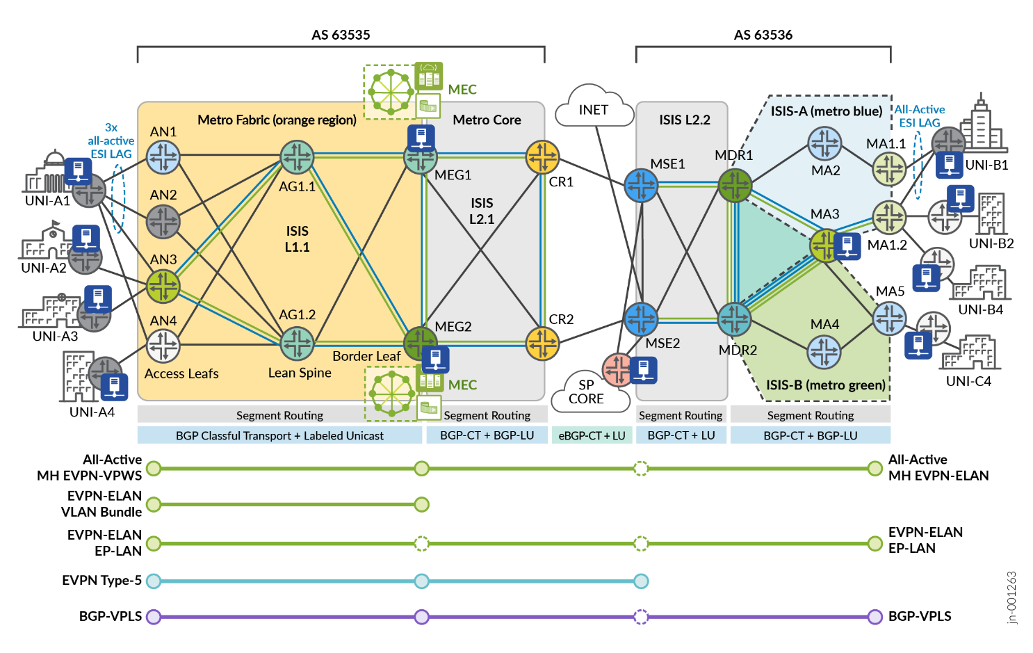
The lab topology includes service instantiation points illustrated in Figure 7 for E-LAN services, covered by the corresponding MEF test cases. Iometrix test probes are placed throughout the topology for conducting end-to-end validation.
| Index | Service Type | VPN Type | High Availability | Service Instantiation | Endpoints |
|---|---|---|---|---|---|
| 1 | E-LAN | EVPN-ELAN Port Based | Single-Homed | Inter-AS Fabric to Ring | AN3, MA1.2, MA5 |
| 2 | E-LAN | EVPN-ELAN VLAN-based | Active-Active Multihoming | Inter-AS Fabric to Ring | AN1, AN2, AN3, MEG1. MEG2, MA1.1, MA1.2 |
| 3 | E-LAN | EVPN-ELAN VLAN Bundle | Active-Active Multihoming | Metro Fabric | AN3, MEG1. MEG2 |
| 4 | E-LAN | EVPN-ELAN Type 5 | Active-Active Multihoming | Inter-AS Fabric to MSE | AN3, MEG1, MEG2, MSE1, MSE2 |
| 5 | E-LAN | BGP-VPLS | Single-Homed | Inter-AS Fabric to Ring | AN3, MEG2, MA1.2 |
Every VPN service included in the JVD is designed with the purpose of delivering crucial metro functionality and connectivity objectives. The services featured in Table 5 are further explained below.
|
Matching Index |
EVP-LAN | Metro Use Case |
|---|---|---|
| [ 2 ] |
EVPN-ELAN VLAN-based |
EVPN-ELAN VLAN-based service with EVI spanning up to three PEs AN1 (MX204), AN2 (ACX5448), and AN3 (ACX7100-48L) to connect the CE (UNI-A1) Ethernet Segment (ES) with all-active ESI UNI resiliency. The E-LAN EVPN service is extended end-to-end with inter-AS support terminating into the EVPN EVI spanning two PEs MA1.1 (ACX7024) and MA1.2 (ACX7024) with an all-active ESI connecting the UNI-B1 ES. Additional EVPN-ELAN sites include all-active ESI connecting into the Multiaccess Edge Computing infrastructure at MEG1 (ACX7100-32C) and MEG2 (ACX7509). This service allows for a seamless multipoint-to-multipoint LAN with all sites enabled to access MEC resources. |
| [ 3 ] |
EVPN-ELAN VLAN Bundle |
EVPN-ELAN VLAN Bundling establishes an active-active high availability service connection between AN3 (ACX7100-48L) to MEG1 (ACX7100-32C) and MEG2 (ACX7509) to provide UNI-A3 connectivity into the MEC complex over an all-active ESI. EVPN-ELAN VLAN Bundles services support N:1 mapping of CE-VLANs to the EVI Bridge Domain. Service multiplexing is supported with the MEF Bundling attribute selectively enabled or disabled (All-to-One Bundling is disabled). The use case allows the subscriber to curate layer 2 connectivity options between local and remote sites using VLAN matching. This allows the creation of multiple distinct E-LAN and simultaneous E-LINE services between the common networks. |
| [ 4 ] |
EVPN-ELAN Route Type-5 |
With EVPN-ELAN leveraging Route-Type 5, Layer 3 capabilities are extended into the Layer 2 service with IP Prefix advertisement support. This service connects UNI-A3 via AN3 (ACX7100-48L), establishing active-active high availability to MEG1 (ACX7100-32C) and MEG2 (ACX7509 for MEC access, including both Layer 2 and Layer 3 reachability using Virtual Gateway Address (VGA). The use case is further extended to include MSE1 (MX304) as an additional EVPN-ELAN site. |
| [ 5 ] | BGP-VPLS | BGP-VPLS is leveraged as a multipoint-to-multipoint inter-AS service connecting UNI-A2 at AN3 (ACX7100-48L) with the MEC at MEG2 (ACX7509) on the metro fabric and extends the LAN to the metro ring by connecting UNI-B2 site at MA1.2 (ACX7024). |
|
Matching Index |
EP-LAN | Metro Use Case |
|---|---|---|
| [ 1 ] | EVPN-ELAN | EVPN-ELAN port-based service supports an inter-AS LAN service between multidomain inter-AS connections between AN3, MA5, and MA1.2. This enables a flexible and transparent connectivity service between UNI-A4 (AN3), UNI-B4 (MA1.2), and UNI-C4 (MA5). |
For E-LAN configurations used in this JVD and in Metro Ethernet Business Services JVD , see Juniper GitHub Repository or contact your Juniper representative.
E-LAN: EVPN-ELAN VLAN-Based Example
EVPN-ELAN VLAN-based service allows one-to-one mapping of a single broadcast domain to a single bridge domain. Each VLAN is mapped to one EVPN instance (EVI), resulting in a separate bridge table for each VLAN. The example includes attachment circuits from three PEs: AN1 (MX204), AN2 (ACX5448), and AN3 (ACX7100-48L) to connect the CE (UNI-A1) Ethernet Segment (ES) with all-active ESI UNI resiliency.
The E-LAN EVPN service is extended end-to-end with inter-AS support terminating into the EVPN EVI spanning two PEs MA1.1 (ACX7024) and MA1.2 (ACX7024) with an all-active ESI connecting the UNI-B1 ES.
Additional EVPN-ELAN sites include all-active ESI connecting into the Multiaccess Edge Computing (MEC) infrastructure at MEG1 (ACX7100-32C) and MEG2 (ACX7509). This service allows seamless multipoint-to-multipoint LAN with all sites enabled to access MEC resources. For more information, see the E-LAN Multipoint-to-Multipoint Services section.
For brevity, the following sample configuration provides MX-to-ACX interoperability outputs for AN1 (MX204) with EVPN-ELAN connectivity to MEG1 (ACX7100-32C) and MEG2 (ACX7509).
              AN1 (MX204)
interfaces {
    ae11 {
        unit 4011 {
            encapsulation vlan-bridge;
            vlan-id 4011;
            esi {
                00:70:11:40:11:11:11:00:00:64;
                all-active;
            }
            family bridge {
                filter {
                    input f_elan-evpn;
                }
            }
        }
    }
}
routing-instances {
    evpn_group_90_4011 {
        instance-type evpn;
        protocols {
            evpn {
                encapsulation mpls;
            }
        }
        vlan-id none;
        no-normalization;
        interface ae11.4011;
        route-distinguisher 10.0.0.0:64011;
        vrf-target target:63535:64011;
    }
}
MEG1 (ACX7100-32C)
interfaces {
    ae67 {
        unit 4011 {
            encapsulation vlan-bridge;
            vlan-id 4011;
            esi {
                00:70:11:40:11:11:11:00:00:66;
                all-active;
            }
            family ethernet-switching {
                filter {
                    input f_elan-evpn;
                }
            }
        }
    }
}
routing-instances {
    evpn_group_90_4011 {
        instance-type mac-vrf;
        protocols {
            evpn {
                encapsulation mpls;
                no-control-word;
            }
        }
        service-type vlan-based;
        route-distinguisher 10.0.0.6:64011;
        vrf-target target:63535:64011;
        vlans {
            BD_evpn_group_90_4011 {
                vlan-id none;
                interface ae67.4011;
            }
        }
    }
}
MEG2 (ACX7509)
interfaces {
    ae67 {
        unit 4011 {
            encapsulation vlan-bridge;
            vlan-id 4011;
            esi {
                00:70:11:40:11:11:11:00:00:66;
                all-active;
            }
            family ethernet-switching {
                filter {
                    input f_elan-evpn;
                }
            }
        }
    }
}
routing-instances {
    evpn_group_90_4011 {
        instance-type mac-vrf;
        protocols {
            evpn {
                encapsulation mpls;
                no-control-word;
            }
        }
        service-type vlan-based;
        route-distinguisher 10.0.0.7:64011;
        vrf-target target:63535:64011;
        vlans {
            BD_evpn_group_90_4011 {
                vlan-id none;
                interface ae67.4011;
            }
        }
    }
}
For more information on EVPN-ELAN configurations, see Juniper GitHub Repository .
E-LAN: EVPN-ELAN VLAN-Bundle Example
EVPN-ELAN VLAN Bundling establishes an active-active high availability service connection between AN3 (ACX7100-48L) to MEG1 (ACX7100-32C) and MEG2 (ACX7509) to provide UNI-A3 connectivity to the MEC complex over an all-active ESI. EVPN-ELAN VLAN Bundle services support N:1 mapping of CE-VLANs to the EVI Bridge Domain.
Service multiplexing is supported with the MEF Bundling attribute selectively enabled or disabled (All-to-One Bundling is disabled). The use case allows the subscriber to curate Layer 2 connectivity options between local and remote sites using VLAN matching. This allows the creation of multiple distinct E-LAN and simultaneous E-LINE services between the common networks. For more information, see E-LAN Multipoint-to-Multipoint Services section.
The following sample configuration provides outputs for AN3 to MEG1 and MEG2.
              AN3 (ACX7100-48L)
interfaces {
    et-0/0/13 {
        flexible-vlan-tagging;
        encapsulation flexible-ethernet-services;
        unit 4013 {
            encapsulation vlan-bridge;
            vlan-id-list 4013-4014;
            family ethernet-switching {
                filter {
                    input f_elan-evpn;
                }
            }
        }
    }
}
routing-instances {
    evpn_group_80_4013 {
        instance-type mac-vrf;
        protocols {
            evpn {
                encapsulation mpls;
            }
        }
        service-type vlan-bundle;
        route-distinguisher 10.0.0.2:4013;
        vrf-export evpn_group_80_4013;
        vrf-target target:63535:4013;
        vlans {
            BD_evpn_group_80_4013 {
                interface et-0/0/13.4013;
            }
        }
    }
}

              MEG1 (ACX7100-32C)
interfaces {
    ae67 {
        unit 4013 {
            encapsulation vlan-bridge;
            vlan-id-list 4013-4014;
            esi {
                00:81:10:13:10:10:10:00:00:01;
                all-active;
            }
            family ethernet-switching {
                filter {
                    input f_elan-evpn;
                }
            }
        }
    }
}
routing-instances {
    evpn_group_80_4013 {
        instance-type mac-vrf;
        protocols {
            evpn {
                encapsulation mpls;
            }
        }
        service-type vlan-bundle;
        route-distinguisher 10.0.0.6:4013;
        vrf-export evpn_group_80_4013;
        vrf-target target:63535:4013;
        vlans {
            BD_evpn_group_80_4013 {
                interface ae67.4013;
            }
        }
    }
}
MEG2 (ACX7509)
interfaces {
    ae67 {
        unit 4013 {
            encapsulation vlan-bridge;
            vlan-id-list 4013-4014;
            esi {
                00:81:10:13:10:10:10:00:00:01;
                all-active;
            }
            family ethernet-switching {
                filter {
                    input f_elan-evpn;
                }
            }
        }
    }
}
routing-instances {
    evpn_group_80_4013 {
        instance-type mac-vrf;
        protocols {
            evpn {
                encapsulation mpls;
            }
        }
        service-type vlan-bundle;
        route-distinguisher 10.0.0.7:4013;
        vrf-export evpn_group_80_4013;
        vrf-target target:63535:4013;
        vlans {
            BD_evpn_group_80_4013 {
                interface ae67.4013;
            }
        }
    }
}
For more information on EVPN-ELAN VLAN Bundling configurations, see Juniper GitHub Repository .
E-LAN: EVPN-ELAN Type-5 Example
With EVPN-ELAN leveraging Route-Type 5, Layer 3 capabilities are extended into the Layer 2 service with IP Prefix advertisement support. This service connects UNI-A3 through AN3 (ACX7100-48L), establishing active-active high availability to MEG1 (ACX7100-32C) and MEG2 (ACX7509) for MEC access, including both Layer 2 and Layer 3 reachability with IRB Virtual Gateway Address (VGA). The use case is extended to include MSE1 (MX304) as an additional EVPN-ELAN site.
In the Metro EBS JVD, MSE2 further provides a subscription-based Internet service for EVPN-ELAN with RT-5 by importing public subnets tagged with the Internet community value. To limit only Route-Type 5 advertisements, an export filter can be leveraged at MSE2 with a family EVPN matching keyword [nlri-route-type 5]. This aspect is not included in the MaaS JVD, since only Layer 2 services are covered.
              AN3 (ACX7100-48L)
interfaces {
    et-0/0/13 {
        flexible-vlan-tagging;
        encapsulation flexible-ethernet-services;
        unit 4075 {
            encapsulation vlan-bridge;
            vlan-id 4075;
            family ethernet-switching {
                filter {
                    input f_elan-evpn;
                }
            }
        }
    }
    irb {
        unit 4075 {
            family inet {
                address 203.0.113.1/27;
            }
            mac 00:01:33:44:11:12;
        }
    }
}
routing-instances {
    evpn_group_60_4075 {
        instance-type mac-vrf;
        protocols {
            evpn {
                encapsulation mpls;
                default-gateway do-not-advertise;
                normalization;
                no-control-word;
            }
        }
        service-type vlan-based;
        route-distinguisher 10.0.0.2:14075;
        vrf-target target:61535:14075;
        vlans {
            V4000 {
                vlan-id 4075;
                interface et-0/0/13.4075;
                l3-interface irb.4075;
            }
        }
    }
    METRO_L3VPN_4075 {
        instance-type vrf;
        routing-options {
            router-id 10.0.0.2;
        }
        protocols {
            evpn {
                ip-prefix-routes {
                    advertise direct-nexthop;
                    encapsulation mpls;
                }
            }
        }
        interface irb.4075;
        route-distinguisher 63000:13075;
        vrf-import PS-METRO_L3VPN_4075-IMPORT;
        vrf-export PS-METRO_L3VPN_4075-EXPORT;
        vrf-table-label;
    }
}
MEG1 (ACX7100-32C)
interfaces {
    ae67 {
        unit 4075 {
            encapsulation vlan-bridge;
            vlan-id 4075;
            esi {
                00:22:11:77:11:12:a1:00:00:01;
                all-active;
            }
            family ethernet-switching {
                filter {
                    input f_elan-evpn;
                }
            }
        }
    }
    irb {
        unit 4075 {
            virtual-gateway-accept-data;
            family inet {
                address 198.51.100.2/27 {
                    virtual-gateway-address 198.51.100.1;
                }
            }
            virtual-gateway-v4-mac 00:01:33:44:11:11;
        }
    }
}
routing-instances {
    evpn_group_60_4075 {
        instance-type mac-vrf;
        protocols {
            evpn {
                encapsulation mpls;
                default-gateway do-not-advertise;
                normalization;
                no-control-word;
            }
        }
        service-type vlan-based;
        route-distinguisher 10.0.0.6:14075;
        vrf-target target:61535:14075;
        vlans {
            V4000 {
                vlan-id 4075;
                interface ae67.4075;
                l3-interface irb.4075;
            }
        }
    }
    METRO_L3VPN_4075 {
        instance-type vrf;
        routing-options {
            router-id 10.0.0.6;
        }
        protocols {
            evpn {
                ip-prefix-routes {
                    advertise direct-nexthop;
                    encapsulation mpls;
                }
            }
        }
        interface irb.4075;
        route-distinguisher 61000:13075;
        vrf-import PS-METRO_L3VPN_4075-IMPORT;
        vrf-export PS-METRO_L3VPN_4075-EXPORT;
        vrf-target target:61535:13075;
        vrf-table-label;
    }
}
MEG2 (ACX7509)
interfaces {
    ae67 {
        unit 4075 {
            encapsulation vlan-bridge;
            vlan-id 4075;
            esi {
                00:22:11:77:11:12:a1:00:00:01;
                all-active;
            }
            family ethernet-switching {
                filter {
                    input f_elan-evpn;
                }
            }
        }
    }
    irb {
        unit 4075 {
            virtual-gateway-accept-data;
            family inet {
                address 198.51.100.3/27 {
                    virtual-gateway-address 198.51.100.1;
                }
            }
            virtual-gateway-v4-mac 00:01:33:44:11:11;
        }
    }
}
routing-instances {
    evpn_group_60_4075 {
        instance-type mac-vrf;
        protocols {
            evpn {
                encapsulation mpls;
                default-gateway do-not-advertise;
                normalization;
                no-control-word;
            }
        }
        service-type vlan-based;
        route-distinguisher 10.0.0.7:14075;
        vrf-target target:61535:14075;
        vlans {
            V4000 {
                vlan-id 4075;
                interface ae67.4075;
                l3-interface irb.4075;
            }
        }
    }
    METRO_L3VPN_4075 {
        instance-type vrf;
        routing-options {
            router-id 10.0.0.7;
        }
        protocols {
            evpn {
                ip-prefix-routes {
                    advertise direct-nexthop;
                    encapsulation mpls;
                }
            }
        }
        interface irb.4075;
        route-distinguisher 62000:13075;
        vrf-import PS-METRO_L3VPN_4075-IMPORT;
        vrf-export PS-METRO_L3VPN_4075-EXPORT;
        vrf-target target:61535:13075;
        vrf-table-label;
    }
}
MSE1 (MX304)
interfaces {
    xe-0/0/13:2 {
        flexible-vlan-tagging;
        encapsulation flexible-ethernet-services;
        unit 4075 {
            encapsulation vlan-bridge;
            vlan-id 4075;
            family bridge {
                filter {
                    input f_elan-evpn;
                }
            }
        }
    }
    irb {
        unit 4075 {
            family inet {
                address 192.0.2.1/27;
            }
        }
    }
}
routing-instances {
    evpn_group_60_4075 {
        instance-type virtual-switch;
        protocols {
            evpn {
                encapsulation mpls;
                default-gateway do-not-advertise;
                extended-vlan-list 4075;
                no-control-word;
            }
        }
        bridge-domains {
            BD_evpn_group_60_4075 {
                vlan-id 4075;
                interface xe-0/0/13:2.4075;
                routing-interface irb.4075;
            }
        }
        route-distinguisher 10.0.0.10:14075;
        vrf-target target:61535:14075;
    }
    METRO_L3VPN_4075 {
        instance-type vrf;
        routing-options {
            router-id 10.0.0.10;
            auto-export;
        }
        protocols {
            evpn {
                ip-prefix-routes {
                    advertise direct-nexthop;
                    encapsulation mpls;
                }
            }
        }
        interface irb.4075;
        route-distinguisher 63200:13075;
        vrf-import PS-METRO_L3VPN_4075-IMPORT;
        vrf-export PS-METRO_L3VPN_4075-EXPORT;
        vrf-table-label;
    }
}
For more information on EVPN-EVPN with Type-5 configurations, see Juniper GitHub Repository .
E-LAN: BGP-VPLS Example
BGP-VPLS is leveraged as a multipoint-to-multipoint inter-AS service connecting UNI-A2 at AN3 (ACX7100-48L) with the MEC at MEG2 (ACX7509) on the metro fabric and extends the LAN to the metro ring by connecting UNI-B2 site at MA1.2 (ACX7024). For brevity, the sample configuration outputs AN3 and MA1.2.
              AN3 (ACX7100-48L)
interfaces {
    et-0/0/13 {
        flexible-vlan-tagging;
        encapsulation flexible-ethernet-services;
        unit 4012 {
            encapsulation vlan-bridge;
            vlan-id 4012;
            input-vlan-map {
                push;
                vlan-id 3712;
            }
            output-vlan-map pop;
            family ethernet-switching {
                filter {
                    input f_elan-evpn;
                }
            }
        }
    }
}
routing-instances {
    vpls_group_103_4012 {
        instance-type virtual-switch;
        protocols {
            vpls {
                site r2 {
                    site-identifier 1;
                }
                service-type single;
                site-range 10;
                label-block-size 8;
                no-tunnel-services;
            }
        }
        route-distinguisher 63535:1894012;
        vrf-export vpls_group_103_4012;
        vrf-target target:63535:1094012;
        vlans {
            vlan4012 {
                interface et-0/0/13.4012;
            }
        }
    }
}
MA1.2 (ACX7024)
interfaces {
    et-0/0/12 {
        unit 4012 {
            encapsulation vlan-bridge;
            vlan-id 4012;
            input-vlan-map {
                push;
                vlan-id 3712;
            }
            output-vlan-map pop;
            family ethernet-switching {
                filter {
                    input f_elan-evpn;
                }
            }
        }
    }
}
interfaces {
    et-2/0/4 {
        unit 4012 {
            encapsulation vlan-bridge;
            vlan-id 4012;
            input-vlan-map {
                push;
                vlan-id 3712;
            }
            output-vlan-map pop;
            family ethernet-switching {
                filter {
                    input f_elan-evpn;
                }
            }
        }
    }
}
routing-instances {
    vpls_group_103_4012 {
        instance-type virtual-switch;
        protocols {
            vpls {
                site r7 {
                    site-identifier 4;
                }
                service-type single;
                site-range 10;
                label-block-size 8;
                no-tunnel-services;
            }
        }
        route-distinguisher 10.0.0.7:44012;
        vrf-export vpls_group_103_4012;
        vrf-target target:63535:1094012;
        vlans {
            vlan4012 {
                interface et-2/0/4.4012;
            }
        }
    }
}
For more information on BGP-VPLS E-LAN configurations, see Juniper GitHub Repository .
Metro as a Service: E-TREE
The following sections describe how MEF framework is leveraged in the JVD to deliver Metro as a Service (MaaS) solution. This section explains the Ethernet Tree (E-Tree) portion of the MEF 3.0 validation.
An Ethernet service with a rooted-multipoint EVC attribute is classified as an E-Tree service type. E-Tree enables controlled communication between a central site (root) and multiple branch sites (leaves) while preventing communication between branches. This service type, which is described in MEF 6.2/6.3 specifications, defines the E-Tree service model to facilitate root-to-leaf communication while restricting or disallowing leaf-to-leaf traffic.
With EVPN E-TREE, each attachment circuit is designated as either root or leaf. As a result, each Customer Edge (CE) device attached to the service is either a root or leaf.
E-Tree includes the following key characteristics:
- The root site(s) can exchange data with any leaf node, allowing for centralized control or data distribution.
- A root site has no restrictions forming communications with an egress UNI and can send traffic to another root or any of the leaves.
- Leaf-to-leaf communication is isolated. Traffic between leaf sites is either blocked or restricted, ensuring that branches cannot directly communicate with each other, providing enhanced security and data segregation. A leaf site can send or receive traffic only from a root.
- Services may be provisioned across point-to-multipoint or multipoint-to-multipoint topologies using EVCs, with each root having unique connections to the leaves or other roots.
- A leaf site or root site can be connected to the PE devices in singlehoming mode or multihoming mode.
Metro Ethernet Business Services JVD leverages E-Tree to deliver efficient, secure, and scalable services supporting multiple business locations. Some examples within the scope of Metro EBS and beyond include:
- Retail Chain Management: E-Tree services in a large retail organization allow the central office to push data or update individual stores without enabling store-to-store communication. This ensures operational consistency and prevents unauthorized data exchange between branches, helping to maintain security and policy enforcement.
- Broadcasting and Media Distribution: A content provider (root) distributes media to multiple recipients (leaves), ensuring recipients cannot share information.
- Financial Data Distribution: Centralized stock exchanges distribute real-time data to multiple branches while branches remain isolated from one another.
- Surveillance Systems: A central monitoring hub collects feeds from multiple remote cameras (leaves) without those cameras needing to communicate.
- Government or Military Communications: A command center communicates with multiple remote locations, ensuring isolated and secure communications.
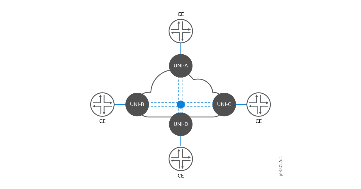
The E-Tree service model ensures clear hierarchical communication, suitable for scenarios requiring a single point of control with isolated downstream branches. In Figure 8 , a single root EVC supports multiple leaf EVCs. Service frames are exchanged between the root EVC and any leaf EVCs. Service frames cannot be exchanged between any Leaf-to-Leaf UNI EVCs. The behavior is consistent for all traffic types (Unicast, Multicast, and Broadcast).
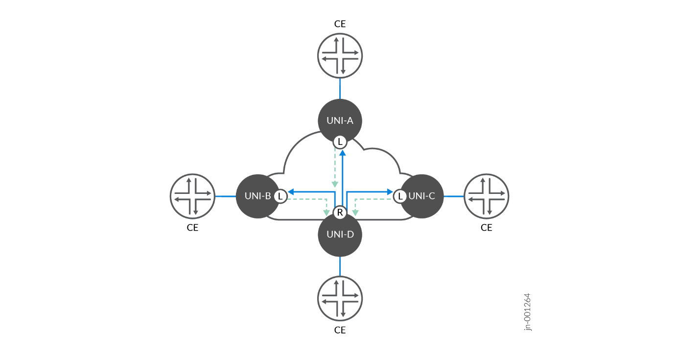
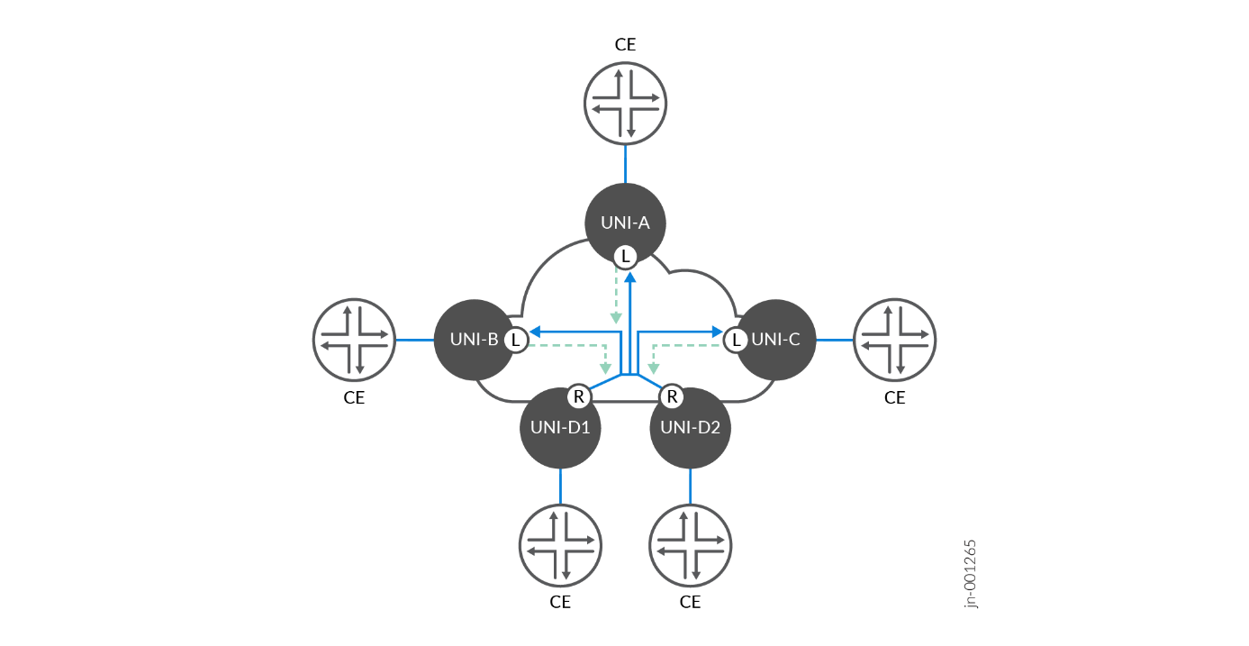
Figure 9 illustrates the second topology with multiple root EVCs. In this scenario, leaf-to-leaf communication is still forbidden to only leaf-to-root or leaf-to-multiple roots. However, root-to-root communication is allowed, providing additional reliability and high availability. The Metro EBS JVD includes dual root nodes in active-active high availability modes.
E-Tree implements similar performance categories to E-Line and E-LAN services to meet the established SLOs to ensure key performance metrics are delivered. This includes:
- Differing bandwidth rates between UNIs
- Multiple Class of Service (CoS) profiles for tailoring service levels
- Performance objectives measuring Frame Delay (FD), Inter-Frame Delay Variation (IFDV), and Frame Loss Ratio (FLR) to establish availability metrics
- Service multiplexing at one or more UNIs, enabling flexibility for rooted-multipoint services that may coexist with other service types.
These metrics ensure that the network meets specific performance levels, making it suitable for more critical applications that require reliable data transmission, such as voice, video, or financial transactions.
E-Tree services has two main variations determined by the degree of control delegated between the service provider and customer end user:
- Ethernet Private Tree (EP-Tree) is a port-based, rooted-multipoint “all-to-one bundling” service providing a dedicated and private transparent data path. All traffic on the physical port (UNI) is mapped to a single EVC. EP-Tree allows subscribers full control over their network infrastructure with the flexibility to create and manage site-to-site connectivity options. Subscriber CE-VLAN IDs and CE-VLAN CoS markings are preserved end-to-end without restrictions.
- Ethernet Virtual Private Tree (EVP-Tree) supports service multiplexing and shared bandwidth across the network. EVP-Tree enables multiple EVCs on one or more UNIs, providing greater flexibility for delivering multiple rooted-multipoint services. In parallel, point-to-point EVPL E-Line or multipoint-to-multipoint EVP-LAN EVCs may be created over a single UNI. Subscribers and/or traffic flows can be mapped to specific VLANs with flexible VLAN ID preservation and QoS mapping.
E-Tree services offer a range of possibilities for enterprises to interconnect facilities in an efficient, scalable, and secure manner. The detailed service attributes and configurations, as outlined in MEF technical specifications, provide a foundation for customizing the service to meet varying business needs.
The Iometrix MEF 3.0 validation covers the critical functionality required to deliver E-Tree services. It provides robust, flexible, and scalable solutions for organizations that require reliable rooted-multipoint Ethernet connectivity. Leveraging the Metro EBS JVD solution architecture enables the ability to scale from best-effort services to high-performance, guaranteed service delivery with strict performance objectives.
E-TREE Rooted-Multipoint Services
The protocol suite of E-Tree rooted-multipoint services covered by the JVD includes EVPN-ETREE with single or dual root nodes. The EVP-Tree use case includes 1129 MEF-related test cases executed as part of the validation. EP-Tree is supported but not included in the validation. The key service categories under the test include:
- Functional Service Attributes and Parameters
- Layer 2 Control Protocol Frame Behaviors
- Service OAM Functionalities
- Bandwidth Profile Attributes and Parameters
- Service Performance Attributes and Parameters

Multiple combinations and service attributes of EVPN-ETREE are supported beyond the scope of what is included in the JVD, with MX304 (MSE1, MSE2) as active-active root nodes and MX204 (MA4, MA5) as leaf nodes.
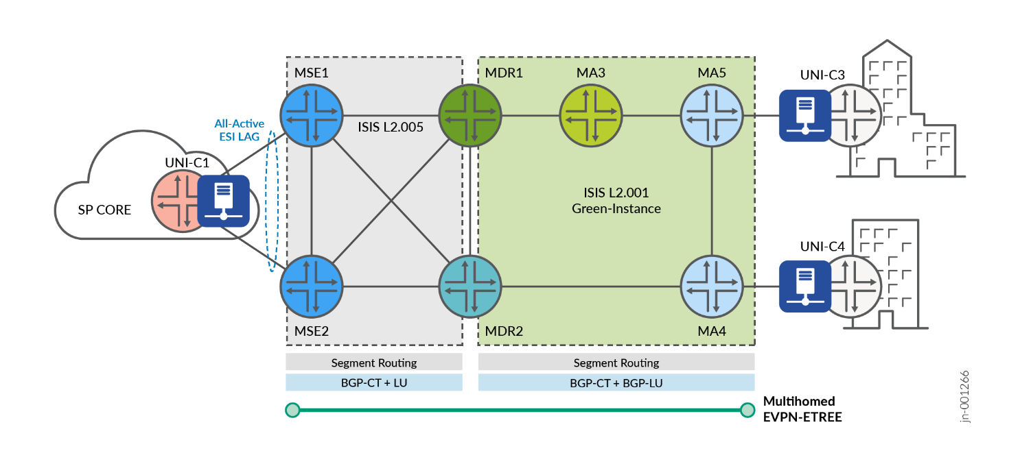
Figure 11 illustrates the lab topology with service instantiation points for E-Tree services covered by the corresponding MEF test cases. Iometrix test probes are placed throughout the topology for conducting the end-to-end validation.
| Index | Service Type | VPN Type | High Availability | Service Instantiation | Endpoints |
|---|---|---|---|---|---|
| 1 | E-Tree | EVPN-ETREE | Active-Active Roots | Metro Ring | MSE1, MSE2, MA4, MA5 |
Every VPN service included in the JVD is designed with the purpose of delivering crucial metro functionality and connectivity objectives. The services featured in Table 8 are explained below.
|
Matching Index |
EVP-TREE | Metro Use Case |
|---|---|---|
| [ 1 ] | EVPN-ETREE | EVPN-ETREE is implemented as a VLAN-based service with leaf nodes at MA4 (MX204) and MA5 (MX204). Redundant Root nodes are included at MSE1 and MSE2 (MX304) for active-active high availability. Leaf-to-leaf communication is forbidden. All-active ESI LAG is supported for UNI resiliency at the MSEs. |
For more information about the E-Tree configurations used in this JVD and in Metro Ethernet Business Services JVD, see Juniper GitHub Repository or contact your Juniper representative.
E-Tree: EVPN-ETREE Example
EVPN-ETREE is implemented as a VLAN-based service with leaf nodes at MA4 (MX204) and MA5 (MX204). Redundant Root nodes are included at MSE1 and MSE2 (MX304) for active-active high availability. Leaf-to-leaf communication is forbidden. All-active ESI LAG is supported for UNI resiliency at the MSEs. For more information, see E-TREE Rooted-Multipoint Services
The following sample configuration provides outputs for MSE1 (root), MSE2 (root), MA4 (leaf), and MA5 (leaf).
              Root: MSE1 (MX304)
interfaces {
    ae10 {
        unit 4080 {
            encapsulation vlan-bridge;
            vlan-id 4080;
            esi {
                00:10:11:11:40:80:01:62:00:01;
                all-active;
            }
            family bridge {
                filter {
                    input f_elan-evpn;
                }
            }
            etree-ac-role root;
        }
    }
}
routing-instances {
    evpn_group_80_4080 {
        instance-type evpn;
        protocols {
            evpn {
                interface ae10.4080;
                evpn-etree;
            }
        }
        vlan-id 4080;
        interface ae10.4080;
        route-distinguisher 10.0.0.10:4080;
        vrf-export evpn_group_80_4080;
        vrf-target target:63536:4080;
    }
}
Root: MSE2 (MX304)
interfaces {
    ae10 {
        unit 4080 {
            encapsulation vlan-bridge;
            vlan-id 4080;
            esi {
                00:10:11:11:40:80:01:62:00:01;
                all-active;
            }
            etree-ac-role root;
        }
    }
}
routing-instances {
    evpn_group_80_4080 {
        instance-type evpn;
        protocols {
            evpn {
                interface ae10.4080;
                evpn-etree;
            }
        }
        vlan-id 4080;
        interface ae10.4080;
        route-distinguisher 10.0.0.11:4080;
        vrf-export evpn_group_80_4080;
        vrf-target target:63536:4080;
    }
}
Leaf: MA4 (MX204)
interfaces {
    xe-0/1/5 {
        flexible-vlan-tagging;
        mtu 9102;
        encapsulation flexible-ethernet-services;
        unit 4080 {
            encapsulation vlan-bridge;
            vlan-id 4080;
            family bridge {
                filter {
                    input f_elan-evpn;
                }
            }
            etree-ac-role leaf;
        }
    }
}
routing-instances {
    evpn_group_80_4080 {
        instance-type evpn;
        protocols {
            evpn {
                interface xe-0/1/5.4080;
                evpn-etree;
            }
        }
        vlan-id 4080;
        interface xe-0/1/5.4080;
        route-distinguisher 10.0.0.16:4080;
        vrf-export evpn_group_80_4080;
        vrf-target target:63536:4080;
    }
}
Leaf: MA5 (MX204)
interfaces {
    xe-0/1/0 {
        flexible-vlan-tagging;
        mtu 9102;
        encapsulation flexible-ethernet-services;
        unit 4080 {
            encapsulation vlan-bridge;
            vlan-id 4080;
            family bridge {
                filter {
                    input f_elan-evpn;
                }
            }
            etree-ac-role leaf;
        }
    }
}
routing-instances {
    evpn_group_80_4080 {
        instance-type evpn;
        protocols {
            evpn {
                interface xe-0/1/0.4080;
                evpn-etree;
            }
        }
        vlan-id 4080;
        interface xe-0/1/0.4080;
        route-distinguisher 10.0.0.19:4080;
        vrf-export evpn_group_80_4080;
        vrf-target target:63536:4080;
    }
}
For more information about the EVPN-ETREE configurations, see Juniper GitHub Repository .
Metro as a Service: Access E-LINE
The following sections describe how MEF framework is leveraged in the JVD to deliver Metro as a Service (MaaS) solution. This section explains the Access E-Line (formerly E-Access) portion of the MEF 3.0 validation.
Access E-Line is defined by MEF 51 technical specification as a wholesale Ethernet access service based on the usage of Operator Virtual Connections (OVCs) to associate External Network-to-Network Interface (ENNI) endpoint(s) to UNI endpoint(s). The OVC enables an operator to provide Ethernet connectivity between a Customer Edge (CE) at the UNI and another service provider at the External ENNI. This model allows Ethernet services to transport across multiple operators' networks while ensuring service consistency and quality.
The UNI acts as the customer demarcation point with the service provider. The ENNI is situated at the boundary between two operator networks and serves as the connection point where the OVC terminates in the service provider’s network, transitioning to another network or service provider. When the OVC facilitates a transfer within a single operator, the connection type is called an Internal Network-to-Network Interface (INNI), but the functional characteristics are the same.
| Feature | ENNI | INNI |
|---|---|---|
| Location | Between two operator networks | Within a single operator's network |
| Purpose | Inter-operator connectivity | Intra-operator connectivity |
| Connection Type | Connects independent provider networks | Connects internal network domains |
| Example Use Case | Wholesale-to-retail provider connection | Multi-services Integration |
The Access E-Line service formed by the point-to-point OVC is called O-Line, which may interconnect a UNI to an ENNI or between two ENNIs. Multiple O-Line services may be strung together across provider domains or multi-operator networks.
Additional connectivity methods are possible to form Access E-LAN multipoint-to-multipoint (O-LAN service) but are not covered in the JVD.
Access E-Line involves the following components that differ from the previous services described so far.
- OVC-Based Architecture: The OVC links the UNI at the customer’s location to the ENNI, which interconnects different service provider networks. The OVC acts as the carrier for traffic between these interfaces, ensuring secure and reliable transport of Ethernet services across domains.
- Seamless Multi-Operator Connectivity: By leveraging OVCs, the Access E-Line service allows one operator to use another operator’s infrastructure to extend their service reachability. This facilitates end-to-end service delivery across multiple administrative domains without compromising service quality.
- OVC Types: E-Access services can support both Point-to-Point OVCs (similar to EPL services) and Multiplexed OVCs (similar to EVPL services), allowing multiple services to be delivered over a single physical connection. The service provider owning the access infrastructure may support multiple virtual circuits identified by a single VLAN ID. This flexibility makes it suitable for a wide variety of business and wholesale scenarios.
Access E-Line may be leveraged to deliver several use cases, including:
- Wholesale Access: A service provider can offer access services to other network operators, allowing them to deliver Ethernet services in regions outside their own network footprint.
- Multi-Domain Ethernet Services: Access E-Line simplifies the process of offering Ethernet services across multiple operators' networks by using standardized OVCs at the ENNI.
Access E-Line allows operators to extend service offerings while maintaining control over the quality and performance.
Access E-Line Services
The protocol suite of point-to-point OVC Access E-Line covered by the JVD includes approximately 400 MEF-related test cases in the validation of the following key service categories:
- Functional Service Attributes and Parameters
- Layer 2 Control Protocol Frame Behaviors
- Service OAM Functionalities
- Bandwidth Profile Attributes and Parameters
- Service Performance Attributes and Parameters

Multiple combinations and service attributes of Access E-Line are supported beyond the scope of what is included in the JVD, such as Access E-LAN, Access E-Tree, and Access E-Transit permutations. O-Line services are point-to-point in nature and may be chained to connect disparate UNIs across multiple O-Line connections. OVC pairs forming O-Line services may consist of the following connectivity types:
- Connecting two External or Internal NNIs (ENNI or INNI)
- Connecting OVC endpoints (ENNI or INNI) within the same device (aka Hairpinning)
- Connecting ENNI or INNI to a UNI
Two options featured in the JVD to facilitate Access E-Line include leveraging local-switched services: L2CCC with L2Circuit local-switching and EVPN-VPWS local-switching.

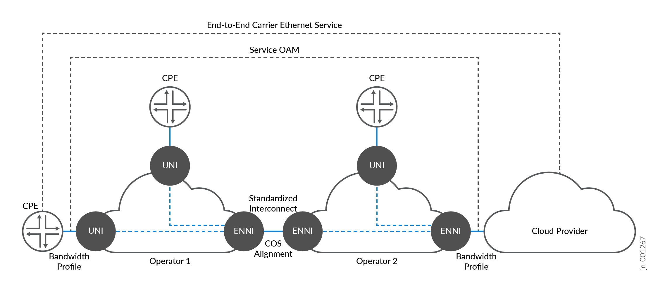
Figure 14 illustrates end-to-end connectivity achieved across multiple O-Line services for a cloud provider interconnection.
EVCs are service multiplexed, which may support multitenant use cases. At the transit point of MA5 (MX204), an S-TAG is mapped to the OVC endpoint toward MA3 (ACX7100-48L) to support INNI-to-INNI connectivity within the same Carrier Ethernet network. Traffic is exchanged across the interdomain segment using S-TAG information. C-TAGs and CoS markings are preserved. The S-TAG may be removed at the ENNI OVC to expose the original C-TAG infrastructure to the cloud provider. The interworking’s of how the O-Line services are achieved are flexible and dependent on the use case requirements. Extending or swapping S-TAG at the ENNI-to-NNI exchange may be preferred to continue transporting CE-VLANs transparently.
For more information about the Access E-Line configurations used in this JVD and in Metro Ethernet Business Services JVD, see Juniper GitHub Repository or contact your Juniper representative.
Access E-Line: EVPN-VPWS Local-Switching Example
Access E-Line (formerly E-Access) services are delivered with several permutations. The JVD includes common local-switching methodologies using EVPN-VPWS or L2Circuit (L2CCC). A range of VLAN-IDs are identified at the OVC ENNI position, pushing an outer S-TAG. The transport network to the destination OVC needs only to be aware of the outer VLAN-ID. For more information, see Metro as a Service: Access E-LINE section.
The following sample configuration provides outputs for MA3 (ACX7100-48L).
              MA3 (ACX7100-48L)
interfaces {
    et-0/0/0 {
        flexible-vlan-tagging;
        mtu 9102;
        encapsulation flexible-ethernet-services;
        ether-options {
            ethernet-switch-profile {
                tag-protocol-id [ 0x8100 0x88a8 ];
            }
        }
        unit 2500 {
            encapsulation vlan-ccc;
            vlan-id-list 2500-2599;
            input-vlan-map {
                push;
                tag-protocol-id 0x88a8;
                vlan-id 4082;
            }
            output-vlan-map pop;
            family ccc {
                filter {
                    input f_eline-evpn-vpws;
                }
            }
        }
    }
    et-0/0/51 {
        mtu 9102;
        ether-options {
            ethernet-switch-profile {
                tag-protocol-id [ 0x8100 0x88a8 ];
            }
        }
        unit 4082 {
            encapsulation vlan-ccc;
            vlan-tags outer 0x88a8.4082;
        }
    }
}
routing-instances {
    lsw_evpn_vpws_group_90_4082 {
        instance-type evpn-vpws;
        protocols {
            evpn {
                interface et-0/0/0.2500 {
                    vpws-service-id {
                        local 22;
                        remote 11;
                    }
                }
                interface et-0/0/51.4082 {
                    vpws-service-id {
                        local 11;
                        remote 22;
                    }
                }
                control-word;
            }
        }
        interface et-0/0/0.2500;
        interface et-0/0/51.4082;
        route-distinguisher 10.0.0.15:4082;
        vrf-target target:63533:4082;
    }
}
For more information about Access E-Line configurations, see Juniper GitHub Repository .
Access E-Line: L2Circuit Local-Switching Example
A similar configuration, leveraging L2Circuit local-switching, is accomplished with the following sample configuration.
              MA3 (ACX7100-48L)
interfaces {
    et-0/0/0 {
        flexible-vlan-tagging;
        mtu 9102;
        encapsulation flexible-ethernet-services;
        ether-options {
            ethernet-switch-profile {
                tag-protocol-id [ 0x8100 0x88a8 ];
            }
        }
        unit 2500 {
            encapsulation vlan-ccc;
            vlan-id-list 2500-2599;
            input-vlan-map {
                push;
                tag-protocol-id 0x88a8;
                vlan-id 4082;
            }
            output-vlan-map pop;
            family ccc {
                filter {
                    input f_eline-evpn-vpws;
                }
            }
        }
    }
    et-0/0/51 {
        mtu 9102;
        ether-options {
            ethernet-switch-profile {
                tag-protocol-id [ 0x8100 0x88a8 ];
            }
        }
        unit 4082 {
            encapsulation vlan-ccc;
            vlan-tags outer 0x88a8.4082;
        }
    }
}
protocols {
    l2circuit {
        local-switching {
            interface et-0/0/0.2500 {
                end-interface {
                    interface et-0/0/51.4082;
                }
                ignore-mtu-mismatch;
            }
        }
    }
}