Install the Mounting Hardware for a QFX5700 Switch
You can install a QFX5700 switch into a four-post rack by using a mechanical lift, or you can install it manually.
Before you install the switch:
-
Prepare the site for installation.
-
Be sure the site has adequate clearance for both airflow and hardware maintenance.
-
Unpack the switch
-
Review the chassis lifting guidelines.
Do not install line cards in the chassis until after you mount the chassis securely on a rack or cabinet
Before mounting the switch on a rack or cabinet, have a qualified technician verify that the rack or cabinet is strong enough to support the weight of the switch and is adequately supported at the installation site.
If you are installing more than one switch in a rack or cabinet, install the first switch at the bottom of the rack.
Manually Mount a QFX5700 Switch on a Four-Post Rack
To manually mount a QFX5700 switch in a Four-Post Rack:
The switch weighs approximately 250 lb (113 kg). Lifting the chassis and mounting it in a rack or cabinet requires at least three people. Make sure the chassis is empty (contains only the midplane) before you lift it.
Before you install the switch remove the FRUs if pre-installed:
-
Remove a QFX5700 Routing and Control Board
-
Remove a QFX5700 Forwarding Engine Boards
-
Remove a QFX5700 FPCs
-
Remove a QFX5700 Fan Tray
-
Remove a AC/HVDC Power Supply or remove a DC Power Supply:
Be sure that you have the following parts and tools available to install the switch:
-
Eighteen mounting screws appropriate for your rack (not provided)
-
A Phillips (+) screwdriver, number 1, 2, or 3, depending on the size of your rack-mounting screws
To manually install the switch in the rack or cabinet:
-
Wrap and fasten one end of the ESD wrist strap around your bare wrist, and connect the other end of the strap to the ESD point on the device.
-
Using a Phillips screwdriver, remove the screw on each side of the chassis that holds the rear mounting-blades to the chassis.
Slide the mounting blades out of the channels.
Figure 1: Removing the Rear-Mounting Blades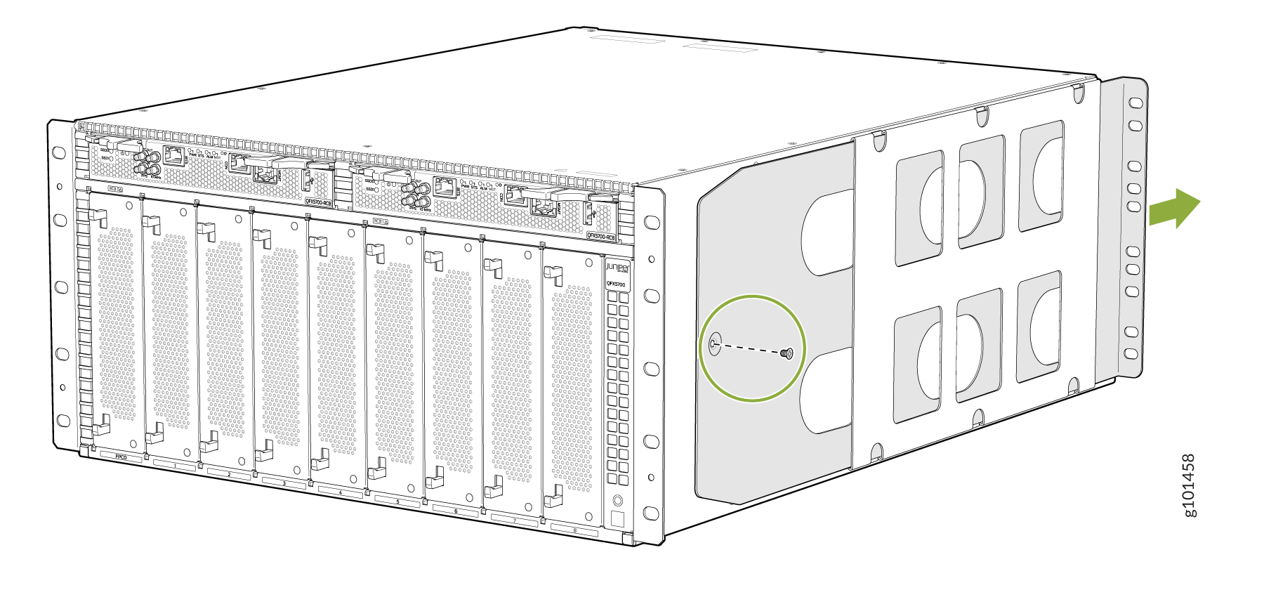
With one person on each side, hold on to the bottom of the chassis, and carefully lift the chassis and position it in the rack so that the front brackets are aligned with the rack holes.
Figure 2: Lift the Chassis by Hand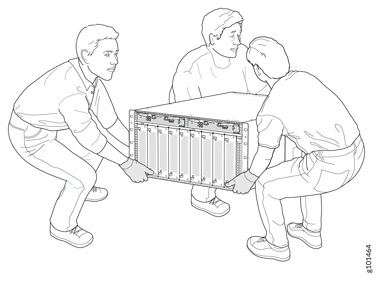 Figure 3: QFX5700 Switch Installed in a Four-Post Rack
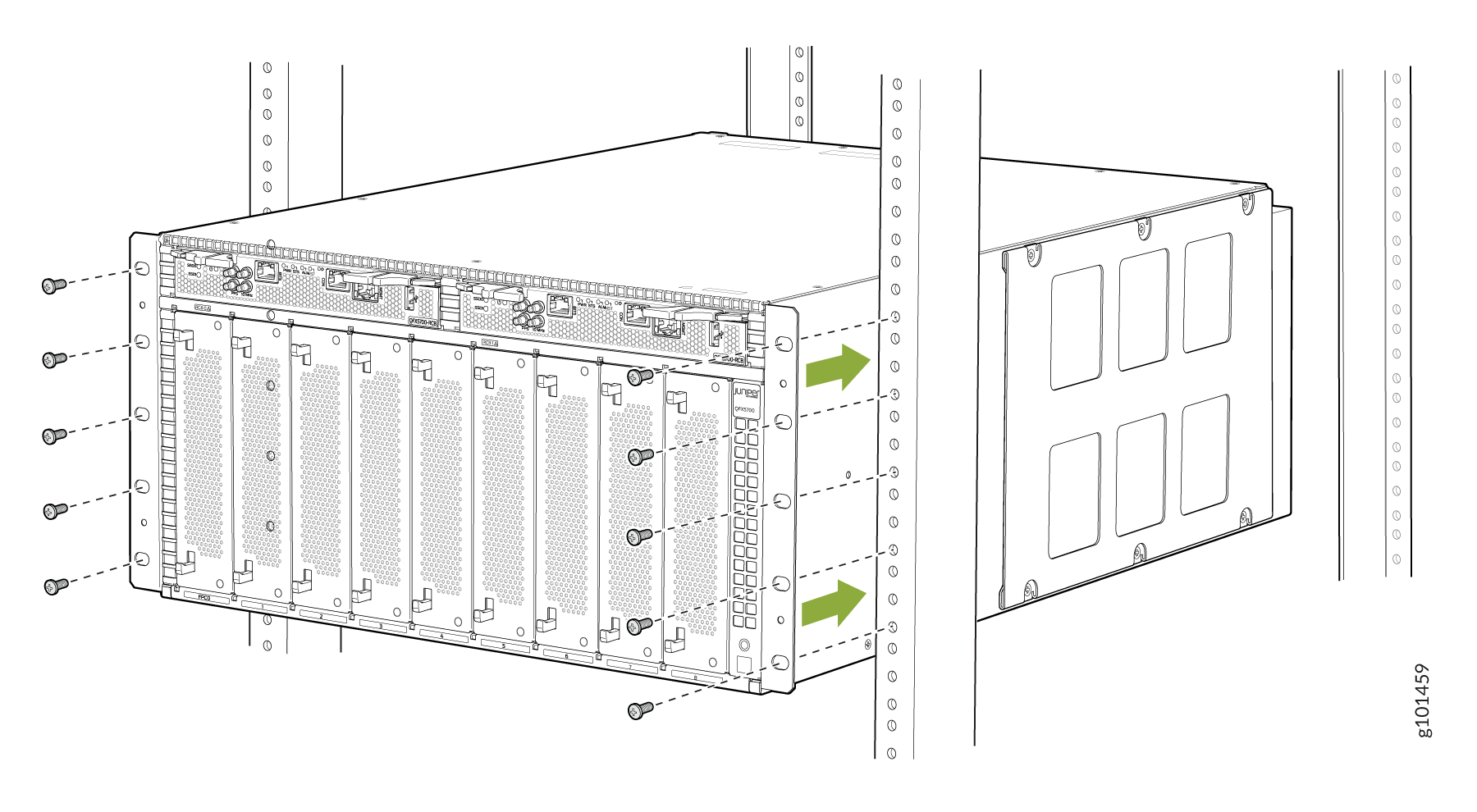
-
With two people continuing to support the chassis the third person can install mounting screws into each of the front-mounting bracket holes aligned with the rack, starting from the bottom, and tighten the screws.
On the rear of the chassis, slide the rear-mounting blades into the channels on either side of the chassis until the rear-mounting brackets at the end of the blades contact the rack rails

-
Install mounting screws into each of the rear-mounting bracket holes aligned with the rack, starting from the bottom, and secure them tightly.
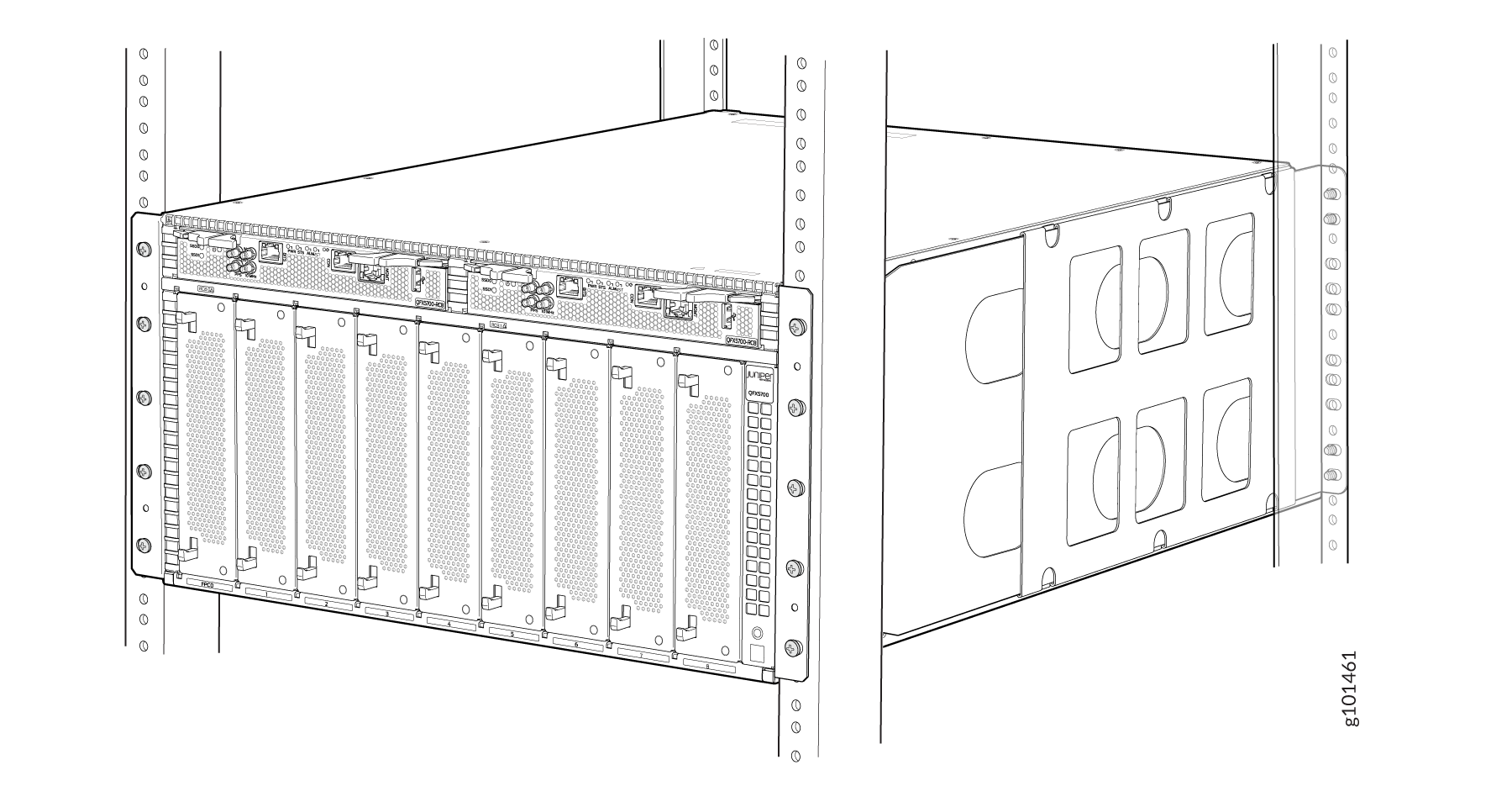
Visually inspect the alignment of the chassis. If you’ve installed the chassis properly in the rack, all the mounting screws on one side of the rack are aligned with the mounting screws on the opposite side, and the switch is level.
-
If you have removed any pre-installed FRUs, reinstall them:
-
Install a QFX5700 Routing and Control Board
-
Install a QFX5700 Forwarding Engine Board
-
Install a QFX5700 FPCs
-
Install a QFX5700 Fan Tray
-
Install a AC/HVDC Power Supply/DC Power Supply
-
-
Installing a QFX5700 Switch using a Mechanical Lift
These steps list the procedure involved to mount a QFX5700 switch in a Four-Post Rack Using a Mechanical Lift
Be sure that you have the following parts and tools available to install the switch:
-
A mechanical lift rated for 250 lb (113.4 kg)
-
Eighteen mounting screws appropriate for your rack (not provided)
-
A Phillips (+) screwdriver, number 1, 2, or 3, depending on the size of your rack-mounting screws
Because of the size and weight of the switch, we strongly recommend that you use a mechanical lift to install the QFX5700.
To install the switch using a mechanical lift:
-
Slide the mounting blades out of the channels.
Figure 4: Removing the Rear-Mounting Blades
-
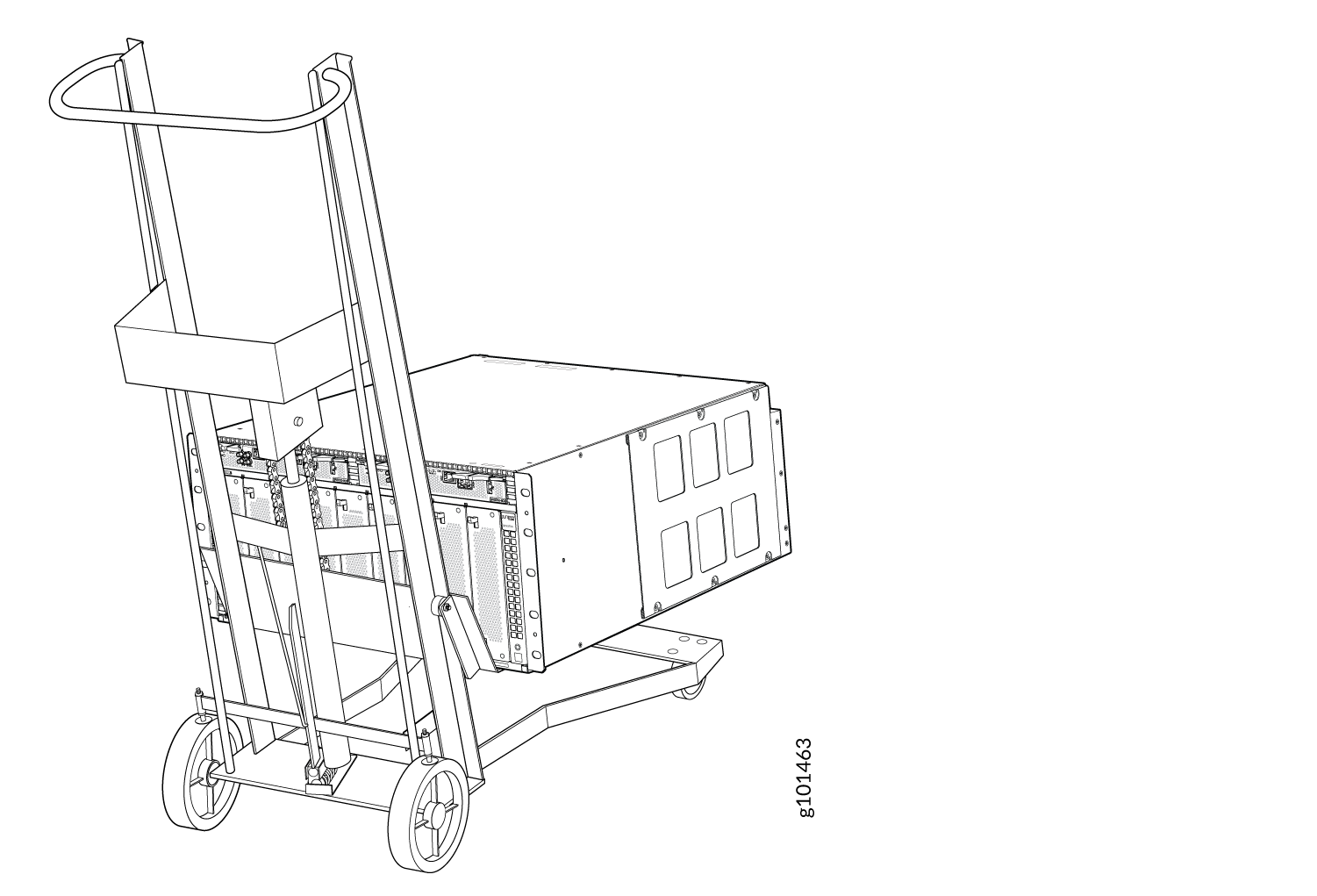
Load the switch onto the lift, making sure it rests securely on the lift
platform.
Figure 5: Load the QFX5700 Switch onto a Mechanical Lift
-
Carefully position the chassis in the rack until the holes of the
front-mounting brackets align with the holes in the rack rails.
Figure 6: Install the QFX5700 Router in a Four-Post Rack
-
On the rear of the chassis, slide the rear-mounting blades into the
channels on either side of the chassis until the rear-mounting brackets at
the end of the blades contact the rack rails.
-
Visually inspect the alignment of the chassis. If you’ve installed the
chassis properly in the rack, all the mounting screws on one side of the
rack are aligned with the mounting screws on the opposite side, and the
switch is level.
Figure 7: Fully installed chassis